patent · US6278197
Contra-rotating wind turbine system
21 August 2001
Page 1 — bibliographic record
(12) United States Patent (10) Patent No.: US 6,278,197 B1 Appa (45) Date of Patent: Aug. 21, 2001
(54) CONTRA-ROTATING WIND TURBINE (74) Attorney, Agent, or Firm-Albert W. Hilburger
SYSTEM
(76) Inventor: Kari Appa, 22242 Anthony Dr., Lake Wind turbine apparatus includes an upright mast with Sup Forest, CA (US) 92630-2327 port bearings underlying and rotatably Supporting a hub (*) Notice: Subject to any disclaimer, the term of this assembly having inner and outer coaxial shafts telescopi patent is extended or adjusted under 35 cally related but radially Spaced to permit independent U.S.C. 154(b) by 0 days. rotation about a generally horizontal axis. An armature winding is provided on the Outer Shaft and a plurality of (21) Appl. No.: 09/498,769 dielectrically Separated magnets are mounted on the inner shaft at a plurality of circumferentially spaced locations. A (22) Filed Feb. 5, 2000 first set of rotor blades is mounted on the inner shaft at a (51) Int. C.7 F03D 9/00; H02D 9/04 plurality of circumferentially spaced locations, the rotor (52) U.S. Cl. ................................................. 290/55; 290/54 blades extending radially away from the axis of rotation and (58) Field of Search .................................. 290/43, 44, 54, positioned on the inner Shaft for rotating the inner shaft in a 290/55 first direction about the axis of rotation when subjected to wind-induced air flow. A second set of rotor blades is (56) References Cited Similarly mounted on the outer Shaft axially Spaced from the
first set of rotor blades for rotating the outer shaft about the axis of rotation in an opposite direction. The hub assembly 4,061,926 12/1977 Peed ....................................... 290/55 may be selectively positioned in azimuth So that the first Set 4,648,801 3/1987 Wilson ................................. 416/171 of rotor blades is relatively closer to the wind-induced air 4,976,587 12/1990 Johnston et al. ..................... 416/230 flow, or windward, and the second set of rotor blades is 5,419,683 5/1995 Peace ................ 416/227A relatively farther from the wind-induced air flow, or leeward. 5,456,579 10/1995 Olson ..................................... 416/23 Electrical power is generated as the armature winding on the 5,506,453 4/1996 McCombs .............................. 290/44 6,127,739 10/2000 Appa ...................................... 290/55 outer Shaft and the plurality of magnets on the inner Shaft 6,172,429 1/2001 Russell ................................... 290/54 rotate in opposite directions and power transfer apparatus is 6.215,199 * 3/2001 Lysenko et al. ....................... 290/44 provided for drawing off the electrical power from the hub assembly to a distant receiver.
* cited by examiner
Primary Examiner Nicholas Ponomarenko 17 Claims, 5 Drawing Sheets
ASNS Say Sy N.Nh A
Ye Saw Yasayanae
Page 2
Drawing sheet — no readable text.
Page 3
Drawing sheet — no readable text.
Page 4
Drawing sheet — no readable text.
Page 5
Drawing sheet — no readable text.
Page 6
Drawing sheet — no readable text.
Page 7
CONTRA-ROTATING WIND TURBINE with high tip speed of large diameter rotor. Then too, Single SYSTEM rotor renewable energy devices are limited in their use Since a high torque is necessary to Self start the System and
BACKGROUND OF THE INVENTION therefore can be installed only in regions with consistently 1. Field of the Invention high wind Speeds.
The present invention relates generally to a wind energy A Small number of patents are typical of the known prior conversion System and, more particularly, to the design and art attempting to improve on earlier efforts to harneSS wind manufacture of a jet assisted contra-rotating wind turbine energy. For example, U.S. Pat. No. 5,456,579 to Olson System. discloses a wind turbine blade with a governor to maintain 2. Prior Art optimum rotational Speed. The governor positions an aileron for varying wind Speed and includes a lead weight posi
In recent years, it has become apparent that conventional tioned at the wing tip and connected to a mechanism that methods of generating electricity will Soon be insufficient to deploys the aileron to achieve the maximum lift to drag ratio meet the World's ever-growing need for electric power. at all wind speeds. U.S. Pat. No. 5,419,683 to Peace dis Several factors, including the pollution which results from 15 closes a method of installing a plurality of wind turbines on the combustion of fossil fuels, the dangers associated with chimneys, towerS or the like. Two rotors having their hori the operation of nuclear reactors, and the limitations inherent Zontal axes are mounted back to back on a ring that turns in the traditional hydroelectric as well as the more modern about the chimney. The primary concept of this invention is Solar energy approaches to the generation of electricity, have to utilize existing Structures to mount a plurality of wind encouraged the development of alternative Sources of elec turbines and to eliminate the need for wind farms. U.S. Pat. tric power, Such as the wind turbine generator. No. 4,976,587 to Johnston et al. discloses a method for In recent years, wind energy projects have included the manufacturing composite blades having highly improved installation of large numbers of wind turbine generating aerodynamic efficiency. The blades employ the NASA air Systems at locations having favorable wind conditions. foil section LS(1)-04XX having 29 per cent thickness at 3/10 Several of these so-called “wind farms” have been located in 25 radius and 18 per cent at the blade tip. The airfoil section the state of California. However, during the 1980s, it became comprises two spars which terminate into a circular Section apparent that the various wind energy projects using wind at the hub. U.S. Pat. No. 4,648,801 to Wilson discloses a turbines to generate electrical energy Suffered from a major method of compressing air by means of a wind turbine. The problem in that the turbines were not receiving the amount air is drawn from the low energy region of the downwind of wind energy that was projected based on the initial wind Stream. The compressed air is connected to the intake of a Studies that were conducted. Many reasons have been prime mover (Such as a diesel engine, a gasoline engine, or advanced for this shortfall of wind energy. Little can be done a gas turbine) to boost its output power and drives an about the wind itself, with the exception of understanding alternator.
the available resource better by using direct measurement It was with knowledge of the foregoing State of the and analysis. However, a new rotor blade System according 35 technology that the present invention has been conceived to the present invention, designed to take better advantage of and is now reduced to practice.
the available wind resource, provides an opportunity for a
Significant energy increase. SUMMARY OF THE INVENTION AS noted, then, wind turbines are renewable energy The present invention relates to wind turbine apparatus devices that are currently useful but not able to optimally 40 which includes an upright mast with Support bearings under extract energy from the wind. According to Albert Betz, a lying and rotatably Supporting a hub assembly having inner German engineer, pioneer in optimizing wind energy and Outer coaxial shafts telescopically related but radially utilization, and author in 1926 of “Wind Energie und Aus Spaced to permit independent rotation about a generally nutZung durch Windmuehlen', an ideal rotor disk can horizontal axis. An armature winding is provided on the deliver to a selected task 59% of the total wind energy 45 outer Shaft and a plurality of dielectrically Separated mag generated. For example, an ideal rotor disk is expected to nets are mounted on the inner Shaft at a plurality of circum yield 797 watts per square meter at 13 m/sec of wind speed. ferentially Spaced locations. A first Set of rotor blades is In contrast, a practical wind turbine, according to Paul Gipe, mounted on the inner shaft at a plurality of circumferentially a more recent well known promoter of wind energy tech Spaced locations, the rotor blades extending radially away nology in the United States, author of many books on the 50 from the axis of rotation and positioned on the inner Shaft for subject, his most recent contribution being “Wind Energy rotating the inner Shaft in a first direction about the axis of Comes of Age”, John Wiley & Sons, Inc., New York, 1995, rotation when Subjected to wind-induced air flow. A Second can only deliver less than 20% of the available power which set of rotor blades is similarly mounted on the outer shaft is about 100 to 250 watts/mi. Even the most acclaimed axially Spaced from the first Set of rotor blades for rotating Bergey’s BWC EXCEL wind turbine yields only 260 watts/ 55 the outer Shaft about the axis of rotation in an opposite m’. Michael Bergey is a small wind turbine manufacturer in direction. The hub assembly may be selectively positioned the United States whose BWC EXCEL model is generally in azimuth so that the first set of rotor blades is relatively considered to be the most efficient wind turbine machine in closer to the wind-induced air flow, or windward, and the the United States. The reason for such a significantly low second set of rotor blades is relatively farther from the energy conversion efficiency may be attributed to the down 60 wind-induced air flow, or leeward. Electrical power is gen Stream Velocity (V) being greater than one half of the erated as the armature winding on the outer Shaft and the upstream Velocity (V). Thus, a wind turbine comprising of plurality of magnets on the inner Shaft rotate in opposite a single rotor System cannot possibly extract the amount of directions and power transfer apparatus is provided for power Suggested by Betz. Consequently, more than 60% of drawing off the electrical power from the hub assembly to a the usable energy is Swept away in the downstream wind. 65 distant receiver.
Another drawback of a single rotor System is that it expe To circumvent the deficiencies of a single rotor turbine, a riences a large power loSS resulting from drag associated jet assisted, contra-rotating wind turbine System is proposed
Page 8
to extract almost twice the amount of wind power at half the Still another feature of the present invention is the pro cost of known devices. The proposed wind turbine System Vision of Such a wind energy conversion System which involves three distinct innovations. In a first instance, the employs two rotors turning in opposite directions, the rotors turbine design of the invention comprises a pair of rotors being mounted coaxially and assuming the dual role of a directly mounted on a pair of co-axial shafts having airfoil torque transmitting device as well as an alternator. This shaped bearing Supports. The turbine rotors are Set to rotate concept increases the relative magnetic flux rate at lower in opposite directions. The co-axial shafts play the dual role rotor Speed and almost doubles the energy conversion effi of an alternator as well as a torque-transmitting device. The ciency compared to a large diameter Single rotor System. outer surface of the inner shaft is imbedded with permanent Yet another feature of the present invention is the provi magnets, while the inner Surface of the outer Shaft is wound Sion of Such a System which recovers the thermal energy with armature coils. Thus, the dual-use direct drive concept generated as iron and copper losses and also the kinetic reduces the weight and cost of the turbine unit. More energy of air that Surrounds the hub region. Certain amount importantly, a twin rotor System extracts a Substantially of air is drawn through an inlet to cool the alternator. The hot increased amount of power from the wind. It also provides air finally passes through the leeward rotor blades and exits increased relative Speed in the magnetic field that improves 15 at the blade tips as countervailing jets imparting additional electrical performance and results in alternators of reduced torque.
weight and reduced cost. Still a further feature of the present invention is the In a Second instance, disk theory assumes uniform flow provision of Such a System which improves the aerodynamic through the rotor, while blade theory Suggests that the tip efficiency of rotor blades by removing the air blockage Section of the rotor blade is more effective than the root-For behind the leeward rotor and re-directing it through radial the benefit of the reader, Albert Betz used change of momen passages extending the length of each of the leeward rotor tum of wind energy acroSS the Spinning rotor to compute blades and exiting tangentially at the blade tips to assist the thrust on the rotor blades, an approach known as “disk rotor in developing additional torque.
theory”. “Blade theory' uses wind tunnel measured lift, drag Other and further features, advantages, and benefits of the and pitching moment coefficients along the Span of the blade invention will become apparent in the following description to compute thrust and torque on the rotor blades. In other 25 taken in conjunction with the following drawings. It is to be words, the kinetic energy of the air mass that Surrounds the understood that the foregoing general description and the hub is simply Swept away in the downstream flow of air. following detailed description are exemplary and explana This may be the main reason why practical wind turbines tory but are not to be restrictive of the invention. The could not achieve the power density projected by the disk accompanying drawings which are incorporated in and theory. In addition, at full load conditions, an alternator constitute a part of this invention, illustrate one of the generates heat due to iron and copper losses (IR). For a embodiments of the invention, and together with the typical alternator, this loss amounts to about 10 to 15% of description, Serve to explain the principles of the invention the input power. Therefore, the present invention proposes in general terms. Like numerals refer to like parts throughout the construction of a wind turbine which converts the kinetic the disclosure.
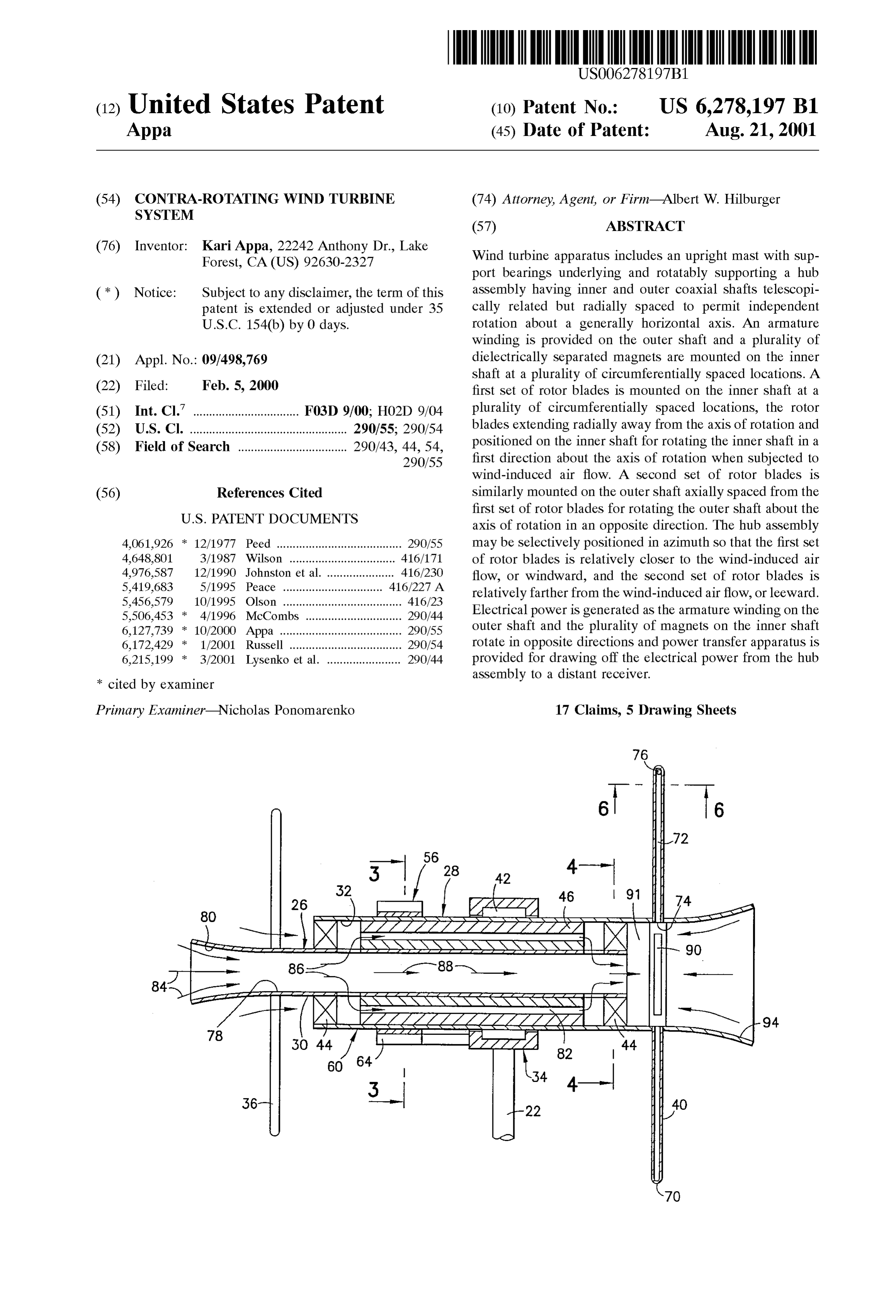
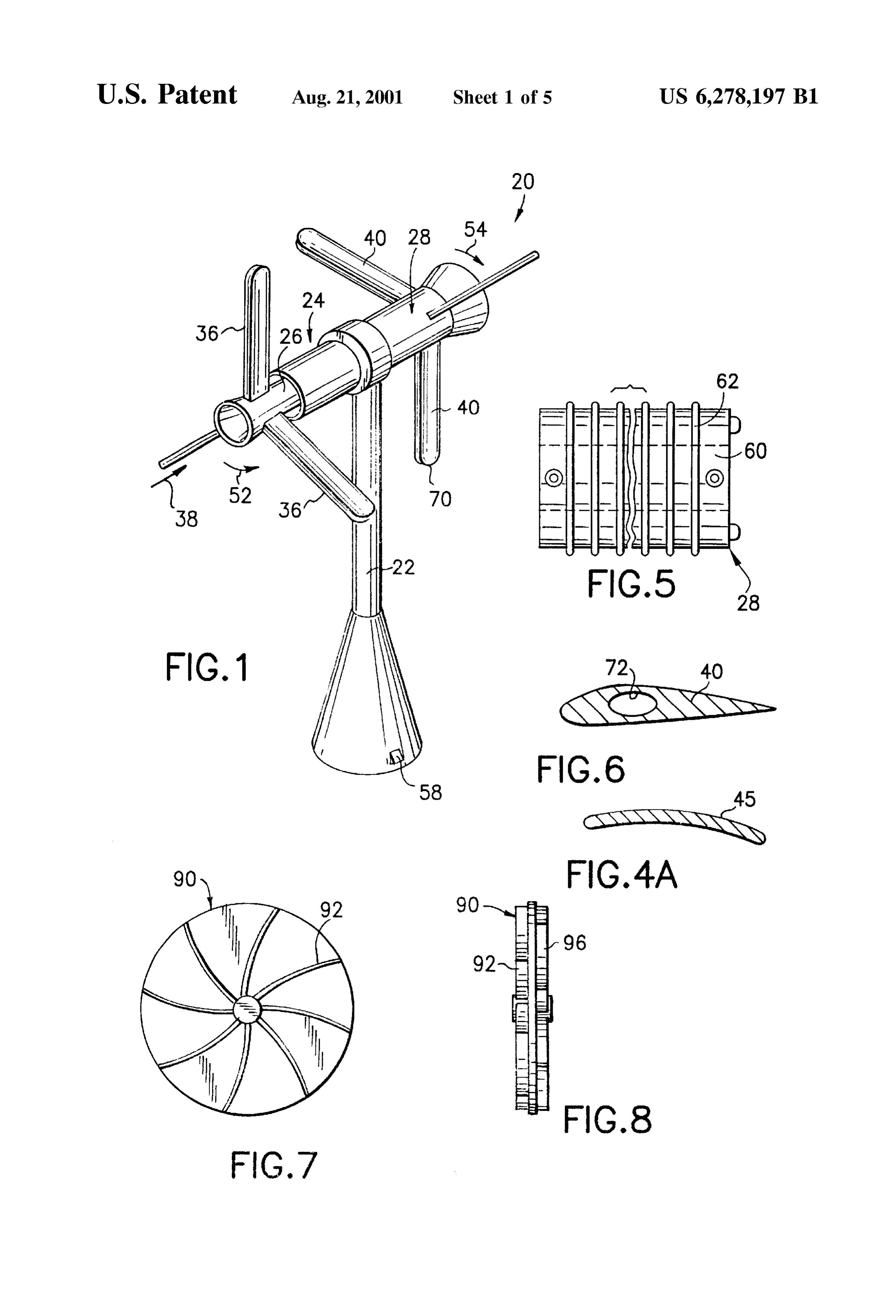
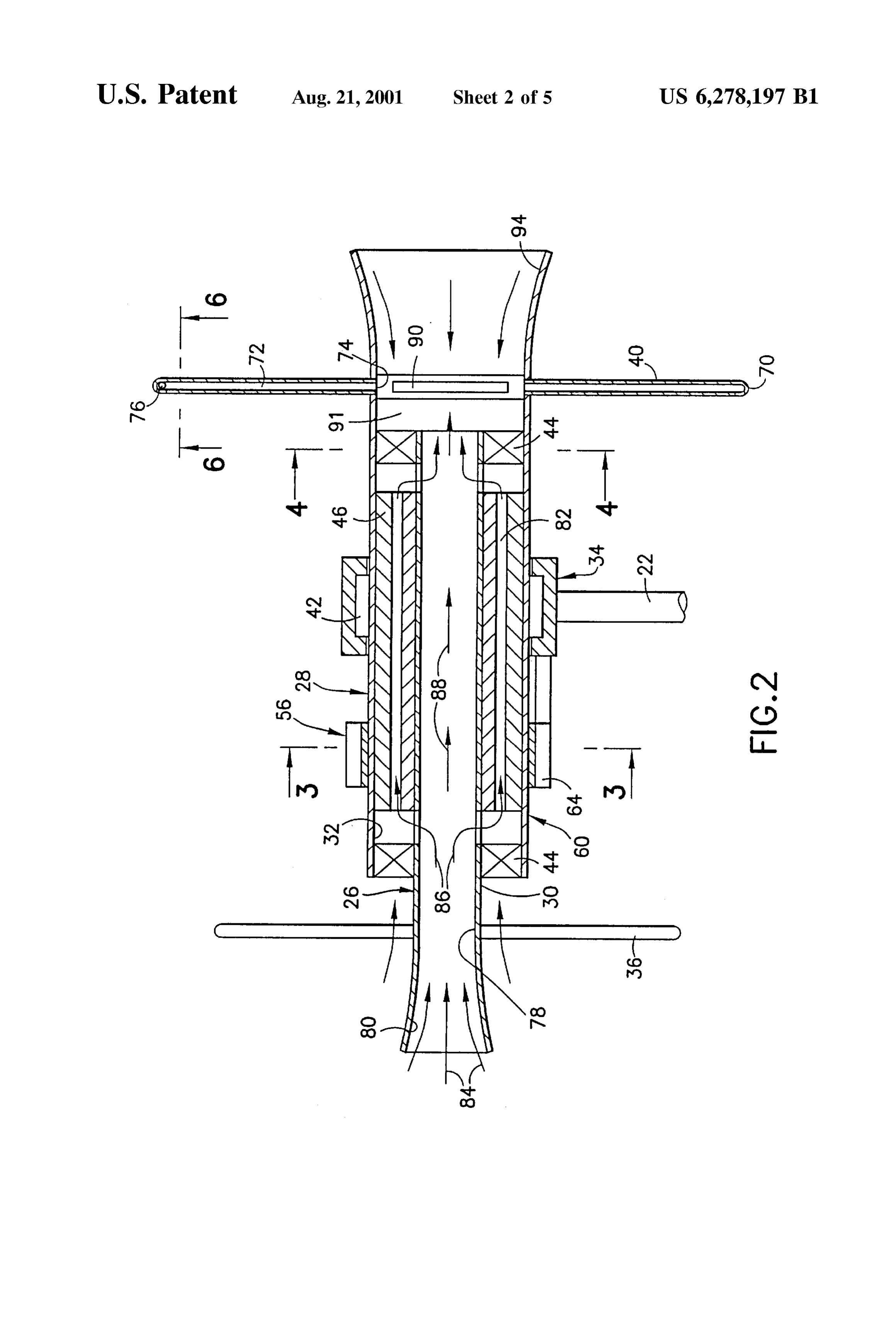
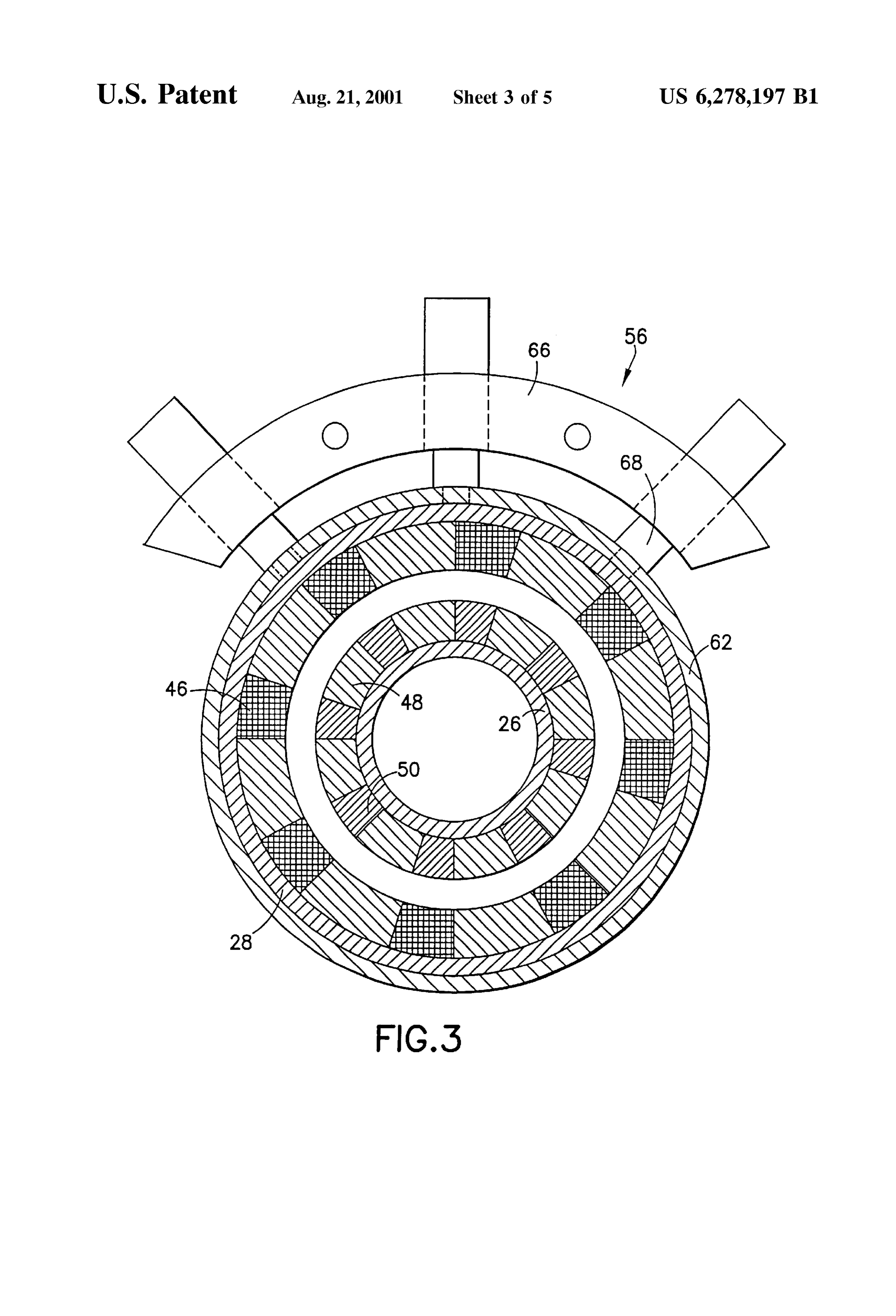
energy of wind-driven air flow and the thermal energy of the 35 BRIEF DESCRIPTION OF THE DRAWINGS alternator into electrical energy. AS wind-driven air flows through a hub assembly past a set of windward turbine The foregoing aspects and other features of the present blades toward a set of leeward turbine blades, the air passes invention are explained in the following description, taken through an air gap Surrounding the alternator. While passing in connection with the accompanying drawings, wherein: through the air gap Surrounding the alternator, heat is FIG. 1 is a perspective view of a wind turbine system extracted from the alternator and cools the armature. Finally, 40 embodying the present invention; the hot air is directed through a radial passage extending the FIG. 2 is a longitudinal cross section view of a hub length of each of the leeward rotor blades and exits tangen assembly depicting in greater detail the operational compo tially at the blade tips to assist the rotor in developing nents of the wind turbine system of the invention; additional torque. Thus, the kinetic energy of the air mass that surrounds the hub and the thermal energy of the 45 FIG. 3 is a croSS Section view taken generally along line alternator are transformed into electrical energy. 3–3 in FIG. 2;
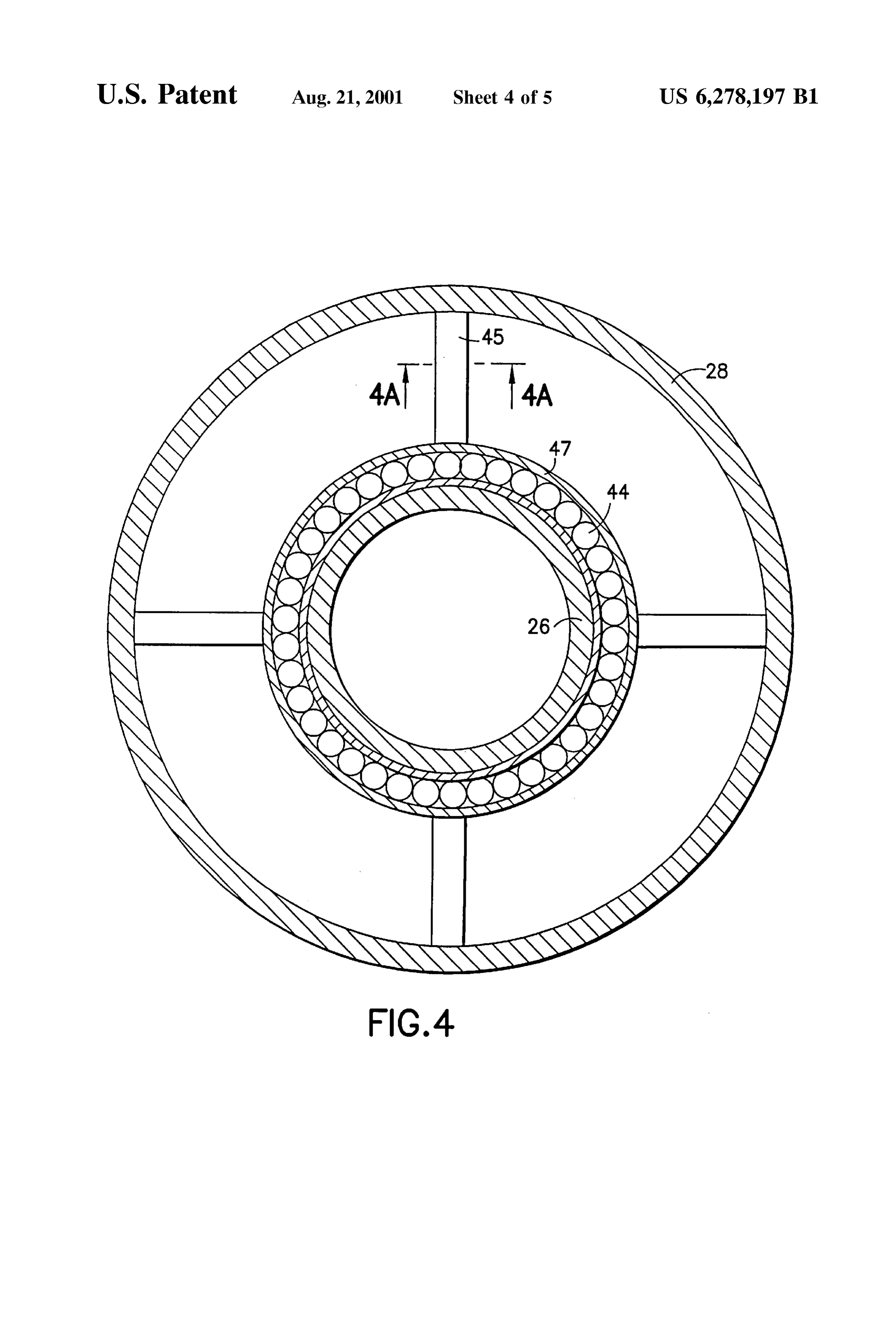
As discussed above, the two-rotor wind turbine system of FIG. 4 is a croSS Section view taken generally along line the invention extracts more energy from the wind than a 4-4 in FIG. 2;
Single rotor System. Consequently, a low energy region is FIG. 4A is a croSS Section view taken generally along line created behind the second rotor. This is called the wake and 50 4A-4A in FIG. 2;
causes air blockage. This air blockage impairs the aerody FIG. 5 is a detail side elevation view of components namic performance of the rotor blades. To avoid this within the hub assembly of the invention;
Situation, a turbofan having double-sided impeller is FIG. 6 is a croSS Section view taken generally along line employed. This turbofan is driven by the generated armature 6–6 in FIG. 2;
current and pumps a certain mass of air that passes through 55 FIG. 7 is a detail end elevation view of a fan employed by the leeward rotor blades and exits as countervailing jets at the invention;
the tip of each blade. Although, a certain amount of energy FIG. 8 is a side elevation view of the fan illustrated in is used to pump the air through the rotor blades, the removal FIG. 7;
of air blockage enhances the aerodynamic performance of FIG. 9 is a diagrammatic representation of Betz's disk the blades. Indeed, the exceSS energy produced by means of 60 analogy, and improved performance outweighs the energy consumed by FIG. 10 is an energy balance diagram representative of the the turbofan.
operation of the invention.
A primary feature, then, of the present invention is the provision of an improved wind energy conversion System. DETAILED DESCRIPTION OF THE Another feature of the present invention is the provision 65 PREFERRED EMBODIMENT of Such a wind energy conversion System which employs jet Referring to FIG. 1, there is shown a perspective view of assisted contra-rotating rotor blades. a wind turbine System 20 incorporating features of the
Page 9
S 6 present invention. Although the present invention will be outer peripheral Surface. Viewing especially FIG. 3, the described with reference to the single embodiment shown in power transfer apparatuS 56 includes a plurality of brush the drawings, it should be understood that the present holderS 66 and a Support 64 mounted on the bearing assem invention can be embodied in many alternate forms of bly 34. In turn, a plurality of annular brush holders 66 are embodiments. In addition, any Suitable size, shape or type of mounted on the brush holder support 64 and a plurality of elements or materials could be used. sets of brushes 68 supported on the brush holder slidably In FIG. 1, the wind turbine system 20 is seen to include engage with the Slip ringS 62, each Set of the brushes being an upright mast 22 Supporting a hub assembly 24 including engaged with an associated one of the Slip rings. inner and outer coaxial shafts 26, 28, respectively. AS better Each of the leeward rotor blades 40 extends radially away seen in FIG. 2, the inner shaft 26 has an outer peripheral from the outer shaft 28 to a tip end 70 and has a radial surface 30 and the outer shaft 28 has an inner peripheral passage 72 (FIGS. 2 and 6) extending from an inlet 74 at the surface 32 spaced from the surface 30. A Support bearing 34 inner peripheral surface 32 of the outer shaft 28 to a on the upright mast 22 underlies the hub assembly 24 and tangentially directed outlet 76 at the tip end. Preferably, the rotatably supports the hub assembly. With this construction, diameter of the leeward rotor blades 40 is greater than the the hub assembly 24 may be selectively positioned in 15 diameter of the windward rotor blades 36 so that the leeward azimuth so that a first set of rotor blades 36 are relatively rotor extracts extra energy from the undisturbed free Stream closer to wind-induced air flow, represented by an arrow 38, at no additional cost. Furthermore, the inner shaft 26 is or windward, and a second set of rotor blades 40 are hollow, defining an axially extending duct 78 with a wind relatively farther from the wind-induced air flow, or leeward. ward inlet nozzle 80 for receiving the wind-induced air. The A Suitable first bearing 42, Sustained on the Support spacing between the inner shaft 26 and the outer shaft 28 bearing 34 at the upper regions of the upright mast 22, defines an annular passage 82 of uniform dimension. The construction just described permits the air to flow into the
Supports the Outer Shaft 28 for rotation about a generally inlet horizontal axis and a pair of longitudinally spaced Second 82 (see nozzle 80 (See arrows 84), through the annular passage bearings 44 (see FIGS. 2 and 4) support the inner shaft 26 25 arrows 86) and through the longitudinally extending on the outer shaft 28 for rotation about the same axis of duct (see arrows 88).
rotation as that about which the outer shaft rotates. It may be In a region of the hub assembly 24 generally coextensive desirable in one possible configuration for Structural, yet with the leeward rotor blades 40, a fan 90 is rotatably aerodynamically shaped pylons 45 (FIGS. 4 and 4A), to mounted in a Suitable manner on the outer shaft 28 and interconnect an outer race 47 of each bearing 44 with the within a compartment 91 defined by the inner peripheral shaft 28. Surface 32 for receiving the air from the annular passage 82 In a known manner, an armature winding, or plurality of and from the axially extending duct 78. By reason of blades windings, 46 is provided on the outer shaft 28. A plurality of 92 on the fan 90 (see FIGS. 7 and 8), the air advancing from magnets 48 (FIG. 3) are suitably mounted on the inner shaft the axial duct 78 and from the annular passage 82 is redirected for flow through the inlet 74 to the radial passage 26 at a plurality of circumferentially Spaced locations, each 35 72 of each of the leeward rotor blades 40. adjacent pair of the magnets being Separated by a dielectric spacer 50. At the leeward end of the hub assembly, 24, a leeward The first set of rotor blades 36 is mounted on the inner inlet nozzle 94 is provided integral with the outer shaft 28 for receiving air from the general region of the leeward inlet shaft 26. The rotor blades 36 extend radially away from the nozzle. The fan 90 is preferably double-sided so that it axis of rotation at a plurality of circumferentially spaced 40 locations and, are So positioned on the inner shaft in angu includes the plurality of windward impeller blades 92 facing larity with respect to the wind-induced air flow 38 that they annular passageinlet the windward nozzle 80 for receiving the air from the 82 and from the axially extending duct 78 rotate the inner Shaft in a first direction represented by an and redirecting the air for flow through the inlet 74 to the arrow 52 about the axis of rotation when subjected to the wind-induced air flow. The second set of rotor blades 40 is 45 radial passage 72 of each of the leeward rotor blades 40 and So that it includes a plurality of Similar leeward impeller similarly mounted on the outer shaft 28. The rotor blades 40 blades 96 facing the leeward inlet nozzle 94 for receiving air are axially spaced from the first set of rotor blades 36 and from that region of the hub assembly 24, then redirecting extend radially away from the axis of rotation at a plurality that air for flow through the inlet 74 to the radial passage of of circumferentially spaced locations. The Second Set of each of the leeward rotor blades.
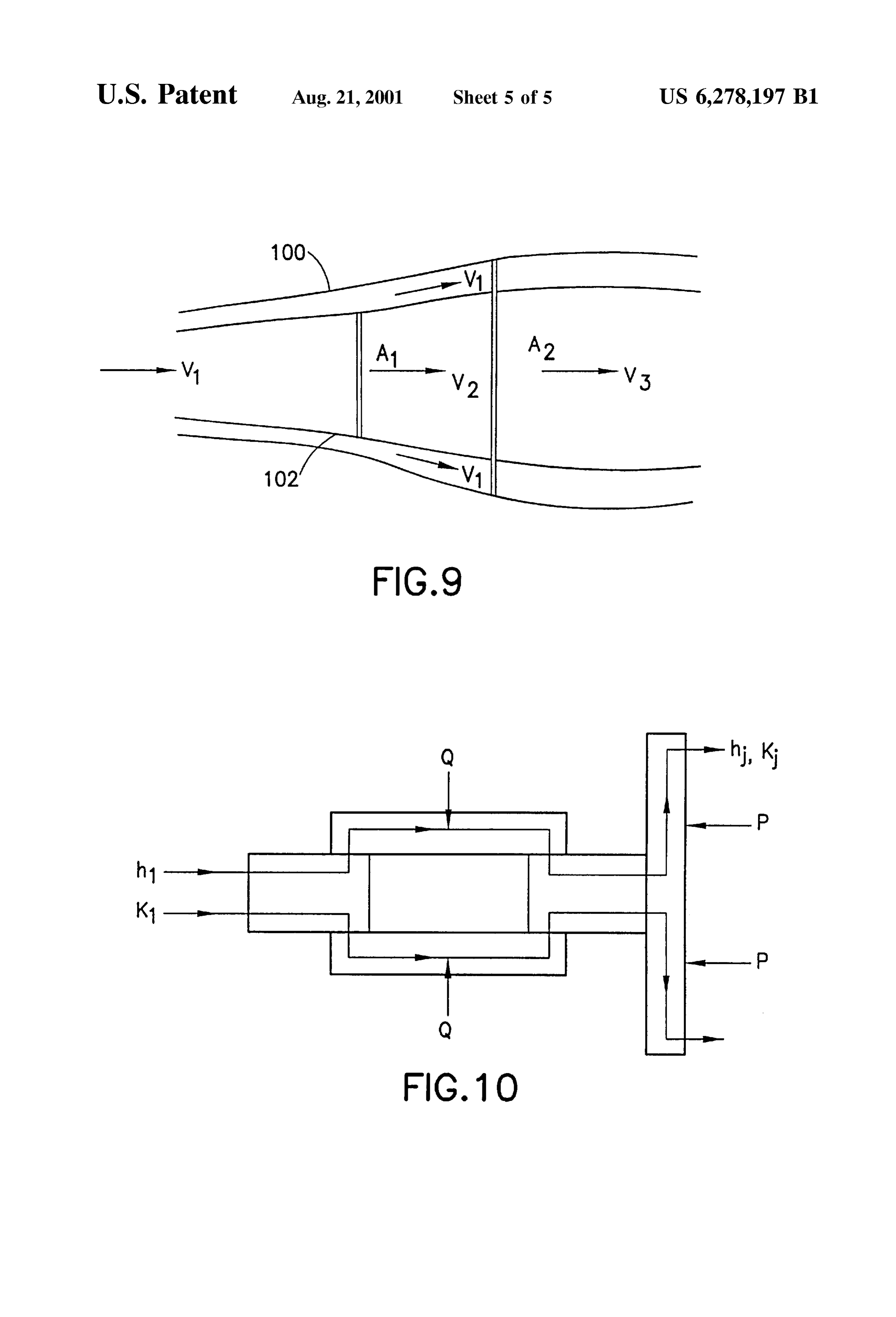
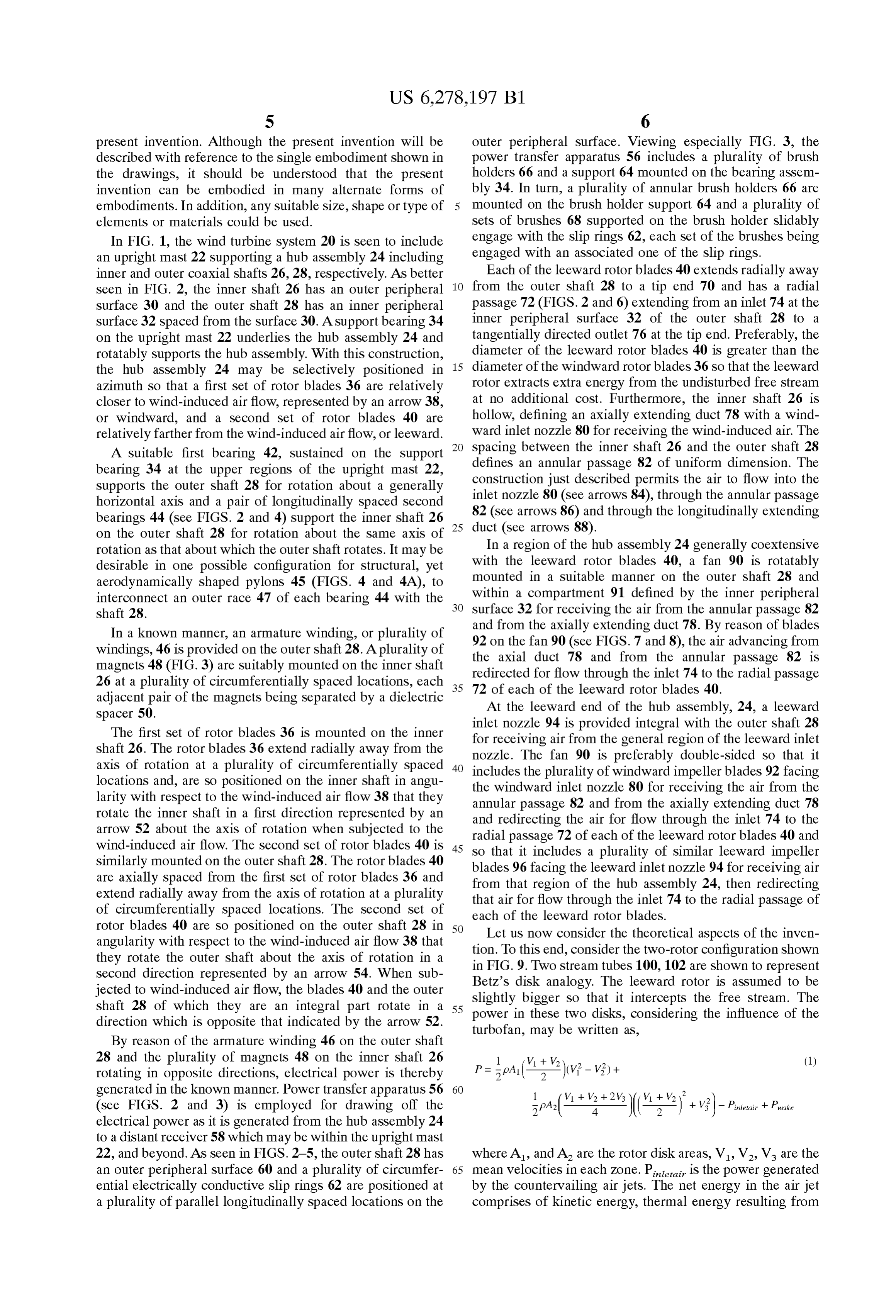
rotor blades 40 are so positioned on the outer shaft 28 in 50 Let us now consider the theoretical aspects of the inven angularity with respect to the wind-induced air flow 38 that they rotate the outer Shaft about the axis of rotation in a tion.in FIG.
To this end, consider the two-rotor configuration shown 9. Two stream tubes 100,102 are shown to represent second direction represented by an arrow 54. When Sub Betz's disk analogy. The leeward rotor is assumed to be jected to wind-induced air flow, the blades 40 and the outer Slightly shaft 28 of which they are an integral part rotate in a 55 power inbigger So that it intercepts the free Stream. The direction which is opposite that indicated by the arrow 52. turbofan, these two disks, considering the influence of the may be written as,
By reason of the armature winding 46 on the outer shaft 28 and the plurality of magnets 48 on the inner shaft 26 1 V + V2) 2 (1) rotating in opposite directions, electrical power is thereby P = pa ( 2)(vi - Vi)+ generated in the known manner. Power transfer apparatus 56 60 1 V1 + V2 + 2 V3 V + V (see FIGS. 2 and 3) is employed for drawing off the ipA: 4 ( 2 ) -- vi) - Pintelair + Pake electrical power as it is generated from the hub assembly 24 to a distant receiver 58 which may be within the upright mast 22, and beyond. As seen in FIGS. 2-5, the outer shaft 28 has where A, and A are the rotor disk areas, V, V, V are the an outer peripheral Surface 60 and a plurality of circumfer 65 mean Velocities in each Zone. Pei is the power generated ential electrically conductive Slip ringS 62 are positioned at by the countervailing air jets. The net energy in the air jet a plurality of parallel longitudinally Spaced locations on the comprises of kinetic energy, thermal energy resulting from
Page 10
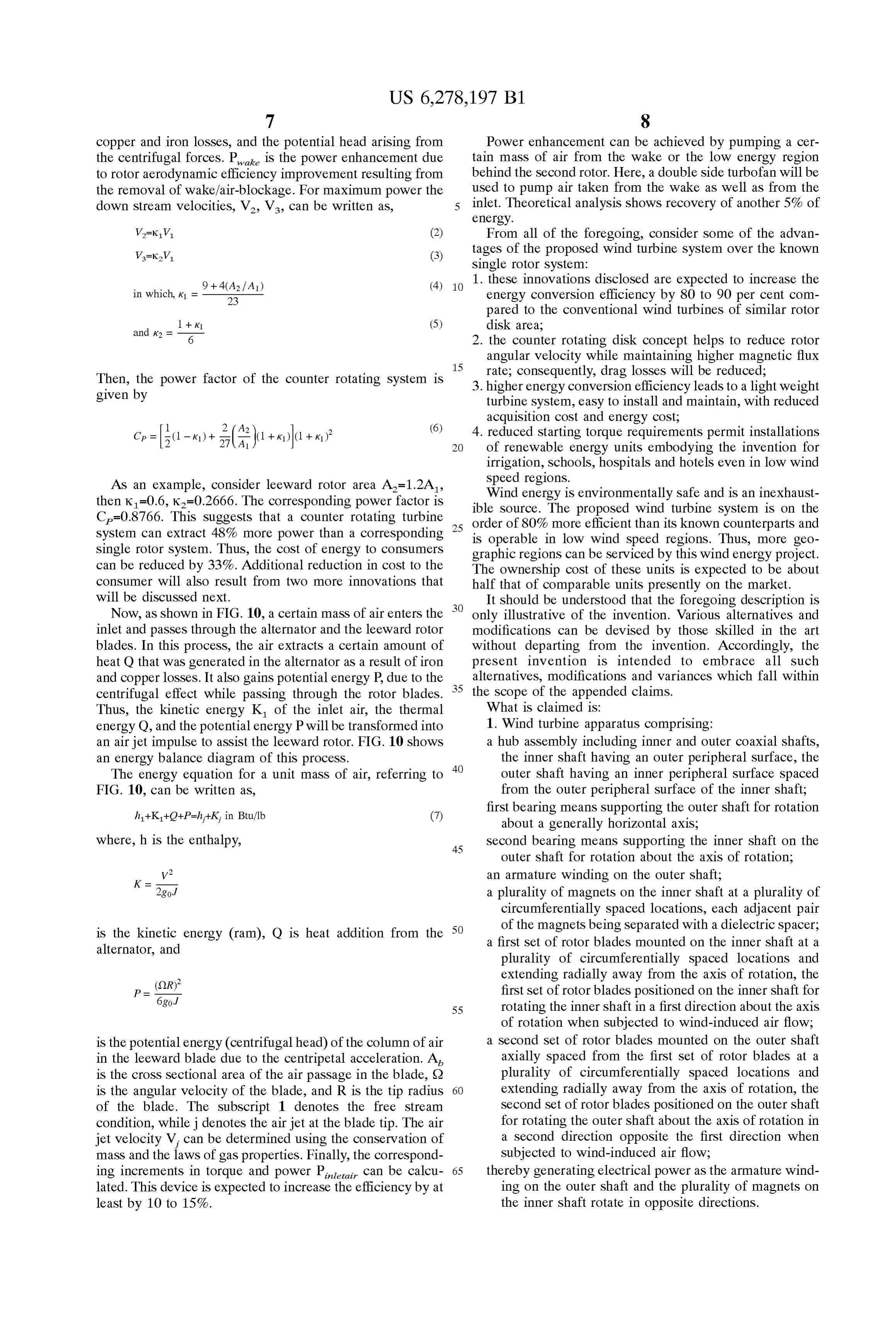
copper and iron losses, and the potential head arising from Power enhancement can be achieved by pumping a cer the centrifugal forces. P is the power enhancement due tain mass of air from the wake or the low energy region to rotor aerodynamic efficiency improvement resulting from behind the second rotor. Here, a double side turbofan will be the removal of wake/air-blockage. For maximum power the used to pump air taken from the wake as well as from the down Stream Velocities, V, V, can be written as, inlet. Theoretical analysis shows recovery of another 5% of energy.
V=kV (2) From all of the foregoing, consider Some of the advan V=kV (3) tages of the proposed wind turbine System over the known Single rotor System:
9 + 4(A2 f A 1) (4) 1. these innovations disclosed are expected to increase the in which, K1
- energy conversion efficiency by 80 to 90 per cent com pared to the conventional wind turbines of Similar rotor
1 + k, (5) disk area;
2. the counter rotating disk concept helps to reduce rotor angular Velocity while maintaining higher magnetic flux 15 rate, consequently, drag losses will be reduced;
Then, the power factor of the counter rotating System is 3. higher energy conversion efficiency leads to a light weight given by turbine System, easy to install and maintain, with reduced
acquisition cost and energy cost;
(6) 4. reduced Starting torque requirements permit installations
of renewable energy units embodying the invention for irrigation, Schools, hospitals and hotels even in low wind
As an example, consider leeward rotor area A=1.2A, Speed regions.
then K=0.6, Ka=0.2666. The corresponding power factor is ible Source. Wind energy is environmentally Safe and is an inexhaust C=0.8766. This Suggests that a counter rotating turbine 25 order of 80%The proposed wind turbine System is on the System can extract 48% more power than a corresponding is operable in low efficient more than its known counterparts and wind Speed regions. Thus, more geo
Single rotor System. Thus, the cost of energy to consumers graphic regions can be Serviced by this wind energy project. can be reduced by 33%. Additional reduction in cost to the The ownership cost of these units is expected to be about consumer will also result from two more innovations that half that of comparable units presently on the market. will be discussed next. It should be understood that the foregoing description is Now, as shown in FIG. 10, a certain mass of air enters the only illustrative of the invention. Various alternatives and inlet and passes through the alternator and the leeward rotor modifications can be devised by those skilled in the art blades. In this process, the air extracts a certain amount of without departing from the invention. Accordingly, the heat Q that was generated in the alternator as a result of iron present invention is intended to embrace all such and copper losses. It also gains potential energy P, due to the alternatives, modifications and variances which fall within centrifugal effect while passing through the rotor blades. 35 the Scope of the appended claims.
Thus, the kinetic energy K of the inlet air, the thermal What is claimed is:
energy Q, and the potential energy P will be transformed into 1. Wind turbine apparatus comprising: an air jet impulse to assist the leeward rotor. FIG. 10 shows a hub assembly including inner and outer coaxial Shafts, an energy balance diagram of this process. the inner Shaft having an outer peripheral Surface, the The energy equation for a unit mass of air, referring to 40 Outer Shaft having an inner peripheral Surface Spaced FIG. 10, can be written as, from the outer peripheral Surface of the inner Shaft;
first bearing means Supporting the Outer shaft for rotation about a generally horizontal axis, where, h is the enthalpy, 45
Second bearing means Supporting the inner shaft on the
Outer Shaft for rotation about the axis of rotation;
V2 an armature winding on the Outer Shaft; 2god a plurality of magnets on the inner shaft at a plurality of circumferentially spaced locations, each adjacent pair of the magnets being Separated with a dielectric Spacer, is the kinetic energy (ram), Q is heat addition from the 50 a first set of rotor blades mounted on the inner shaft at a alternator, and plurality of circumferentially spaced locations and
extending radially away from the axis of rotation, the
6 god first set of rotor blades positioned on the inner shaft for 55 rotating the inner Shaft in a first direction about the axis of rotation when subjected to wind-induced air flow;
is the potential energy (centrifugal head) of the column of air a Second Set of rotor blades mounted on the outer Shaft in the leeward blade due to the centripetal acceleration. A axially Spaced from the first Set of rotor blades at a is the croSS Sectional area of the air passage in the blade, S2 plurality of circumferentially spaced locations and is the angular Velocity of the blade, and R is the tip radius 60 extending radially away from the axis of rotation, the of the blade. The Subscript 1 denotes the free stream Second Set of rotor blades positioned on the Outer Shaft condition, while j denotes the air jet at the blade tip. The air for rotating the outer Shaft about the axis of rotation in jet velocity V, can be determined using the conservation of a Second direction opposite the first direction when mass and the laws of gas properties. Finally, the correspond Subjected to wind-induced air flow; ing increments in torque and power P can be calcu 65 thereby generating electrical power as the armature wind lated. This device is expected to increase the efficiency by at ing on the Outer shaft and the plurality of magnets on least by 10 to 15%. the inner Shaft rotate in opposite directions.
Page 11
2. Wind turbine apparatus as set forth in claim 1 includ 8. Wind turbine apparatus comprising: ing: a hub assembly including inner and outer coaxial Shafts, an upright mast; and the inner Shaft having an outer peripheral Surface, the Support bearings on the upright mast underlying the hub Outer Shaft having an inner peripheral Surface Spaced assembly for rotatably Supporting the hub assembly from the outer peripheral Surface of the inner Shaft; enabling it to be Selectively positioned in azimuth So first bearing means Supporting the Outer shaft for rotation that the first set of rotor blades are relatively closer to about a generally horizontal axis, the wind-induced air flow, or windward, and the Second Second bearing means Supporting the inner shaft on the set of rotor blades are relatively farther from the Outer Shaft for rotation about the axis of rotation; wind-induced air flow, or leeward. a first set of rotor blades mounted on the inner shaft at a 3. Wind turbine apparatus as set forth in claim 2 includ plurality of circumferentially spaced locations and ing: extending radially away from the axis of rotation, the power transfer means for drawing off the electrical power first set of rotor blades positioned on the inner shaft for from the hub assembly to a distant receiver. 15 rotating the inner Shaft in a first direction about the axis 4. Wind turbine apparatus as set forth in claim 3 of rotation when subjected to wind-induced air flow; wherein the outer Shaft has an Outer peripheral Surface and and a plurality of circumferential electrically conductive a Second Set of rotor blades mounted on the outer Shaft slip rings positioned at a plurality of parallel longitu axially Spaced from the first Set of rotor blades at a dinally Spaced locations thereon, and plurality of circumferentially spaced locations and wherein the power transfer means includes: extending radially away from the axis of rotation, the a brush holder Support mounted on the upright mast; Second Set of rotor blades positioned on the Outer Shaft an annular brush holder mounted on the brush holder for rotating the outer Shaft about the axis of rotation in
Support; and a Second direction opposite the first direction when 25 Subjected to wind-induced air flow.
a plurality of sets of brushes Supported on the brush holder 9. Wind turbine apparatus as set forth in claim 8 includ slidably engaged with the Slip rings, each Set of brushes ing:
engaged with an associated one of the Slip rings. an upright mast; and 5. Wind turbine apparatus as set forth in claim 1 Support bearings on the upright mast underlying the hub wherein each of the leeward rotor blades extends from the assembly for rotatably Supporting the hub assembly outer Shaft to a tip end and has a radial passage enabling it to be Selectively positioned in azimuth So extending from an inlet at the inner peripheral Surface that the first set of rotor blades are relatively closer to of the outer shaft to a tangentially directed outlet at the the Wind-induced air flow, or Windward, and the Second tip end; set of rotor blades are relatively farther from the wherein the Spacing between the inner Shaft and the outer 35 wind-induced air flow, or leeward. shaft defines an annular passage of uniform dimension; 10. Wind turbine apparatus as set forth in claim 9 includ and ing:
wherein the inner shaft is hollow and defines an axially power transfer means for drawing off the electrical power extending duct; and including: from the hub assembly to a distant receiver. a windward inlet nozzle for receiving wind-induced air 40 11. Wind turbine apparatus as set forth in claim 10 and permitting the air to flow through the annular wherein the outer shaft has an Outer peripheral Surface and passage and through the longitudinally extending duct; a plurality of circumferential electrically conductive and slip rings positioned at a plurality of parallel longitu a fan for receiving the air from the annular passage and 45 dinally Spaced locations thereon, and from the axially extending duct and redirecting the air wherein the power transfer means includes: for flow through the inlet to the radial passage of each a brush holder Support mounted on the upright mast; of the leeward rotor blades. an annular brush holder mounted on the brush holder 6. Wind turbine apparatus as set forth in claim 5 includ Support; and ing: 50 a plurality of sets of brushes Supported on the brush holder a leeward inlet nozzle integral with the outer shaft for slidably engaged with the Slip rings, each Set of brushes receiving air at the leeward end of the hub assembly; engaged with an associated one of the Slip rings. and 12. Wind turbine apparatus as set forth in claim 8 wherein the fan is double-sided including a plurality of wherein each of the leeward rotor blades extends from the windward impeller blades facing the windward inlet 55 Outer shaft to a tip end and has a radial passage nozzle for receiving the air from the annular passage extending from an inlet at the inner peripheral Surface and from the axially extending duct and redirecting the of the outer Shaft to a tangentially directed outlet at the air for flow through the inlet to the radial passage of tip end;
each of the leeward rotor blades and a plurality of wherein the Spacing between the inner shaft and the outer leeward impellerblades facing the leeward inlet nozzle 60 shaft defines an annular passage of uniform dimension; for receiving air from the leeward inlet nozzle and and redirecting the air for flow through the inlet to the radial wherein the inner shaft is hollow and defines an axially passage of each of the leeward rotor blades. extending duct; and including:
7. Wind turbine apparatus as set forth in claim 5 a windward inlet nozzle for receiving wind-induced air wherein the diameter of the set of leeward rotor blades is 65 and permitting the air to flow through the annular greater than the diameter of the set of windward rotor passage and through the longitudinally extending duct; blades. and
Page 12
a fan for receiving the air from the annular passage and the armature winding on the outer Shaft and the plu from the axially extending duct and redirecting the air rality of magnets on the inner Shaft rotate in opposite for flow through the inlet to the radial passage of each directions.
of the leeward rotor blades. 15. A method of generating power as Set forth in claim 14 13. A method of generating power comprising the Steps 5 including the Steps of:
(h) providing each of the leeward rotor blades with a (a) providing a hub assembly including inner and outer radial passage extending from an inlet at the inner coaxial shafts, the inner shaft having an outer periph peripheral Surface of the Outer shaft to a tangentially eral Surface, the outer shaft having an inner peripheral directed outlet at the tip end; Surface Spaced from the outer peripheral Surface of the inner Shaft; (i) providing an annular passage of uniform dimension (b) mounting a first set of rotor blades on the inner shaft between the inner shaft and the outer shaft; and at a plurality of circumferentially spaced locations So as (j) providing an axially extending duct through the inner to extend radially away from the axis of rotation; shaft, and
(c) mounting a second set of rotor blades on the outer (k) receiving wind-induced air through a windward inlet shaft axially spaced from the first set of rotor blades at nozzle and permitting the air to flow through the a plurality of circumferentially spaced locations So as to annular passage and through the longitudinally extend extend radially away from the axis of rotation; and ing duct and redirecting the air for flow through the (d) positioning the first and Second sets of rotor blades So inlet to the radial passage of each of the leeward rotor that wind-induced air flow causes the first set of blades blades.
to rotate with the inner shaft in a first direction and so 16. A method of generating power as set forth in claim 15 that wind-induced air flow causes the Second Set of including the Step of:
blades to rotate with the outer shaft in a second direc (1) receiving air at the leeward end of the hub assembly tion opposite the first direction. 25 and redirecting the air for flow through the inlet to the 14. A method of generating power as Set forth in claim 13 radial passage of each of the leeward rotor blades. including the Steps of: 17. A method of generating power as Set forth in claim 14 (e) providing an armature winding on the outer shaft; including the Step of:
(f) providing a plurality of magnets on the inner shaft at (h) drawing off the electrical power from the hub assem a plurality of circumferentially Spaced locations, bly to a distant receiver.
(g) Separating each adjacent pair of the magnets with a dielectric spacer thereby generating electrical power as k k k k k
Provenance
- Collection
- Cited prior art
- Original PDF
- patentimages.storage.googleapis.com →
- Filed
- 2000-02-05
- Pages
- 12
- Method
- pdftotext (the PDF's own text layer) + pdftoppm 300dpi page scans
- Source
- Google Patents bibliographic record
- Granted
- 2001-08-21
- Inventors
- Kari Appa
- Transcribed from
- patentimages.storage.googleapis.com →