patent · US5704567
Blade de-icer for rotary wing aircraft
6 January 1998
Page 1 — bibliographic record
United States Patent (19) 11 Patent Number: 5,704,567 Maglieri 45 Date of Patent: Jan. 6, 1998 54) BLADE DE-CER FOR ROTARY WING FOREIGN PATENT DOCUMENTS AIRCRAFT 863490 4/1941 France ............................... 244/134 D John Michael Maglieri, Williamsburg, 228.1273 3/1976 France .............................. 244/134 D (75) Inventor:
73 Assignee: The United States of America as Primary Examiner-William Grant represented by the Secretary of the Attorney, Agent, or Firm-Arthur H. Tischer; John H. Army, Washington, D.C. Lamming; Freddie M. Bush
22 Filed: Oct. 16, 1995 A blade de-icer for rotary wing aircraft comprises magnets placed around the rotor mast and coils with laminated plates 51 int.C. ... B64D 15/12 installed at the blade cuff of each rotor blade, in sufficient 52) U.S. C. .................................. 244/17.11; 24.4/134 D proximity to produce a high voltage, high current pulse 58 Field of Search ............................. 244/17.11, 134 D; every time a magnet and a coil pass each other while the 200/61.19; 310/254, 261 rotor is turning. Electrically conductive cable or wire carries the current down each rotor blade to heating elements which 56) References Cited melt any accreted ice on the blade. In one embodiment,
magnets are used. In each embodiment, difficult switches for 2,429,061 10/1947 Hunter ................................ 244/134 D turning the de-icer on and off are provided. 2,444,557 7/1948 Eaton .................................. 244/34. D 2,491,172 12/1949 Forsyth .......... 244134 DX 2,678,181 5/1954 Geyer et al. ........................ 244f134 D 9 Claims, 7 Drawing Sheets
Page 2
Drawing sheet — no readable text.
Page 3
Drawing sheet — no readable text.
Page 4
Drawing sheet — no readable text.
Page 5
Drawing sheet — no readable text.
Page 6
Drawing sheet — no readable text.
Page 7
Drawing sheet — no readable text.
Page 8
Drawing sheet — no readable text.
Page 9
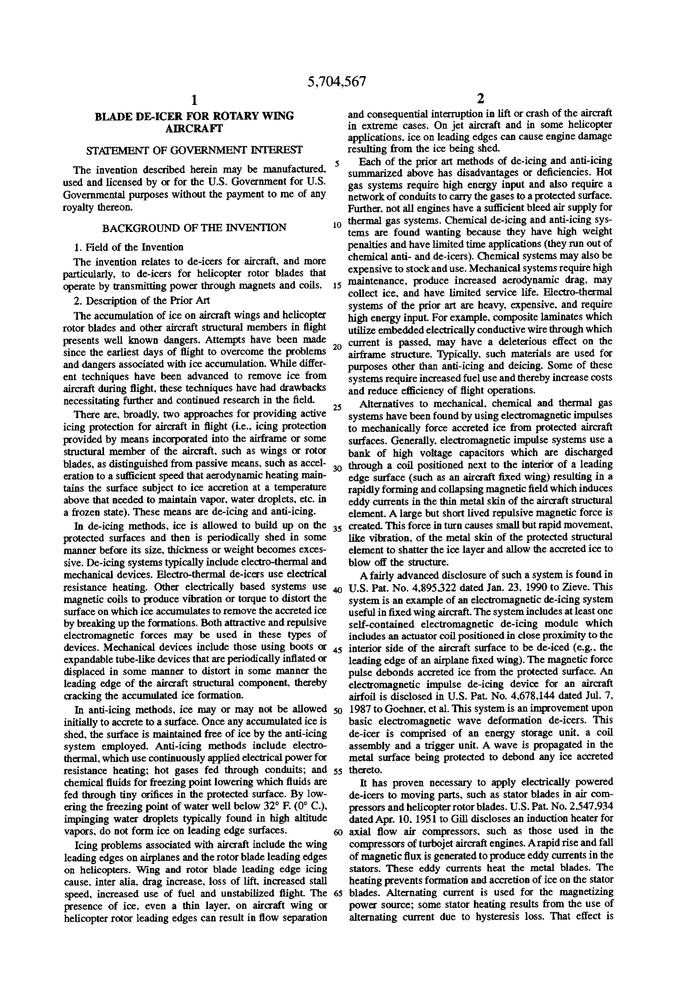
BLADE DE-CER FOR ROTARY WING and consequential interruption in lift or crash of the aircraft ARCRAFT in extreme cases. On jet aircraft and in some helicopter applications, ice on leading edges can cause engine damage
STATEMENT OF GOVERNMENT INTEREST resulting from the ice being shed, s Each of the prior art methods of de-icing and anti-icing
The invention described herein may be manufactured, summarized above has disadvantages or deficiencies. Hot used and licensed by or for the U.S. Government for U.S. gas systems require high energy input and also require a Governmental purposes without the payment to me of any network of conduits to carry the gases to a protected surface. royalty thereon. Further, not all engines have a sufficient bleed air supply for BACKGROUND OF THE INVENTION 10 thermal gas systems. Chemical de-icing and anti-icing sys tems are found wanting because they have high weight 1. Field of the Invention penalties and have limited time applications (they run out of The invention relates to de-icers for aircraft, and more chemical anti- and de-icers). Chemical systems may also be particularly, to de-icers for helicopter rotor blades that expensive maintenance, to stock and use. Mechanical systems require high produce increased aerodynamic drag, may operate by transmitting power through magnets and coils. 15 collect ice, and have limited service life. Electro-thermal 2. Description of the Prior Art systems of the prior art are heavy, expensive, and require The accumulation of ice on aircraft wings and helicopter high energy input. For example, composite laminates which rotor blades and other aircraft structural members in flight utilize embedded electrically conductive wire through which presents well known dangers. Attempts have been made current is passed, may have a deleterious effect on the since the earliest days of flight to overcome the problems airframe structure. Typically, such materials are used for and dangers associated with ice accumulation. While differ purposes other than anti-icing and deicing. Some of these ent techniques have been advanced to remove ice from systems require increased fuel use and thereby increase costs aircraft during flight, these techniques have had drawbacks and reduce efficiency of flight operations. necessitating further and continued research in the field. 25 Alternatives to mechanical, chemical and thermal gas There are, broadly, two approaches for providing active systems have been found by using electromagnetic impulses icing protection for aircraft in flight (i.e., icing protection to mechanically force accreted ice from protected aircraft provided by means incorporated into the airframe or some surfaces. Generally, electromagnetic impulse systems use a structural member of the aircraft, such as wings or rotor bank of high voltage capacitors which are discharged blades, as distinguished from passive means, such as accel 30 through a coil positioned next to the interior of a leading eration to a sufficient speed that aerodynamic heating main edge surface (such as an aircraft fixed wing) resulting in a tains the surface subject to ice accretion at a temperature rapidly forming and collapsing magnetic field which induces above that needed to maintain vapor, water droplets, etc. in eddy currents in the thin metal skin of the aircraft structural a frozen state). These means are de-icing and anti-icing. element. A large but short lived repulsive magnetic force is In de-icing methods, ice is allowed to build up on the 35 created. This force in turn causes small but rapid movement, protected surfaces and then is periodically shed in some like vibration, of the metal skin of the protected structural manner before its size, thickness or weight becomes exces element to shatter the ice layer and allow the accreted ice to sive. De-icing systems typically include electro-thermal and blow off the structure.
mechanical devices. Electro-thermal de-icers use electrical Afairly advanced disclosure of such a system is found in resistance heating. Other electrically based systems use U.S. Pat. No. 4,895.322 dated Jan. 23, 1990 to Zieve. This magnetic coils to produce vibration or torque to distort the system is an example of an electromagnetic de-icing system surface on which ice accumulates to remove the accreted ice useful infixed wing aircraft. The system includes at least one by breaking up the formations. Both attractive and repulsive self-contained electromagnetic de-icing module which electromagnetic forces may be used in these types of includes an actuator coil positioned in close proximity to the devices. Mechanical devices include those using boots or 45 interior side of the aircraft surface to be de-iced (e.g., the expandable tube-like devices that are periodically inflated or leading edge of an airplane fixed wing). The magnetic force displaced in some manner to distort in some manner the pulse debonds accreted ice from the protected surface. An leading edge of the aircraft structural component, thereby electromagnetic impulse de-icing device for an aircraft cracking the accumulated ice formation. airfoil is disclosed in U.S. Pat. No. 4,678,144 dated Jul. 7, In anti-icing methods, ice may or may not be allowed SO 1987 to Goehner, et al. This system is an improvement upon initially to accrete to a surface. Once any accumulated ice is basic electromagnetic wave deformation de-icers. This shed, the surface is maintained free of ice by the anti-icing de-icer is comprised of an energy storage unit, a coil system employed. Anti-icing methods include electro assembly and a trigger unit. A wave is propagated in the thermal, which use continuously applied electrical powerfor metal surface being protected to debond any ice accreted resistance heating; hot gases fed through conduits; and 55 thereto.
chemical fluids for freezing point lowering which fluids are It has proven necessary to apply electrically powered fed through tiny orifices in the protected surface. By low de-icers to moving parts, such as stator blades in air com ering the freezing point of water well below 32° F (0° C.), pressors and helicopter rotor blades. U.S. Pat No. 2,547.934 impinging water droplets typically found in high altitude dated Apr. 10, 1951 to Gill discloses an induction heater for vapors, do not form ice on leading edge surfaces. axial flow air compressors, such as those used in the Icing problems associated with aircraft include the wing compressors of turbojet aircraft engines. A rapid rise and fall leading edges on airplanes and the rotor blade leading edges of magnetic flux is generated to produce eddy currents in the on helicopters. Wing and rotor blade leading edge icing stators. These eddy currents heat the metal blades. The cause, inter alia, drag increase, loss of lift, increased stall heating prevents formation and accretion of ice on the stator speed, increased use of fuel and unstabilized flight. The 65 blades. Alternating current is used for the magnetizing presence of ice, even a thin layer, on aircraft wing or power source; some stator heating results from the use of helicopter rotor leading edges can result in flow separation alternating current due to hysteresis loss. That effect is
Page 10
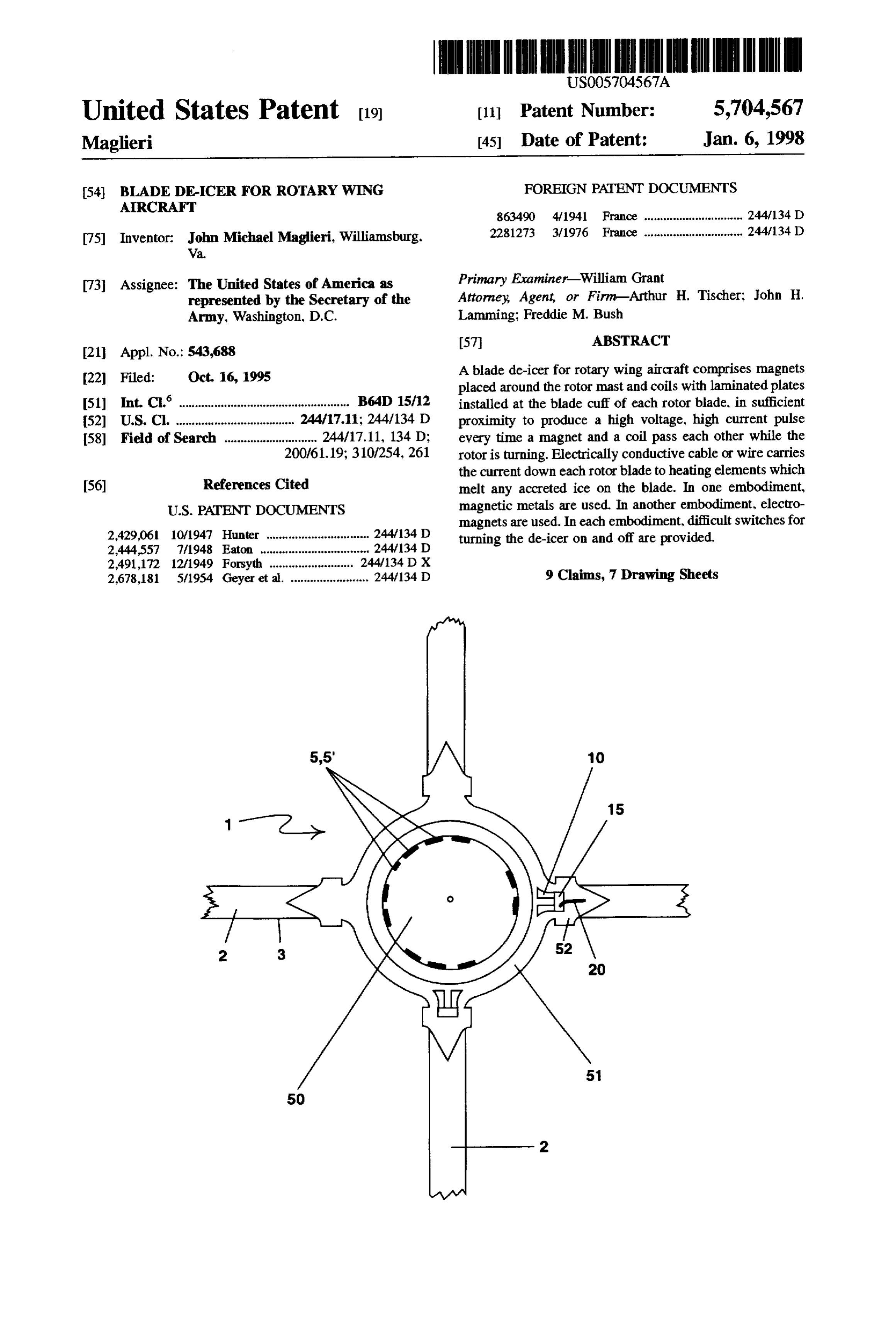
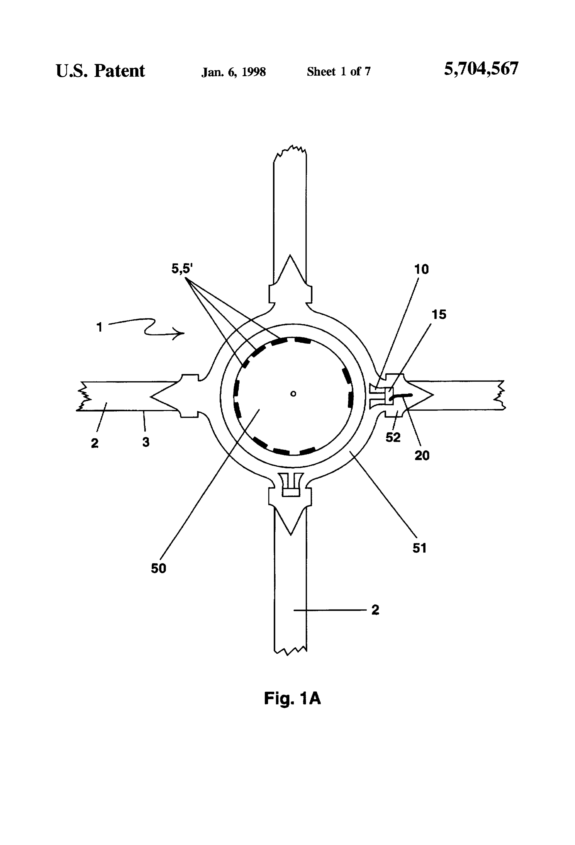
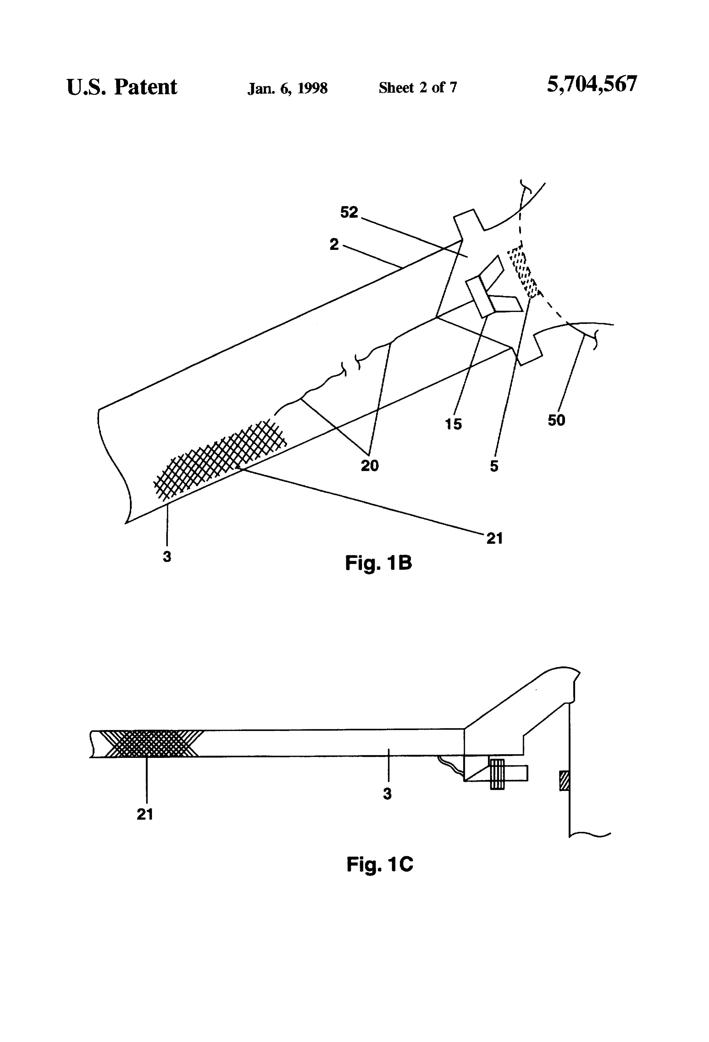
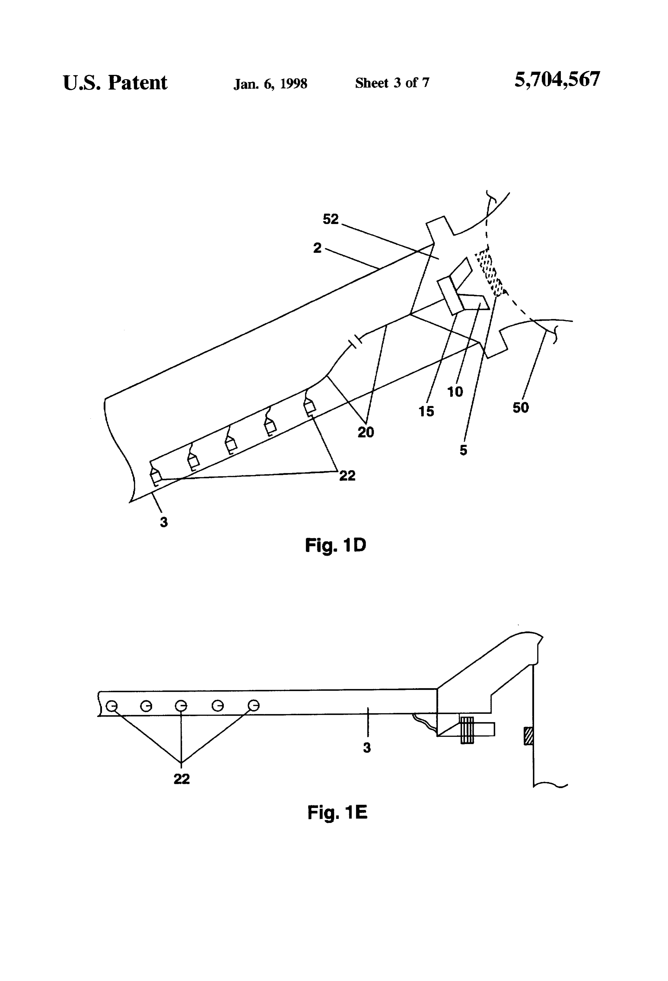
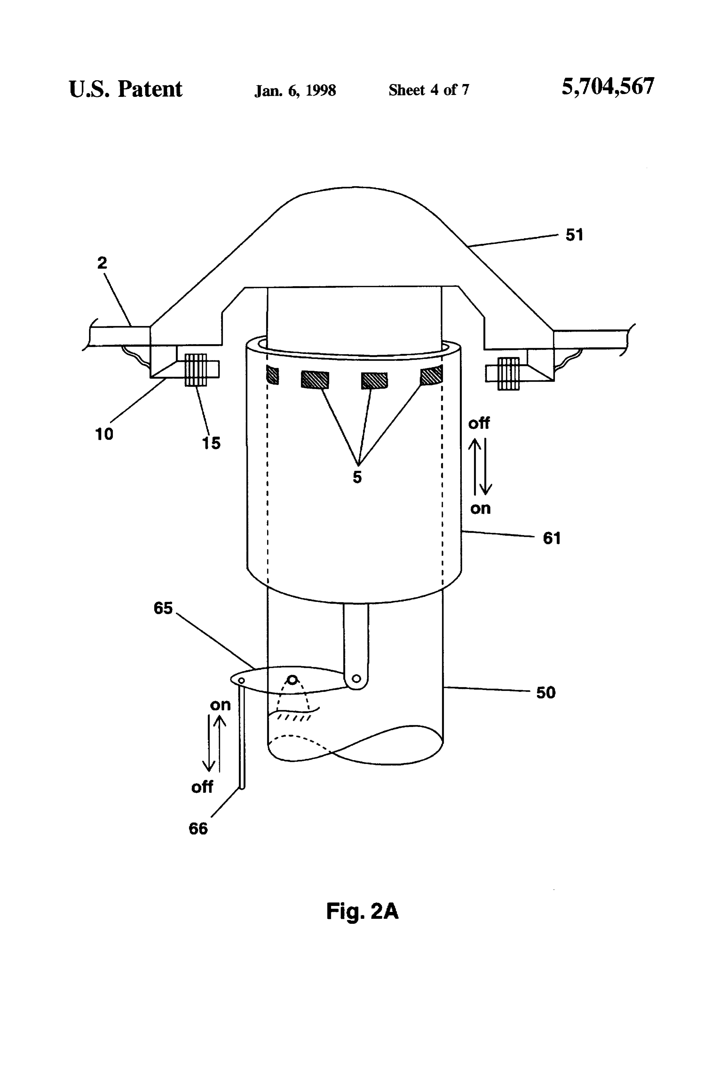
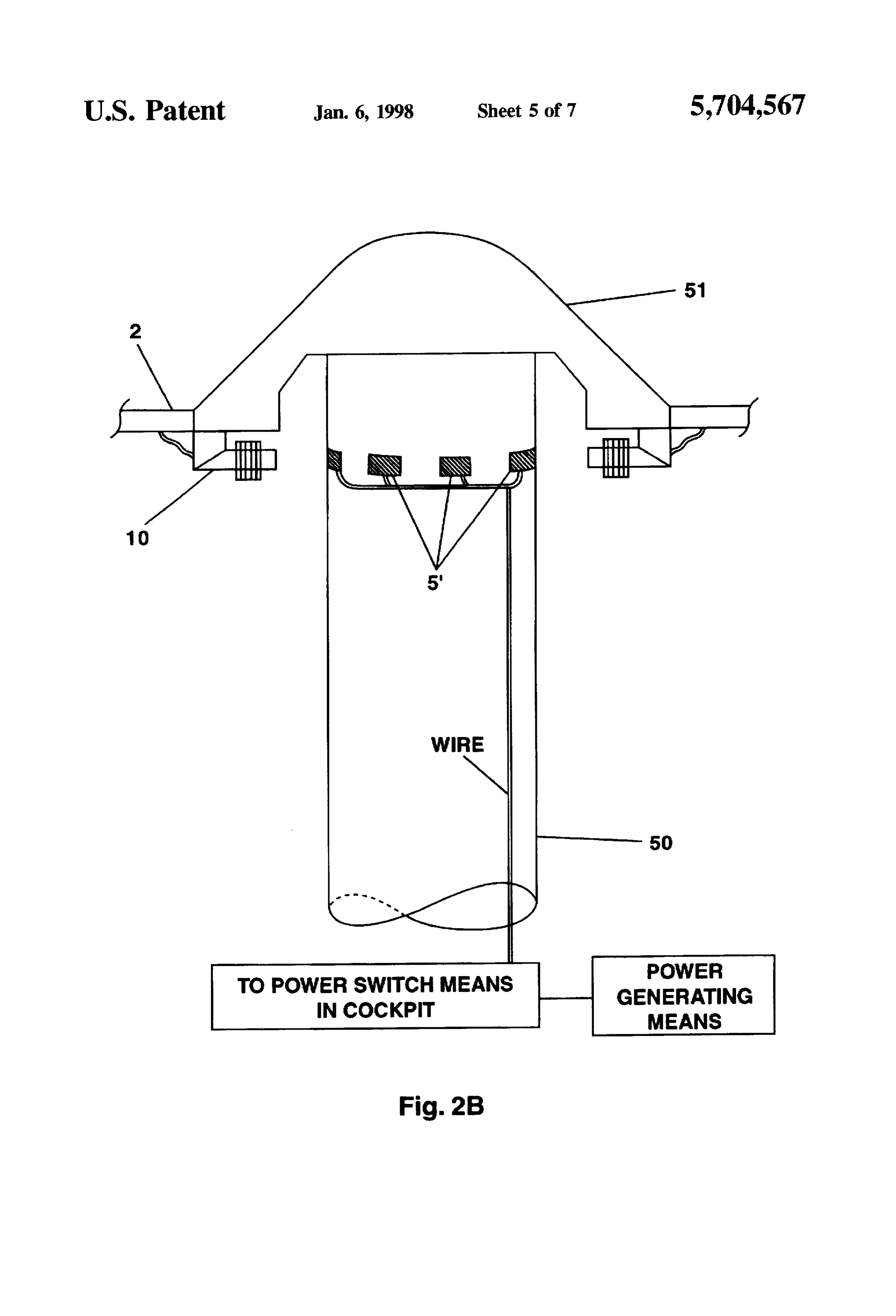
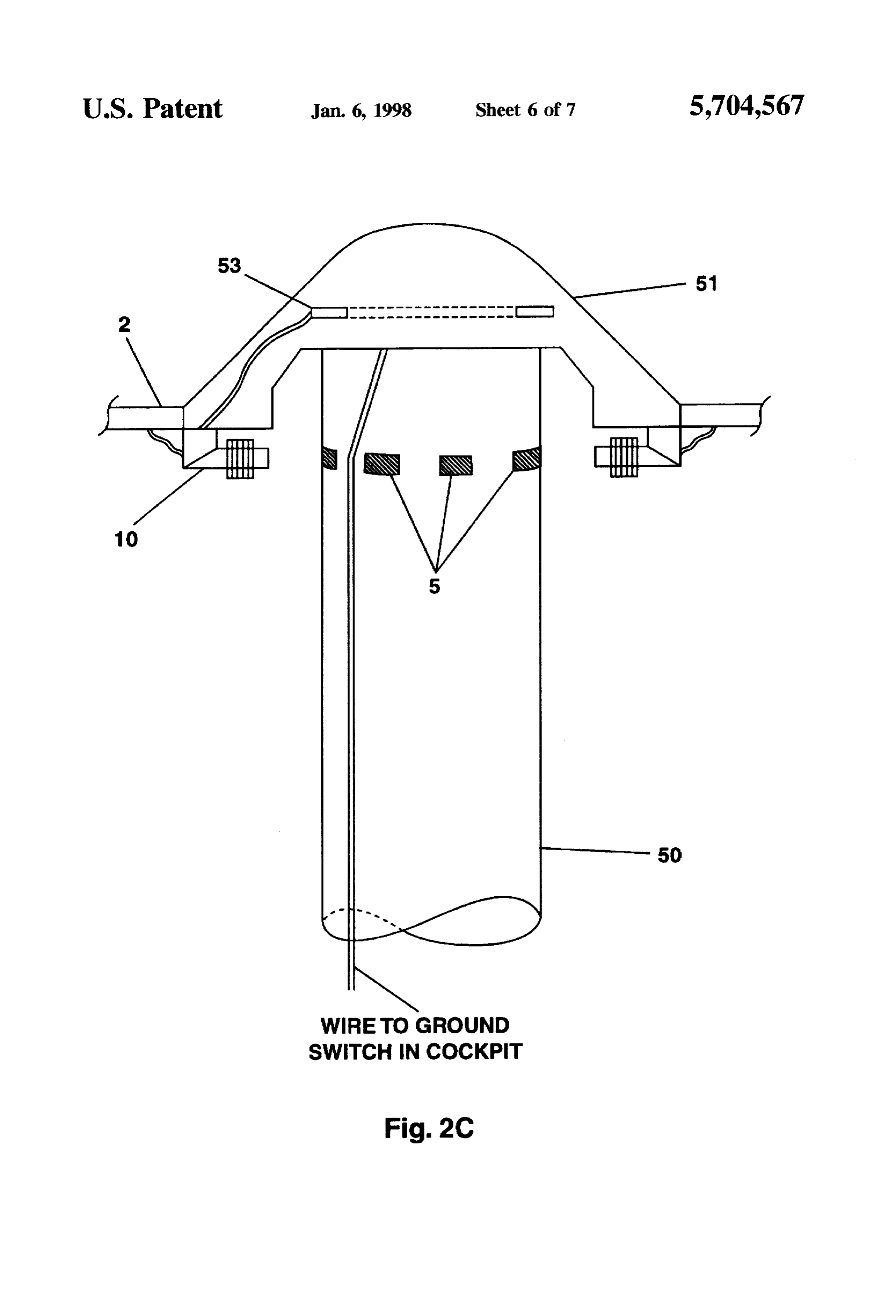
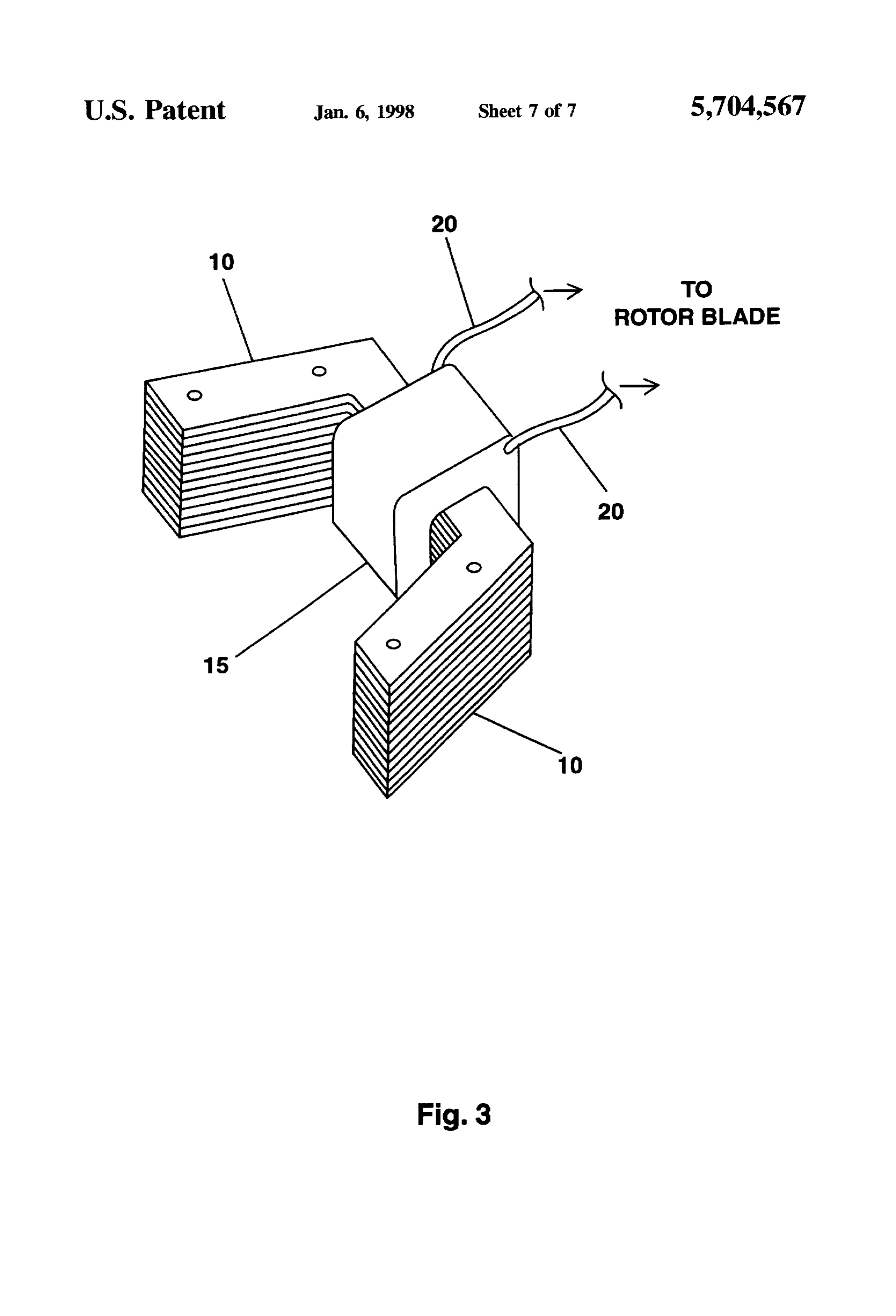
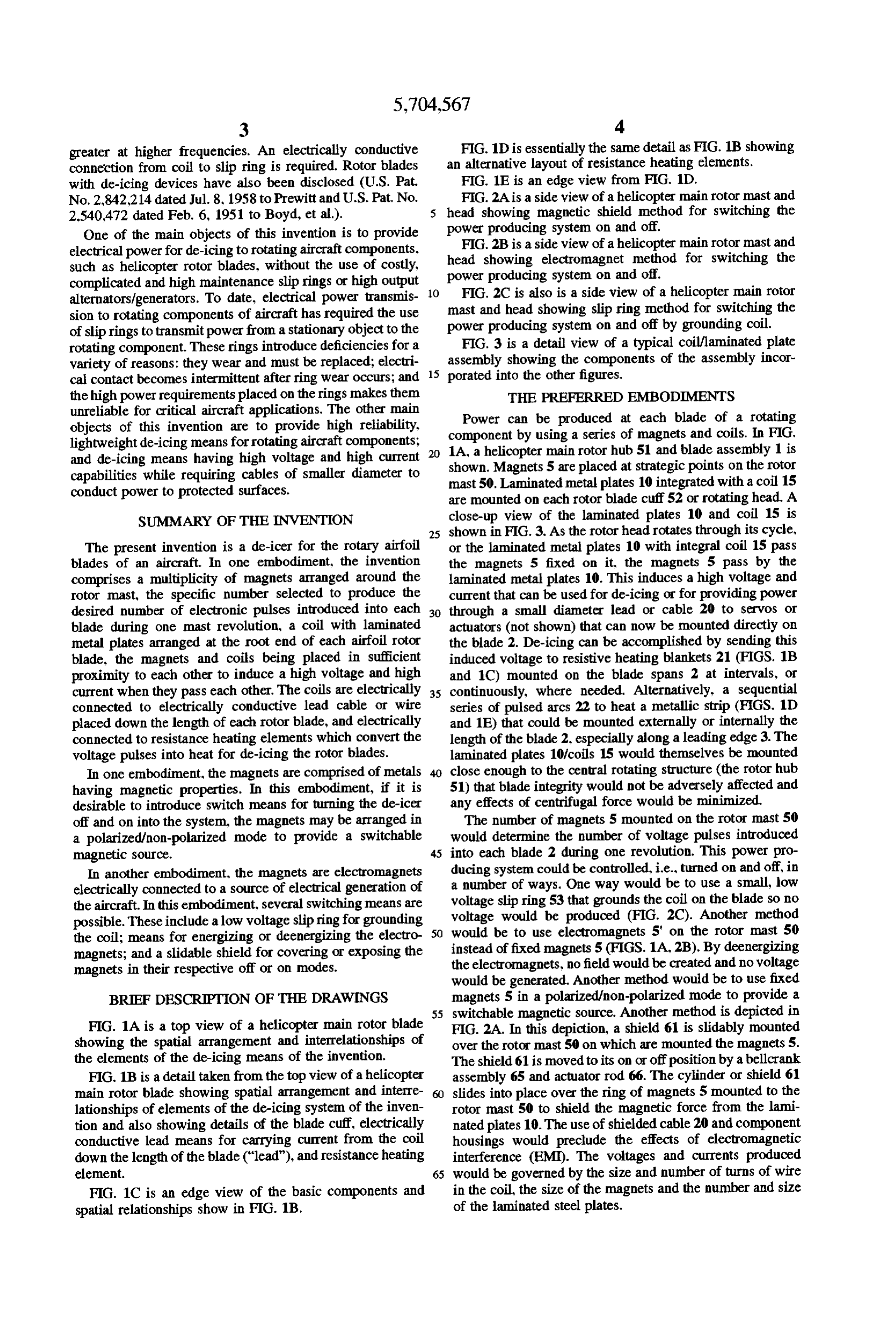
greater at higher frequencies. An electrically conductive FIG. 1D is essentially the same detail as FIG. 1B showing connection from coil to slip ring is required. Rotor blades an alternative layout of resistance heating elements. with de-icing devices have also been disclosed (U.S. Pat. FIG. 1E is an edge view from FIG. 1D. No. 2,842,214 dated Jul. 8, 1958 to Prewitt and U.S. Pat. No. FIG. 2A is a side view of a helicopter main rotor mast and 2.540.472 dated Feb. 6, 1951 to Boyd, et al.). head showing magnetic shield method for switching the One of the main objects of this invention is to provide power producing system on and off. electrical power for de-icing to rotating aircraft components. head FIG.2B is a side view of a helicopter main rotor mast and such as helicopter rotor blades, without the use of costly, showing electromagnet method for switching the complicated and high maintenance slip rings or high output 10 power producing system on and off. alternators/generators. To date, electrical power transmis FIG. 2C is also is a side view of a helicopter main rotor sion to rotating components of aircraft has required the use power mast and head showing slip ring method for switching the of slip rings to transmit power from a stationary object to the producing system on and off by grounding coil. rotating component. These rings introduce deficiencies for a FIG. 3 is a detail view of a typical coil?laminated plate variety of reasons: they wear and must be replaced; electri 15 assembly showing the components of the assembly incor cal contact becomes intermittent after ring wear occurs; and porated into the other figures.
the high power requirements placed on the rings makes them THE PREFERRED EMBODIMENTS unreliable for critical aircraft applications. The other main objects of this invention are to provide high reliability. componentcanPower be produced at each blade of a rotating lightweight de-icing means for rotating aircraft components; 20 1A, a helicopter maina rotor by using series of magnets and coils. In FIG.
and de-icing means having high voltage and high current shown. Magnets 5 are placedhub at 51 and blade assembly 1 is strategic points on the rotor capabilities while requiring cables of smaller diameter to mast50. Laminated metal plates 10 integrated with a coil 15 conduct power to protected surfaces. are mounted on each rotor blade cuff 52 or rotating head. A SUMMARY OF THE INVENTION close-up view of the laminated plates 10 and coil 15 is 25 shown in FIG. 3. As the rotor head rotates through its cycle,
The present invention is a de-icer for the rotary airfoil or the laminated metal plates 10 with integral coil 15 pass blades of an aircraft. In one embodiment, the invention the magnets 5 fixed on it, the magnets 5 pass by the comprises a multiplicity of magnets arranged around the laminated metal plates 10. This induces a high voltage and rotor mast, the specific number selected to produce the current that can be used for de-icing or for providing power desired number of electronic pulses introduced into each 30 through a small diameter lead or cable 20 to servos or blade during one mast revolution, a coil with laminated actuators (not shown) that can now be mounted directly on metal plates arranged at the root end of each airfoil rotor the blade 2. De-icing can be accomplished by sending this blade, the magnets and coils being placed in sufficient induced voltage to resistive heating blankets 21 (FIGS. 1B proximity to each other to induce a high voltage and high and 1C) mounted on the blade spans 2 at intervals, or current when they pass each other. The coils are electrically 35 continuously, where needed. Alternatively, a sequential connected to electrically conductive lead cable or wire series of pulsed arcs 22 to heat a metallic strip (FIGS. 1D placed down the length of each rotor blade, and electrically and 1E) that could be mounted externally or internally the connected to resistance heating elements which convert the length of the blade 2. especially along a leading edge 3. The voltage pulses into heat for de-icing the rotor blades. laminated plates 10/coils 15 would themselves be mounted In one embodiment, the magnets are comprised of metals close enough to the central rotating structure (the rotor hub having magnetic properties. In this embodiment, if it is 51) that blade integrity would not be adversely affected and desirable to introduce switch means for turning the de-icer any effects of centrifugal force would be minimized. off and on into the system, the magnets may be arranged in The number of magnets 5 mounted on the rotor mast 50 a polarized/non-polarized mode to provide a switchable would determine the number of voltage pulses introduced magnetic source. 45 into each blade 2 during one revolution. This power pro In another embodiment, the magnets are electromagnets ducing system could be controlled, i.e., turned on and off, in electrically connected to a source of electrical generation of a number of ways. One way would be to use a small, low the aircraft. In this embodiment, several switching means are voltage slip ring 53 that grounds the coil on the blade so no possible. These include a low voltage slip ring for grounding voltage would be produced (FIG. 2C). Another method the coil; means for energizing or deemergizing the electro 50 would be to use electromagnets 5' on the rotor mast 50 magnets; and a slidable shield for covering or exposing the instead of fixed magnets 5 (FIGS. 1A, 2B). By deemergizing magnets in their respective off or on modes. the electromagnets, no field would be created and no voltage would be generated. Another method would be to use fixed
BRIEF DESCRIPTION OF THE DRAWINGS magnets 5 in a polarized/non-polarized mode to provide a 55 switchable magnetic source. Another method is depicted in
FIG. 1A is a top view of a helicopter main rotor blade FIG. 2A. In this depiction, a shield 61 is slidably mounted showing the spatial arrangement and interrelationships of over the rotor mast 50 on which are mounted the magnets 5. the elements of the de-icing means of the invention. The shield 61 is moved to its on or offposition by a bellcrank FIG. 1B is a detail taken from the top view of a helicopter assembly 65 and actuator rod 66. The cylinder or shield 61 main rotor blade showing spatial arrangement and interre slides into place over the ring of magnets 5 mounted to the lationships of elements of the de-icing system of the inven rotor mast 50 to shield the magnetic force from the lami tion and also showing details of the blade cuff, electrically nated plates 10. The use of shielded cable 20 and component conductive lead means for carrying current from the coil housings would preclude the effects of electromagnetic down the length of the blade ("lead"), and resistance heating interference (EMI). The voltages and currents produced element. 65 would be governed by the size and number of turns of wire FIG. 1C is an edge view of the basic components and in the coil, the size of the magnets and the number and size spatial relationships show in FIG. 1B. of the laminated steel plates.
Page 11
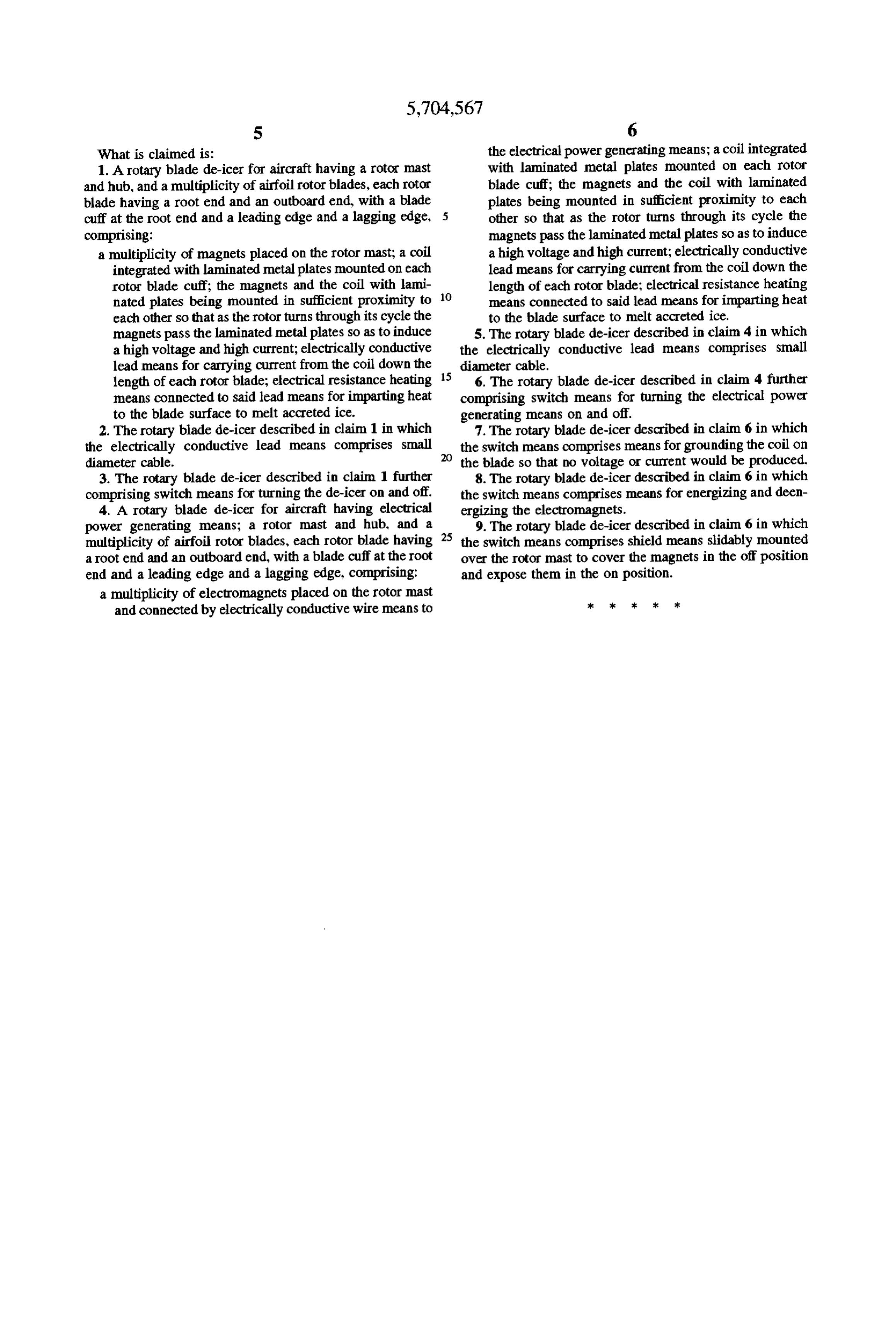
What is claimed is: the electrical power generating means; a coil integrated 1. A rotary blade de-icer for aircraft having a rotor mast with laminated metal plates mounted on each rotor and hub, and a multiplicity of airfoil rotor blades, each rotor blade cuff; the magnets and the coil with laminated blade having a root end and an outboard end, with a blade plates being mounted in sufficient proximity to each cuff at the root end and a leading edge and a lagging edge, other so that as the rotor turns through its cycle the comprising: magnets pass the laminated metal plates so as to induce a multiplicity of magnets placed on the rotor mast; a coil a high voltage and high current; electrically conductive integrated with laminated metal plates mounted on each lead means for carrying current from the coil down the rotor blade cuff; the magnets and the coil with lami 10 length of each rotor blade; electrical resistance heating nated plates being mounted in sufficient proximity to means connected to said lead means for imparting heat each other so that as the rotor turns through its cycle the to the blade surface to melt accreted ice. magnets pass the laminated metal plates so as to induce 5. The rotary blade de-icer described in claim 4 in which a high voltage and high current; electrically conductive the electrically conductive lead means comprises small lead means for carrying current from the coil down the diameter cable.
length of each rotor blade; electrical resistance heating 15 6. The rotary blade de-icer described in claim 4 further means connected to said lead means for imparting heat comprising switch means for turning the electrical power to the blade surface to melt accreted ice. generating means on and off.
2. The rotary blade de-icer described in claim 1 in which 7. The rotary blade de-icer described in claim 6 in which the electrically conductive lead means comprises small the switch means comprises means for grounding the coil on diameter cable. the blade so that no voltage or current would be produced 3. The rotary blade de-icer described in claim 1 further 8. The rotary blade de-icer described in claim 6 in which comprising switch means for turning the de-icer on and off. the switch means comprises means for energizing and deen 4. A rotary blade de-icer for aircraft having electrical ergizing the electromagnets.
power generating means; a rotor mast and hub, and a 25 9. The rotary blade de-icer described in claim 6 in which multiplicity of airfoil rotor blades, each rotor blade having the switch means comprises shield means slidably mounted a root end and an outboard end, with a blade cuff at the root over the rotor mast to cover the magnets in the off position end and a leading edge and a lagging edge, comprising: and expose them in the on position. a multiplicity of electromagnets placed on the rotor mast sk k ak k ak and connected by electrically conductive wire means to
Provenance
- Collection
- Cited prior art
- Original PDF
- patentimages.storage.googleapis.com →
- Filed
- 1995-10-16
- Pages
- 11
- Method
- pdftotext (the PDF's own text layer) + pdftoppm 300dpi page scans
- Source
- Google Patents bibliographic record
- Granted
- 1998-01-06
- Inventors
- John Michael Maglieri; United States Department of the Army
- Transcribed from
- patentimages.storage.googleapis.com →