patent · US6215199
Wind-driven electrical energy generating device
10 April 2001
Page 1 — bibliographic record
(12) United States Patent (10) Patent No.: US 6,215,199 B1 Lysenko et al. (45) Date of Patent: Apr. 10, 2001
(54) WIND-DRIVEN ELECTRICAL ENERGY 4,289.970 9/1981 Deibert ................................... 290/44 GENERATING DEVICE 4,379,236 4/1983 Inoue ... ... 290/55 4,452,046 * 6/1984 Valentin 60/641.11 (75) Inventors: Adolf Lysenko, 160 72nd St., ap. 784, 4,508,973 4/1985 Payne ... ... 290/55 Brooklyn, NY (US) 11209; Sergey 5,194,754 3/1993 Mikami ... 290/55 Lysenko, 244 Kennedy Dr., Apt. 405, 5.
. As Baird.
Malden, MA (US) 02148 6,097,104 8/2000 Russell ................................... 290/54 (73) Assignees: Adolf Lysenko, Brooklyn, NY (US); * cited by examiner Sergey Lysenko, North Andover, MA
(US) Primary Examiner Nicholas Ponomarenko (*) Notice: Subject to any disclaimer, the term of this (57) ABSTRACT patent is extended or adjusted under 35 A wind-driven electrical energy generating device includes U.S.C. 154(b) by 0 days. a tower (1) with the double, concentrically arranged walls, installed on a rigid turntable (14) with means for provide its (21) Appl. No.: 09/438,335 rotation in horizontal plane. The inner wall of the tower 1-1. forms an upwardly oriented venturi duct (3) with a flared (22) Filed: Nov. 13, 1999 perforated exit (5); there is a ring chamber between the inner (51) Int. Cl." .................................................... F03D 9/00 and outer walls this tower (7). The tower positioned on the (52) U.S. Cl. ................................................. 290/44; 290/55 turntable by means of a skirt (10) that has windows for (58) Field of Search 290/1. A 2, 43 intake the air. A quantity of rotor (20) freely rotatable on a - - - - - - - - - - - - - - - - - - -2 90.44.54 55: 60641 rigid axle positioned within the Venturi duct. A rotorS rim s a s a as (29) carry an electrical armature-field poles (23). The (56) References Cited Stator armature (24) in the form of identical modules con Sisted of windings and rectifying blockS situated atop and
3.721.290 3/1973 Butler, Jr. .............................. 165.85 long with the magnets along 9. of the rotor.s Situated in the rin9.
3883.750 E. s2 r - - - - - - - - - - - - - - - - - - - - - - - - - - - - - - - - - 5. chamber of the tower (7). The vanes of the rotor (28) have 3,944,840 3/1976 Troll. 290/55 control means for changing the angle of attacks whereby
2 - 1-2 5/1977 Pedersen ... ... 415/2 electrical linear tubular lectrical li bul Stepping pping motor. Th at motor trans 4,031,173 6/1977 Rogers ................................... 261/24 form a linear motion along the axle of the rotation of the 4,036,916 7/1977 Agsten ...... ... 26.1/109 rotor to the changes of the angle of attacks the Said Vanes 4,070,131 1/1978 Yen .......................................... 415/3 when said vanes rotates about the spokes (27) of the rotor. 4,075,500 2/1978 Oman. ... 290/55 The additional winding modules for Starting and braking the t E. While- - - - - - - ---- : rotorS Situated on the Stator. 4164.382 8/1979 Mysels ...... ... 415/2 4,204,799 5/1980 de Geus ................................... 415/2 7 Claims, 5 Drawing Sheets
Page 2
Drawing sheet — no readable text.
Page 3
Drawing sheet — no readable text.
Page 4
Drawing sheet — no readable text.
Page 5
Drawing sheet — no readable text.
Page 6
Drawing sheet — no readable text.
Page 7
WIND-DRIVEN ELECTRICAL ENERGY Various techniques are employed commercially or are GENERATING DEVICE disclosed in the patent literature for converting wind energy to electrical energy. One of the most interesting of the
BACKGROUND-FIELD OF INVENTION development is the wind turbine that has shrouds. Those This invention relates to a device for utilizing the power turbines, in the opinions of the inventors, have a signifi of the wind. cantly greater output power than the conventional wind turbines. Note, for example, U.S. Pat. Nos. 3,883,750,
BACKGROUND DESCRIPTION OF PRIOR Uzzell, Jr., (1975), 3,944.840, J. H. Troll, (1976), 4,021,135, ART Pedersen at al., (1977), 4,075,500, Oman at al. (1978),
For many years mankind has been challenged to harneSS 4,132,499, C. W. Crook (1979), 4,204,799, deGeus, (1980),
the force of the wind for the beneficial purposes. The 4,379,236, M. Inoue, (1983), 4.508,973, Payne, (1985). discovery of fossil fuels. Such as coal oil, and gas in the The Shrouds in those wind turbines can increase the power nineteenth century made energy much more efficient and output but they have a Substantial disadvantage that they versatile. With the invention of the steam and internal 15 have a big length particularly in its diffuser Section. That combustion engines the use of fossil fuels quickly overtook makes that construction very cumberSome and flimsy. That all other the energy Sources and directly led to the Industrial construction
The cannot to oppose the Strong winds.
examples of another lines of attack are the apparatus
Revolution in the late 1800s.The Industrial Revolution that can, in the opinions brought the prosperity and progreSS, but it also brought the strong winds: U.S. Pat. Nos.4,of the inventors, operate on the big environmental problems. The products of combustion of 4,164,382, K. J. Mysels, (1979),154,556, Webster, (1979),
fossil fuels are pollutants. Such pollutant includes poisons 754, T. Mikami (1993)
Such as Sulfates, nitrates, carbon oxides, etc. The pollutants These wind generators are very complex and they will are now concentrated in the air of our major cities and are have big problems under constructions and maintenance. diffusing throughout the air of our planet. The price of the energy in that wind generators will be high, In the Second half of our century Some Scientists and 25 and these power Systems will be economical impractical. engineers had a big hope that this problem will be solved by AS illustrated by the number of prior patents, as well as construction of the atomic plants. Such plants, however, the commercial devices, effort are continuously being made generate nuclear waste, which is inherently dangerous, and, in an attempt to improve devices for converting wind energy in addition, present a Serious problem. This leaves to electrical energy. Such efforts are being made to render hydroelectric, Solar, geothermal, tidal and wind as alternate Such devices more efficient, reliable, inexpensive and con energy Sources which are environmentally clean and not venient to use. None of these previous efforts, however, inherently dangerous. provide the benefits attendant with the present invention. For this reasons the efforts to develop the more effective Additionally, the prior patents and commercial devices and alternative Sources of energy (also the wind energy) have techniques do not Suggest the present inventive combination been intensified. The great quantity of the wind generators 35 of component element arranged and configured as disclosed was built in the last decades. The big quantity of the new and claimed herein.
types was proposed. One alternate energy Source, which is The present invention achieves its intended purposes, particularly promising, is wind farms that are presently in objects and advantages through a new, useful and nonobvi use but only on a limited basis. Known wind generators are ous combination of component elements with the use of a generally very large and expensive. Smaller relatively inex 40 minimum number of functioning parts, at a reasonable pensive units if of advanced, more efficient designs could manufacturing cost, and by employing only available mate provide more energy per land area, especially if utilized on rials.
a national or worldwide Scale. Such unit could be utilized individually or connected to the existing utility power grids. OBJECTS AND ADVANTAGES The existing wind generators have the disadvantages and 45 Several objects and advantages of the present invention deficiencies (we say about the big wind generators): C.
1. Those generators have high level of the acoustic noise. a) to provide a wind-powered electrical energy-generating 2. The rotating metal Vanes are causing noticeable electro device, which Significantly increases the amount of magnetic interference and worsening receiving the radio energy, derived from the wind Source; and TV programs. 50 b) to provide a wind-powered energy generating device of . The rotating Vanes are very dangerous for the birds. the aforesaid type which is Simple in construction, ineX . The tremendous dynamically loading on the Vanes of the pensive to produce and maintain which is highly efficient wind generators and, therefore, the high probability of the in its operations, fatigues damages. c) to provide a wind-powered electrical energy device that 5. The towers of the wind generators may be blows down in 55 will be shielded from lateral wind loads thus reducing the the hurricane or typhoon. Structural requirements of the Supporting tower of the In addition, for compete with low-cost fossil fuels, the generator System. That and other objects are achieved wind generators and another renewable Sources of the according to the present invention by providing a wind energy must have a low cost of the construction and the powered electric generator having: a vertical Shroud with maintenance. 60 the double walls arranged in a path of fluid flow and the To attain these ends (to compete with fossil fuels) the rotors that freely rotate on axis disposed within Said wind power plant must have a possibility to work in a big Vertical Shroud;
range of a speed of the wind. The range between the d) to provide a wind-powered electrical energy device with minimum Speed of the wind that can rotate a wind machine the light rotors that are driven by the air moving from a and the furling speed (the wind Speed at which a wind 65 bottom to an upper part of the vertical shroud. The machine is shut down to avoid damage from high winds) armature and field Structures are Situated in the Space must be far apart. between the inner and outer walls of the shroud. That
Page 8
elements cooled by the air that is passing past, then this air go further to plurality of the air ducts that are situated -continued in the upper part of the Shroud; that prevent premature air 43 pin
Separation along the diffuser of the Shroud and therefore 44 groove increasing the its effectiveness. 45 streamline elevation e) to provide the starting and braking possibility of the generator by electrical means, f) to provide to aforesaid generator the means for controlling SUMMARY the rotational Speed of the rotors wherein this means includes means for controlling the pitch of the rotor Vanes In accordance with the present invention a wind-powered electrical energy-generating device comprising a tower with
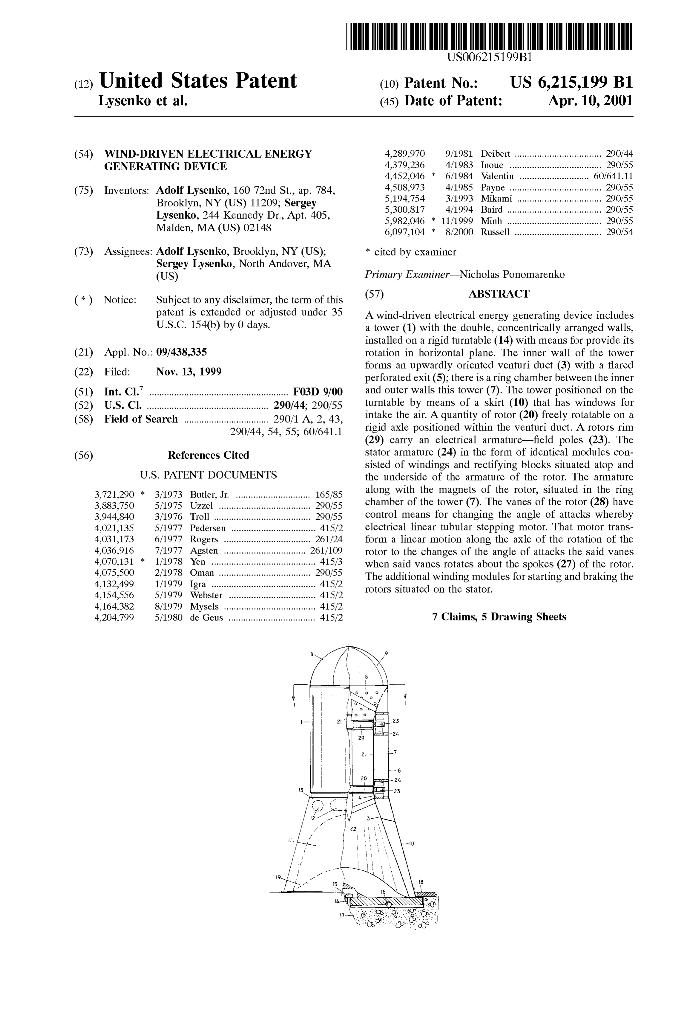
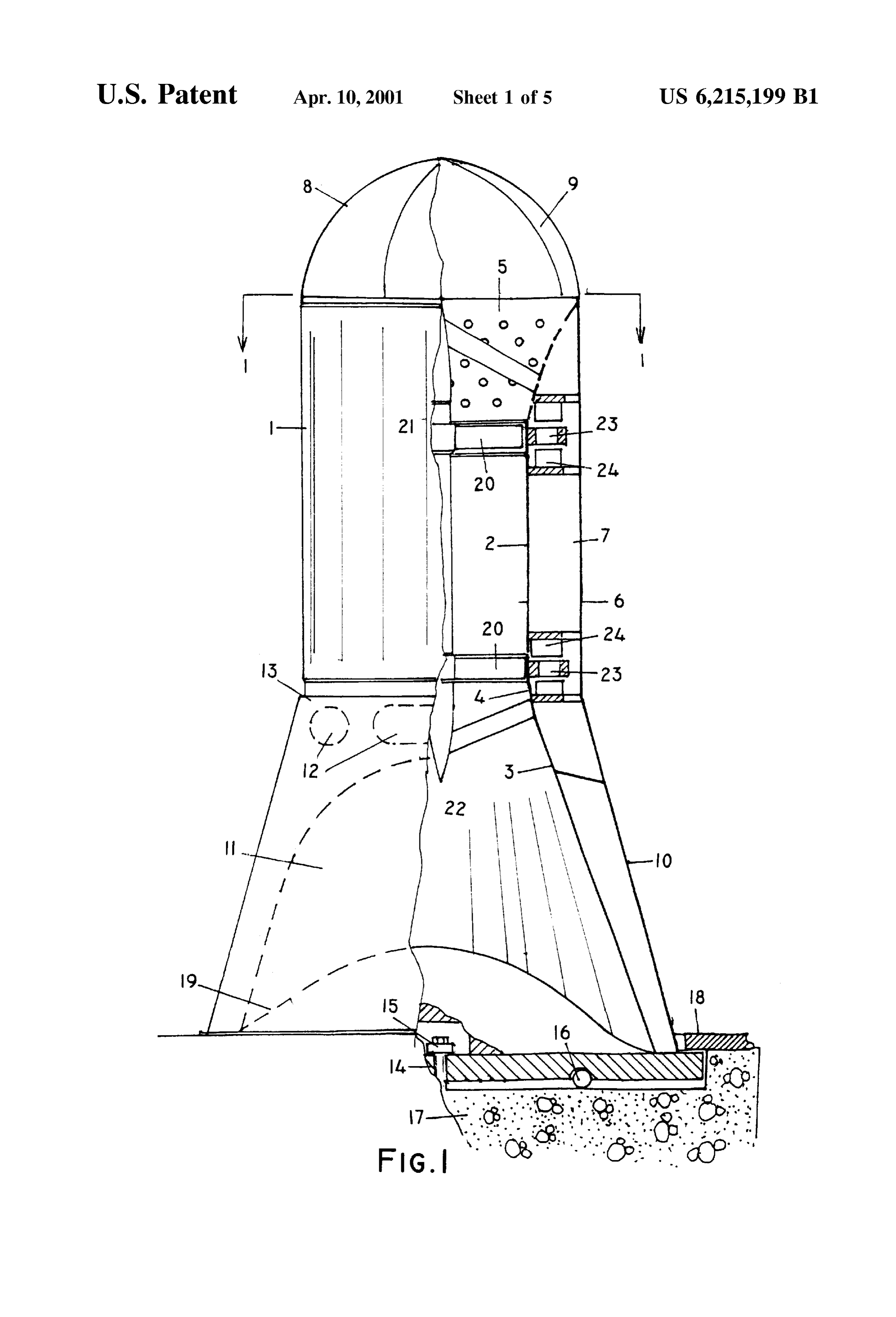
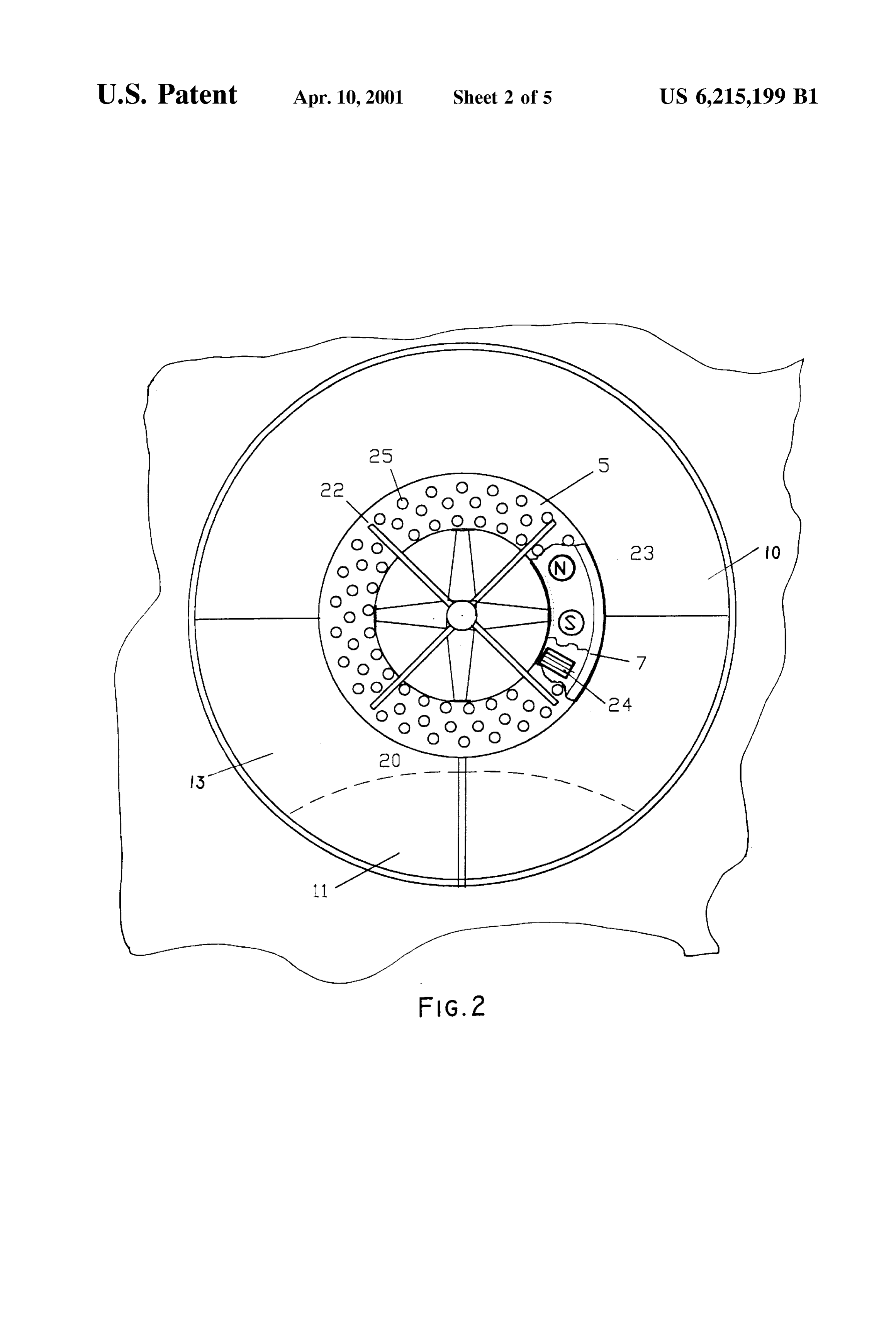
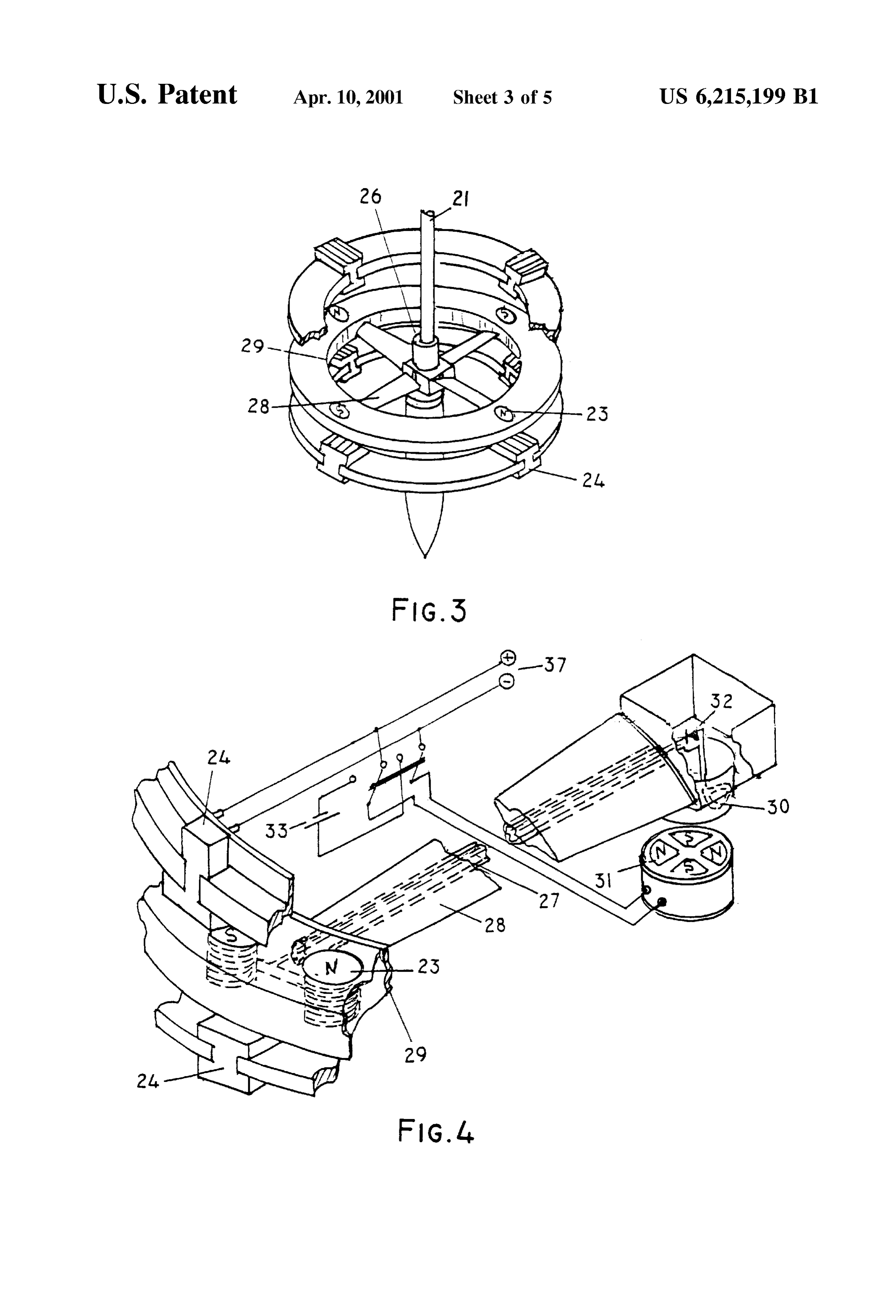
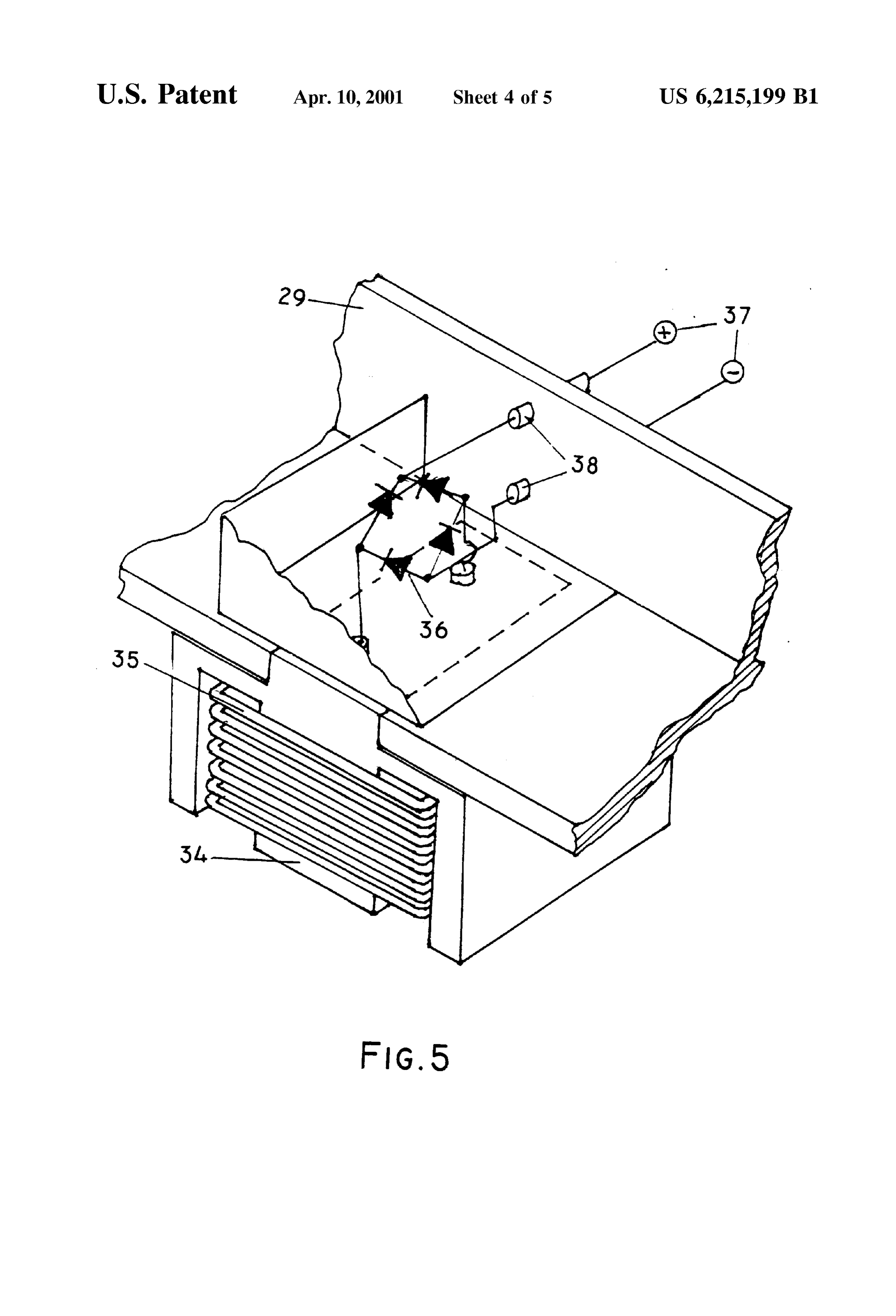
DRAWING FIGURES the double, concentrically arranged walls installed on a rigid FIG. 1 is a partial sectional view of a wind-driven turntable with means for provide its rotation in horizontal plane. The inner wall of the tower forms an upwardly electrical energy device. 15 oriented venturi duct with a flared perforated exit. There is FIG. 2 is a plan Sectional view of the device taken along a ring chamber between the inner and Outer walls, a quantity line 1-1 of FIG. 1. of rotors freely rotate on a rigid axle positioned within the FIG. 3 is a perspective exploded view of the rotor with the Venturi duct. There is an electrical armature on the outer part field poles and Static armature of the rims of the rotors. Those armature and Stator windings FIG. 4 is a perspective view of an electrical connection of in the form of identical modules atop and the underside of the generator the armature of the rotor situated in the ring chamber of the FIG. 5 is a perspective view of the modular element of the tower. The armature and windings are cooled by the air that Static armature. is passing past, then this air go further to plurality of the air duct that are situated in the upper part of the Shroud
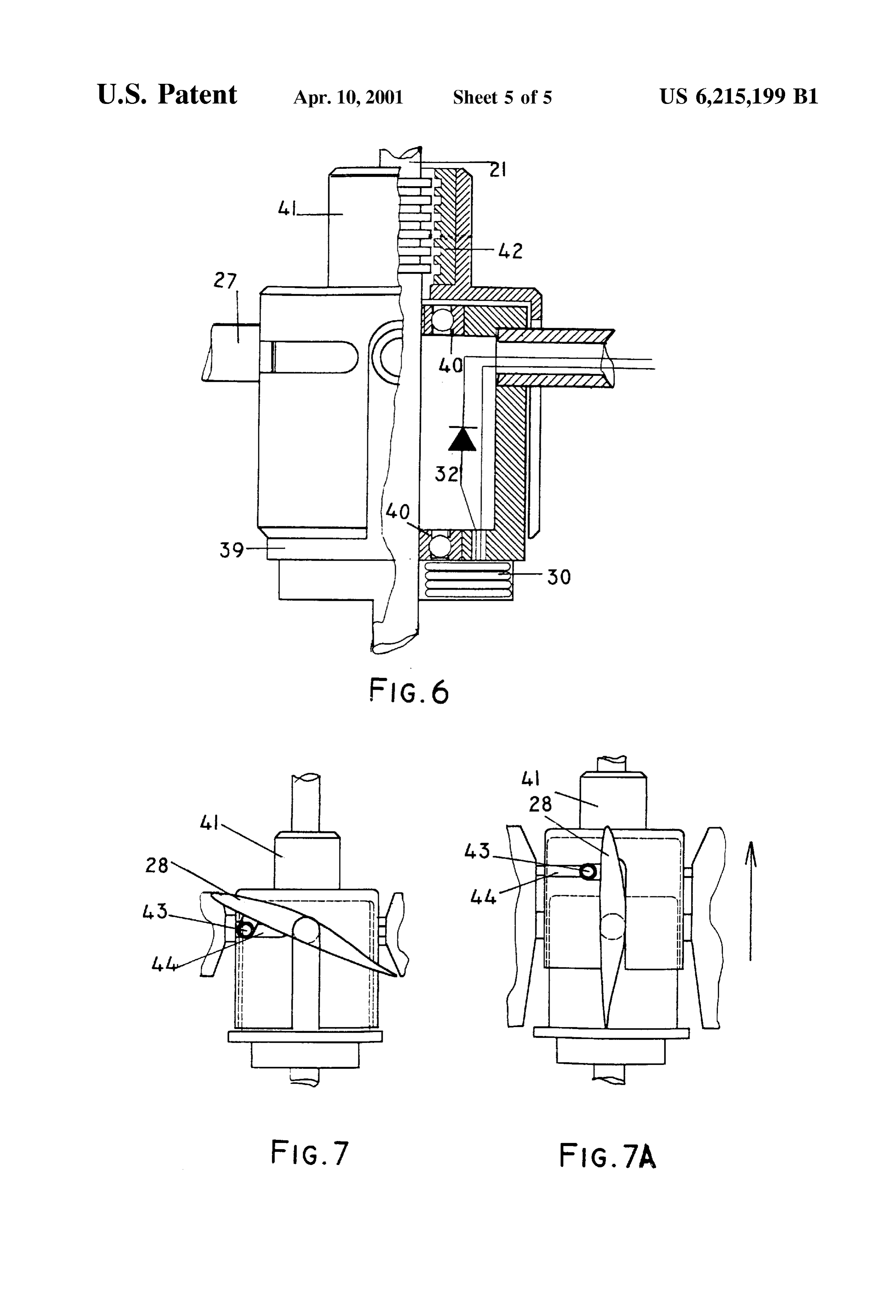
FIG. 6 is a partial sectional view of the hub of the rotor. 25 (diffuser) and preventing the premature air separation along FIG. 7 is a view of the pitch control mechanism and the the diffuser and therefore increasing the its effectiveness. coupling of the Vanes of the or to the pitch control mecha nism. DESCRIPTION FIGS 1-7 REFERENCE NUMERALS IN DRAWINGS Refer now to FIGS. 1-2, which are a partial sectional view of a preferred embodiment of the invention and a plan
Sectional view of the device. The energy-producing device comprises of a vertical cylindrical tower 1 with the double 1. cylindrical tower concentrically arranged walls. The inner wall 2 of this tower
forms an upwardly oriented Venturi duct 3 with a lengthened 4 intake narrowing end neck. The upper part of that duct makes up a flared exit 5 5 flared perforated exit with the perforated walls, the most diameter that exit equal 6 outer cylindrical wall to the diameter of the outer cylindrical wall 6. A cylindrical
8 upper cap ring chamber 7 forms between the inner 2 and outer walls 6.
The uppermost part of the tower has a cap 8. This cap turns
bottom skirt bottom window the air emerging from the duct windward. The cap has a gate
9 for shielding the inner parts of the device in the bad
weather.
urntable axle of turntable
An expanding to bottom skirt 10 with a window 11 16 bearings of the turntable 45 supports the tower 1. Through the window 11 an ambient air 17 aSe may be drawn into the inner duct 3, and through the 18 plate windows 12 an ambient air may be drawn into the ring
arge neck rotor cylindrical chamber 7. The windows 11 and 12 have a 21 rotors axis of rotation common gate 13. The skirt 10 is mounted on a rigid turntable 22 Struts 50 14 that is liable to rotate about vertical axis 15, and it has a 23 field poles means (not shown) for the rotating and fixing it in Such a
stator windings orifices way as to keep the windows 11 and 12 windward.
26 hub of the rotor The turntable 14 bears up against the bearings 16 that are 27 spokes rested on a hard base 17,and edges of the turntable are 28 WaleS 55 located under a brim of a static circular plate 18 that is stiffly
3O windings of the satellite generator tied with the base. This provides a way of withstands with 31 poles of the satellite generator a big loading that attacks on the generator tower 1 in time of 32 rectifier the Storms.
33 batteries The inner wall 4 of the Supporting skirt 10 and the duct 3
35 coil 60 comprise a unified channel having at its lower end a large 36 rectifying block diameter neck 19. A central part of the channel is a narrow 37 electrical buses neck 3 with constant diameter in which a plurality of rotors 38 plugs 20 are situated. The rotors freely rotate about an axis 21 39 body of the hub extending vertically in the duct and fixed in by the Struts 22. 40 bearings of the rotor 41 sleeve of the hub 65 There are the field poles 23 on the outer rim of the rotors. 42 rotor of the stepper Stator windings 24 are fitted on the ring Structural elements that were made from nonmagnetic material. The Stator
Page 9
S 6 windings as well as the field poles are situated in the ring a short pin 43. The pins of the all vanes 43 enter into the chamber 7. The outlet 5 with an uppermost opening repre grooves 44 in the sleeve of the hub 41. When the sleeve Sents a perforated diffuser that allows the air exiting the moving linearly pins 43 rotate the Vanes about the spokes of rotors 20 to return to the atmosphere. The upward flow of air the rotor.
in the venturi duct 3 rotates the rotors 20 to provide torque In the center of the turntable of this device installed a capable of creating a necessary Voltage. The air entering the streamlined elevation 45 for an organized flow of the air windows 12 and passing by Stator windings in the chamber immediately on the intake of the duct. 7 and cooling it. Thereupon the air passes through the The foregoing description of the preferred embodiment of plurality of orifices 25 and ejected to the main Stream. the invention has been presented for the purposes of illus FIGS. 3-4 is a perspective exploded view of a rotor with tration and description. It is not intended to be exhaustive or the field poles and the Static armature of the generator and to limit the invention to the precise form disclosed. Many a perspective view of the electrical connections of the modifications and variations are possible in light of the generator. Its show the internal component of the energy above teaching. It is intended that the Scope of the invention producing part of the present invention including the con be limited not by this detailed description, but rather by the Struction of the rotors with the constituents of an electrical 15 claim appended hereto.
generator. The rotor powered by a wind fulfills the role of a rotor of the generator. It is consistent of a hub 26, Spokes 27, OPERATION FIGS 1-7 the vanes 28, and rim 29. The spokes of the rotor are the axes of rotation for the Vanes under the changing the output of the In accordance with the present invention, wind-driven generator. An even number of the field poles 23 is situated electrical energy generating device is mounted in any perimetrically on the outer part of the rim of the rotor. A desired location on the ground, preferably on places rising Source of the energy for the field poles is a Satellite generator above the adjacent lowlands and where are no obstructions. that forms from flat windings 30 and the electromagnets or The tower 1(FIGS. 1-2) is positioned in such a way that permanent magnets 31. The flat windings 30 are situated on windows 11 and 12 of the skirt 10 are situated in the the bottom butt of the hub of the rotor. The electrical stream 25 direction of the wind. With the gates 9 and 13 open the wind induced in the winding 30 as the rotor rotates enters to a enters the duct 3 and ring chamber 7. Velocity of the air is rectifier 32 and further arrives to field poles accelerated in the Venturi duct, whereby, when it contacts the electromagnets 23. Starting of the wind generator is per rotors it are rotated at increased Velocity relative to the formed by the use of storage batteries 33. The electromag Velocity of an unducted rotors of the same dimensions in the nets are fed from the output of the generator when operating Same wind.
at nominal rating. The air entering in chamber 7 travels all the way from the A second variant of the rotor is the rotor with the lower part of the tower to the top. AS this air passed by the permanent magnets 23. In this case the main generator has stationary field structures-modules 24, it cooled them and no need of a Satellite generator. 35 then goes to exit in diffuser part of the duct through the
There are also the Static ring armature Structures, which plurality of annularly arrayed, axially spaced orifices 25. Situated atop and underSide the plane of rotation of the rotor. The outlets of all the air orifices are disposed in the form These armature Structures made in the form of Separate of the channels in outwardly flared outlet 5. These air modules Surround the rotor as well perimetrically. A Station channels inject a flow of air of high kinetic energy from the ary field structure comprises an even number of the discrete 40 airstream to the boundary layer of the main airstream within modules 24 (FIGS. 3-5). Every that module comprises of the diffuser section of the duct, and thereby reduce or the core 34, a plurality of coil 35, and a rectifying block 36. prevent Separation, which could cause a Sharp lowering of A direct current output inducing in the every module 24 is rotors performance.
carried to the positive and negative electrical buses 38 by a AS the rotor begins its rotation an EMF is generated in plug 37 this enables possibility Simple replacing of the faulty 45 moving windings of the satellite generator 30 (FIGS.3-5). In blockS. Consequently, the every rotor has a Stationary field this time it must use a storage battery as Source of energy. Structure that comprises of a two plurality of the modules 24 Thereafter electrical Stream goes through the rectifier 32 to that are circularity positioned atop and underSide of the field the field poles of the rotor 23. This revolving armature 23 in structures of the rotors. The windings outlined above can be turn induced an EMF in the static armature modules 24. used for an electrical Starting and braking of the rotors. The 50 Upon leaving the rectifying blockS 36 direct current arrives moving armature Structures and the Static modules are to electrical buses 38. The field poles of the satellite gen situated between the inner and outer walls of the tower 1. erator (magnets) 31 are energized from the buses 38 after Referring now to FIG. 6 it is observed that the hub of the achieving Some output.
rotor comprises of a body 39 with the bearings 40 and the The electrical output from this wind-driven direct current sleeve of the hub 41. That sleeve can move along the axis of 55 electrical generator may be used as direct electrical power, rotation of the rotor 21. The upper part of the moving sleeve it may be converted to alternating current, or it may be used represents a "rotor of the tubular linear Stepper motor as a Source of energy to be converted into other forms for (stepper) 42. The adjacent part of the Stationary axis is a storage. When the rotor with a field poles rotates between the “stator' of this motor. A movement of the sleeve is created Static armature Voltage are induced by commands from some drive circuit (not shown). The 60 Varying the pitch of the vanes 28 (FIGS.6-7) effects the windings of the satellite generator 30 reside in the bottom of changing of Speed of rotations of the rotor and, the hub. The rectifiers of the satellite generator 32 reside consequently, the output of the generator. AS Shown in inside of the hub. FIG.5, when moving the hub sleeve 41 along the axle of A mechanism of varying of the pitch of the Vanes had rotation of the rotor the groove 44 cause moving the pin 43 shown by FIG. 7. The spokes of the rotor 27 are the axis of 65 that is situated on the root section of the vane 28. AS this take rotation for the vanes 28. The output the rotor depends on the a place, the Vane turns up or down depending on of the angle of attacks of the Vanes. The root of the every vane has direction of that movement. The hub sleeve 41 is a moving
Page 10
part of a linear tubular Stepping motor and therefore pow a quantity of rotors freely rotatable on a rigid axle ering the drive circuit of that motor we can changed a angles positioned within Said Venturi duct, every of the rotor of pitch the Vanes. The range of the angles of pitch may be comprising of central hub, the plurality of spokes, on varied from 0 to 90 degrees. each said Spoke is mounted a vane in Such a manner CONCLUSION, RAMIFICATION, AND SCOPE that spoke is an axle of rotation for Said Vane, Said Accordingly, the reader will see that the wind-driven spokes angularily-spaced, radially-extending connect electrical energy-generating device of this invention pre ing the central hub and a circular rim carrying the Sents a comparatively simple facility for transforming electrical armature, Source of energy for that armature energy of the wind to electrical energy. This electrical is a satellite generator situated on butt of the hub of the energy generating device has a low cost of the construction rotor; Said Vanes are situated in the Venturi duct, and and the maintenance because is of Simple design, it and may Said armature is situated in the Said cylindrical ring be build from a cheap materials. It has a few moving parts chamber of the tower; a Stationary Stator winding or and has not moving electrical contacts. These factors have a field structures that comprises of an even number of favorable impact on a price of the generated energy. In addition, the design of this wind generator provides a 15 discrete modules, each of the module comprises of the possibility of working in a big range of a speed of the wind. core, a plurality of coils, and a rectifying block, Said AS a rotor of the generator are shielded from a direct modules circularly positioned atop and the underSide of action of the wind they do not experienced fatigue Stresses the field structures of the rotor in Said cylindrical ring from the gust of the wind, and, therefore, they have a high chamber, and the electrical direct current output from reliability. That reduces the structural requirements of the every Said blocks are connected with common buses Supporting tower and the generator System. The coils of the the plugs, a base comprising of a rigid turntable with winding cooled by the passing air, then this air go further to means for provide its rotation in horizontal plane about plurality of the air ducts that are situated in the upper part of the vertical axis and fix it in the necessary position, and the duct that prevent premature air Separation along the with means for opposing the big wind loads exerting on diffuser of the shroud and therefore increasing the its effec 25 Said tower, and a narrowing up skirt positioned on Said tiveness. The Special convention of this generator is that turntable with a set of a windows in the bottom part of there are not moving electrical contacts in all design the Side Surface of Said skirt, Said windows are posi The generator has the means for controlling the rotational tioned in Such a way that air is arrived via Said windows Speed of the rotors wherein this means includes means for to the Venturi duct and ring cylindrical chamber of Said controlling the pitch of the rotor Vanes, and has the means tOWer.
for Starting and braking rotor by electrical means. AS 2. The wind-driven electrical energy-generating device opposed to a current design of the wind generators our of claim 1 wherein Said circular rim of Said rotor comprises generator have low level of the acoustic noise, and its vanes the permanent magnets.
do not cause electromagnetic interference and worsening 3. The wind-driven electrical energy-generating device receiving the radio and TV programs. By and large this 35 of claim 1 wherein including control means for changing the device do not impact on the environment. The distinctive angle of attacks of the Vanes of the rotors whereby electrical characteristics of that design that in the course of operation linear tubular Stepping motor through the transformation of will be manifested itself an effect of the chimney. What this the linear motions of the motor along the axis of the rotation means is bigger design will be more effective. of Said rotor to the changes of the angle of attackS Said Vanes Although the description above contains many specifities, 40 when said Vanes rotates about Said spokes of the rotor. these should not be construed as limiting the Scope of the 4. The wind-driven electrical energy generating device of invention but as merely providing illustrations of Some of claim 1 further comprising the additional Stator windings for the presently preferred embodiments of these inventions. Starting and braking Said rotors whereby creating a variable For example, depending on the weather conditions of the Site and constant magnetic fields.
the turntable of the tower can be made as a Static 45 5. The wind-driven electrical energy generating device of construction, or the tower need not be vertical, etc. claim 1 further comprising in upper part of the tower a Thus the scope of the invention should be determined by Special hat to ensure a turn of the exiting air windward, the appended claim and their legal equivalents, rather than through a Same angle.
by the examples given. 6. The wind-driven electrical energy generating device of What is claimed is: 50 claim 1 wherein in the bottom of the central part of said skirt 1. A wind-driven electrical energy generating device on the turntable is situated a streamlined elevation to mini comprising a tower with the double, concentrically-arranged mize aerodynamic losses of the air at the intake part of Said walls, the inner wall Said tower forms an upwardly oriented Venturi duct.
Venturi duct with an intake narrowing end Situated in the 55 7. The electrical energy generating device of claim 2 bottom of the tower and an flared perforated exit end situated wherein on the intake windows on Said skirt and the exit in upper part of the tower with the most diameter Said exit window of Said cup are installed gates with means for equal to the diameter of the outer cylindrical wall, therewith opening and closing Said windows.
a cylindrical ring chamber forms between the inner and outer walls,
Provenance
- Collection
- Cited prior art
- Original PDF
- patentimages.storage.googleapis.com →
- Filed
- 1999-11-13
- Pages
- 10
- Method
- pdftotext (the PDF's own text layer) + pdftoppm 300dpi page scans
- Source
- Google Patents bibliographic record
- Granted
- 2001-04-10
- Inventors
- Adolf Lysenko; Sergey Lysenko
- Transcribed from
- patentimages.storage.googleapis.com →