patent · US4720640
Fluid powered electrical generator
19 January 1988
Page 1 — bibliographic record
United States Patent (19) 11 Patent Number: 4,720,640 Anderson et al. (45) Date of Patent: Jan. 19, 1988 54 FLUD POWERED ELECTRICAL 4,261,171 4/1981 Atencio ............................ 290/53 X GENERATOR 4,275,989 6/1981 Atencio ....... ... 415/129 4,276,482 6/1981 Crockett ............................... 290/52 75 Inventors: Bjorn M. S. Anderson, Woodside; 4,279,539 7/1981 Atencio ............................ 290/53 X Reinhold H. Ziegler, Berkeley, both 4,309,621 1/1982 Litz ....................................... 290/52 of Calif. 4,324,985 4/1982 Oman. ... 41.5/2 AX 4,326,819 4/1982 Atencio ............................ 290/53 X 73 Assignee: TurboStar, Inc., Menlo Park, Calif. 4,352,989 10/1982 Atencio ................................. 290/53 (21) Appl. No.: 779,227 4,367,413 1/1983 Nair ....................................... 290/52 22 Filed: Sep. 23, 1985 Primary Examiner-Patrick R. Salce 51 Int. Cl'.............................................. FO3B 13/10 Assistant Examiner-Emanuel Todd Voeltz Attorney, Agent, or Firm-Limbach, Limbach & Sutton (52) U.S. C. ........................................ 290/43; 290/54;
415/2 R; 415/4; 416/9; 416/93 R; 416/179 (57) ABSTRACT (58) Field of Search .................................... 290/42-44, A fluid powered electrical generator having an impel 290/53-55; 415/2-4, 146, 147, DIG. 1; 416/9, lor-rotor rotatively mounted on a central support struc 93 R, 179-184; 310/68 R, 68 B, 68 D, 87, 154, ture. A toroidal outer support structure surrounds the 156, 254, 179-181, 185,268 impellor-rotor, with the impellor-rotor including a plu 56) References Cited rality of circumferentially spaced-apart fluid dynamic
together by a rotor rings which is coaxial with respect 984,599 2/1911 Pichault.............................. 4.5/2 A to the outer support structure. The central support 1,783,669 12/1930. Oliver ..... ... 41.5/2 A structure is supported within the outer support struc 1,944,239 i/1934 Honnef.................................. 290/55 2,517,135 8/1950 Rudisill ... ..., 416/9X ture by stanchions or the like so as to permit a fluid 2,563,279 8/1951 Rushing. ... 290/55 X stream to flow therebetween past the fluid dynamic 2,970,238 1/1961 Swiggett ..... ... 310/268 blades. A peripheral electrical generator having a rotor 3,624,439 11/1971 Tokutomi.......is seagooooooooooooooo- 310/154 element secured to the rotor ring and a stator element 4,021,135 5/1977 Pederson et al. ... 415/2 A secured to the outer support structure produces electri 4,075,500 2/1978 Oman et al. ........................... 290/55 cal energy as the impellor-rotor is driven by the fluid 4,078,388 3/1978 Atencio ...... ... 290/53 X 4,118,636 10/1978 Christian ........................... 290/54 X stream.
4,204,799 5/1980 de Geus .......................... 415/3 AX 63 Claims, 35 Drawing Figures
Page 2
Drawing sheet — no readable text.
Page 3
Drawing sheet — no readable text.
Page 4
Drawing sheet — no readable text.
Page 5
Drawing sheet — no readable text.
Page 6
Drawing sheet — no readable text.
Page 7
Drawing sheet — no readable text.
Page 8
Drawing sheet — no readable text.
Page 9
Drawing sheet — no readable text.
Page 10
Drawing sheet — no readable text.
Page 11
Finally, conventional wind turbines generate power
FLUID POWERED ELECTRICAL GENERATOR through a gearbox and conventional generator. Al though these generators are commonly available, they
DESCRIPTION represent a one hundred year old technology that has not incorporated recent technological breakthroughs in
The present invention relates in general to an axial 5 material flow fluid energy conversion method and apparatus and These science, power control and aerodynamics. generators, while compact, are heavy because of more particularly to an axial flow fluid turbine genera the massive laminated tor method and apparatus. iron core and copper windings. BACKGROUND TO THE INVENTION PRIOR ART
It has long been thought that substantial performance
One of the oldest methods of extracting energy from advantages fluids in motion is by means of bladed rotating machines diffuser on acould fluid be realized by the use of a shroud and turbine (see "A Preliminary Report such as, for example, windmills exposed to the wind and on Design and Performance of Ducted Windmills' G. hydro impellors powered by the fluid reaction of mov 15 N. M. Lilley and W. J. Rainbird, The British Electrical ing water. While these devices have been successfully and Allied Industries Research Association, employed for many hundreds of years, there still remain ain Technical Report C/T119, 1957). PriorGreat work Brit
major unresolved technical problems in the design of Grumman Aerospace Corporation as described in U.S. conventional wind turbines which make them problem Pat. No. 4,075,500 indicated that diffuser augmented atic for small and large scale energy production.
These technical problems fall into basically three 20 turbines could produce at least twice the power output of conventional turbines.
categories: fluid dynamics, dynamic stress, and electri Other prior art patents showing shrouded wind tur cal conversion.
The fluid dynamic difficulties can best be appreciated 2,517,135;
by the Betz theory which expresses limitation on poten 25 closes and 2,563,279. U.S. Pat. No. 1,944,239 dis tial energy conversion and which is described in Tech ter-rotating bladewind an electric dynamo consisting of two coun wheels which can include a single nical Note #75 "Meteorological Aspects of Utilization armature wheel connected of Wind as an Energy Source,” World Meteorological blades to cooperate with fieldtomagnets the partial span of the carried by a rigid
Organization 1981. The column of air (wind) impelling bracket.
upon the windmillsblades is slowed and its boundary is 30 Ducted turbines have been shown to be the most an expanding envelope where streamlines meet turbu effective way to augment the power output from con lence behind the rotor. Attempts to shroud the envelope to utilize the lower pressure behind the blades as a fluid ventional date no turbines but also the most expensive way. To practical, economical wind turbine has been dynamic advantage have been suggested in U.S. Pat. produced.
No. 4,075,500 as well as others. To date no practical 35 Various coil and magnet structures are disclosed in cost effective method exists for fabricating ducted U.S. Pat. Nos. 1944,239, 4,088,352, 4,276,482, 4,309,621 shrouds, much less balance them on support structures. and 4,367,413.
Mechanical stresses induced on the blading and sup port structure present further limitations especially for OBJECTS OF THE PRESENT INVENTION large windmills. On the supporting structure the axial 40 An object of the present invention is to provide an stress representing the force which tends to overturn energy conversion method and apparatus to avoid the the windmill, or the thrust on the bearing, must be kept fluid dynamics, structural dynamics and electrical prob within limits at all wind speeds. To accomplish these lems of conventional fluid turbines. results and to generate sufficient and efficient power, A particular object of the present invention is to large diameter blades with built-in governors for adjust 45 provide a shrouded fluid turbine structure with im ing the pitch angles of the blades have been utilized. proved efficiency and mechanical stability. These mechanisms proposed to date make the blades A further object of the present invention is to provide fragile and costly. a monolithic rotor that functions simultaneously as a Furthermore, large diameter blades, such as over 100 fluid impellor and electromagnetic rotor thereby saving feet in length, present significant dynamic stress prob 50 on construction, safety and maintenance, while elimi lems. The increased blade length of larger rotors re nating a transmission gearbox.
quires greatly increased blade stiffness and reduced It is a further object of the present invention to pro weight in order to insure that critical vibrational fre vide economical methods for constructing aero and quencies of the blade remain sufficiently outside the hydrodynamic shrouds and thereby produce a machine excitation frequencies associated with routine operation 55 that can take advantage of low speed fluid flows. so that the blades do not become unstable. A combina It is still a further object of the present invention to tion of gravitational force and torque force on each provide a modular constructed ducted shroud with blade element functions to cyclically stress the blade boundary layer control that is simultaneously flexible element as it rotates in a rising direction and then a and adapted to a variety of flow streams (wind or wa failing direction. Long blades supported at their roots ter).
and under the influence of the aforementioned oscillat It is still another object of the present invention to ing forces are subjected to an increasingly severe and provide unique methods and apparatus for venting fluid complex system of dynamic instabilities. It is difficult from the fluid stream in and through the shroud and and expensive to safeguard against such instabilities. turbocage of the turbine in accordance with the present Blade stiffness to weight ratio improvements and ad 65 invention.
vanced design methods can help but there is always a It is still a further additional object of the present practical maximum to the size of blades being employed invention to provide a mounting mechanism that treats by wind turbines. the rotor as a gyroscope and to utilize the precession
Page 12
which occurs when external torques are exerted on a ripheral ring of the impellor-rotor and an inductive rotating gyroscope to position the rotor. coupler is provided for removing electrical power from It is still a further object of this invention to incorpo the armature.
rate airfoils as stabilizing elevators which can tilt the In accordance with still another aspect of the present axis of the unit out of the fluid flow stream when over invention the outer support structure of the fluid turbine speed occurs. incorporates a diffuser or shroud formed as a toroid It is still yet a further object of the present invention having a fluid dynamic cross-section. to produce electrical power over a wide range of drive In accordance with still another aspect of the present fluid velocities. invention the diffuser or shroud of the last aforemen It is an additional object of the present invention to 10 tioned aspect incorporates an outer catenoid surface. provide a rotor armature having a low moment of iner In accordance with still another aspect of the present tia which is responsive to rapid changes in drive fluid invention the outer surface of the diffuser shroud can be velocity.
It is still an additional object of the present invention outer surface specifically other shapes and a including a truncated conical parabaloid outer surface.
to provide a fluid driven electrical generator which 15 In accordance with still another aspect of the present does not require the use of friction producing and neces invention the diffuser shroud includes means for pas sary to replace brushes and slip rings. sage of fluid therethrough, either for discharge along It is yet still an additional object of the present inven the inside surface of the diffuser shroud or for passage tion to alternatively provide a fluid driven generator way across the space between the outer and inner sup armature which acts as a flywheel for temporarily stor 20 port structures for discharge at the central support ing energy. Structure.
Broadly stated the present invention to be described In accordance with still another aspect of the present in greater detail below is directed to an axial flow fluid invention at least the inner surface of the diffuser shroud turbine generator apparatus incorporating a central support structure, a hollow outer support structure 25 isflow formed of a flexible material for flexure with fluid through the apparatus.
surrounding and connected to the central support struce ture and adapted to pass a stream of fluid between such inventionIn accordance with still another aspect of the present support structures and an impellor-rotor rotatively cludes at least the diffuser shroud of the fluid turbine in mounted on the central support structure and including certain surfaces made of flexible material and : a plurality of circumferentially spaced fluid dynamic 30 shroud. means for controlling the pressure inside the blades for transferring energy from a stream of fluid and a ring connecting the radial outward ends of the blades. These and other aspects, features and advantages of A feature and advantage of the present invention is the present invention will be become more apparent that electrical generating structures can be provided on upon a perusal of the following specification taken in the ring.on the impellor-rotor and a surrounding stator 35 conjunction with the accompanying wherein similar portion of the outer support structure. characters of reference refer to similar parts in each of In accordance with another aspect of the present the several views.
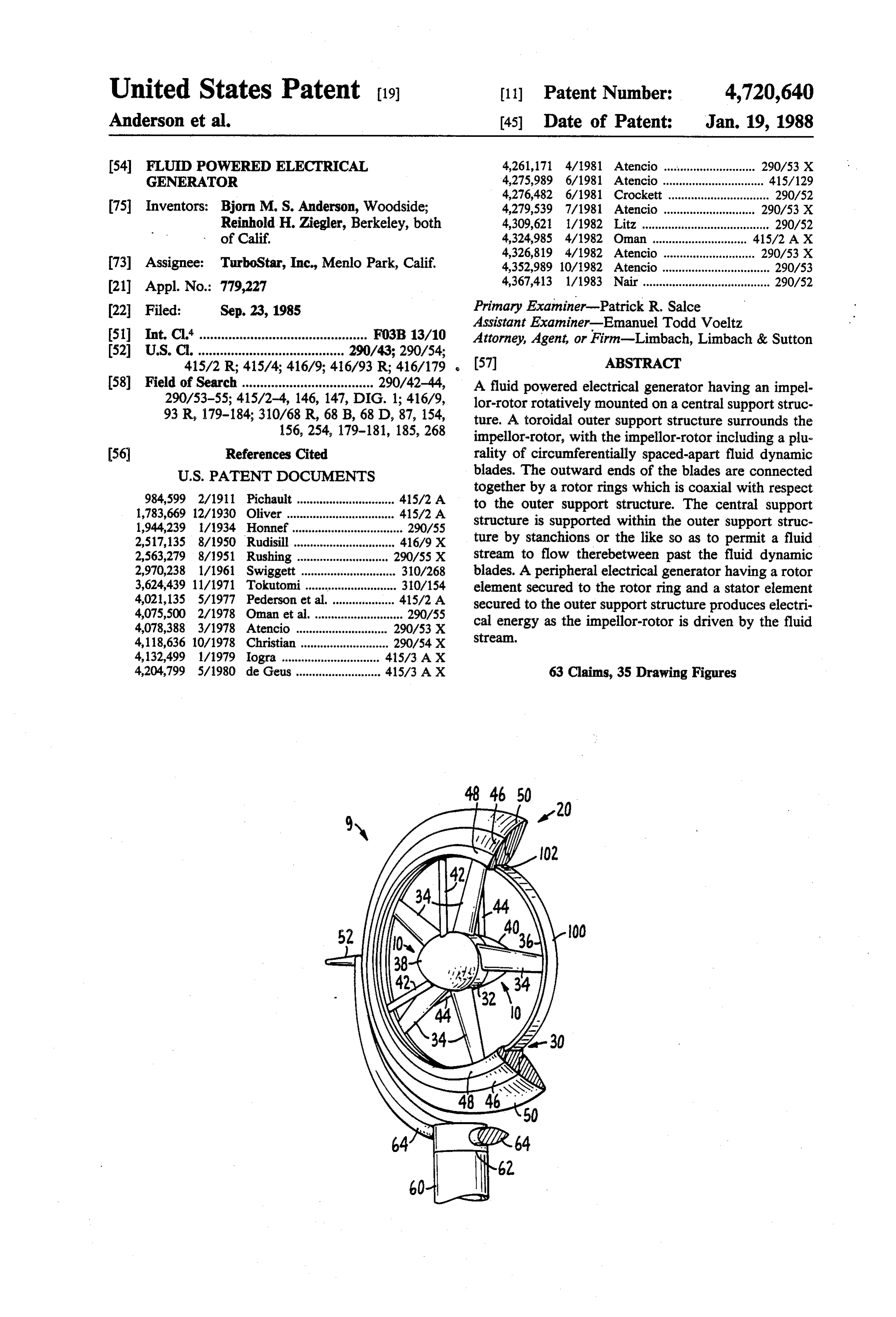
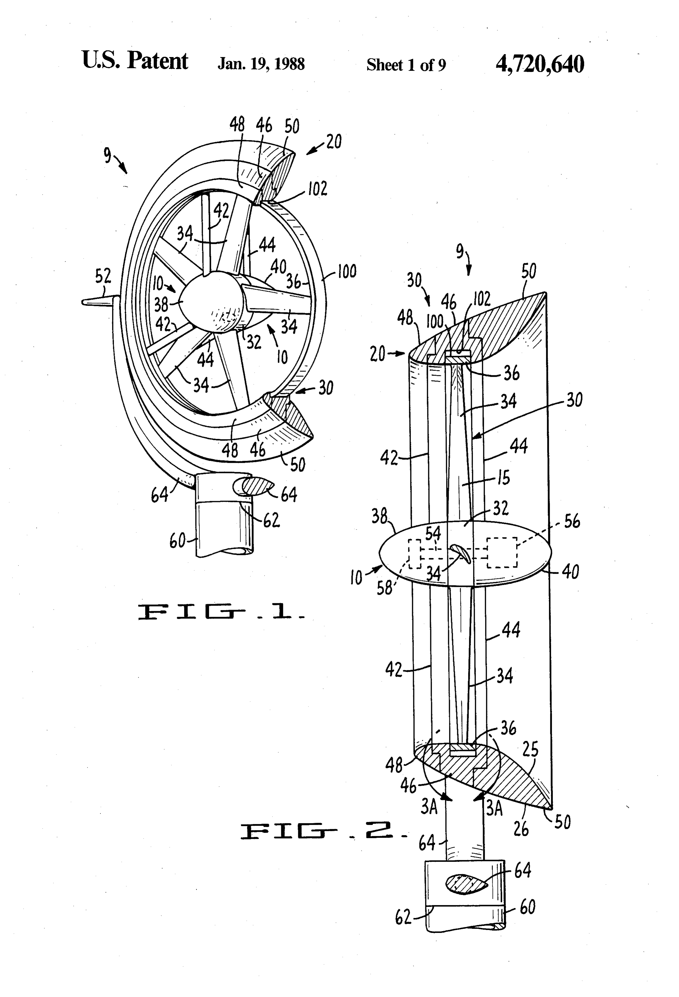
invention an armature comprised of a number of differ DESCRIPTION OF THE DRAWINGS ent coil configurations can be provided on the periph -eral ring of the impellor-rotor for interaction with mag FIG. 1 is a perspective view, partially broken away, netic circuits located on a surrounding, closely spaced illustrating a preferred embodiment of the wind turbine stator portion of the outer support structure. of the subject invention.
In accordance with another aspect of the present FIG. 2 is an enlarged elevational view, partially bro invention different magnetic circuit configurations can ken away, further illustrating the embodiment of FIG. be provided on the ring periphery of the impellor-rotor 45 1.
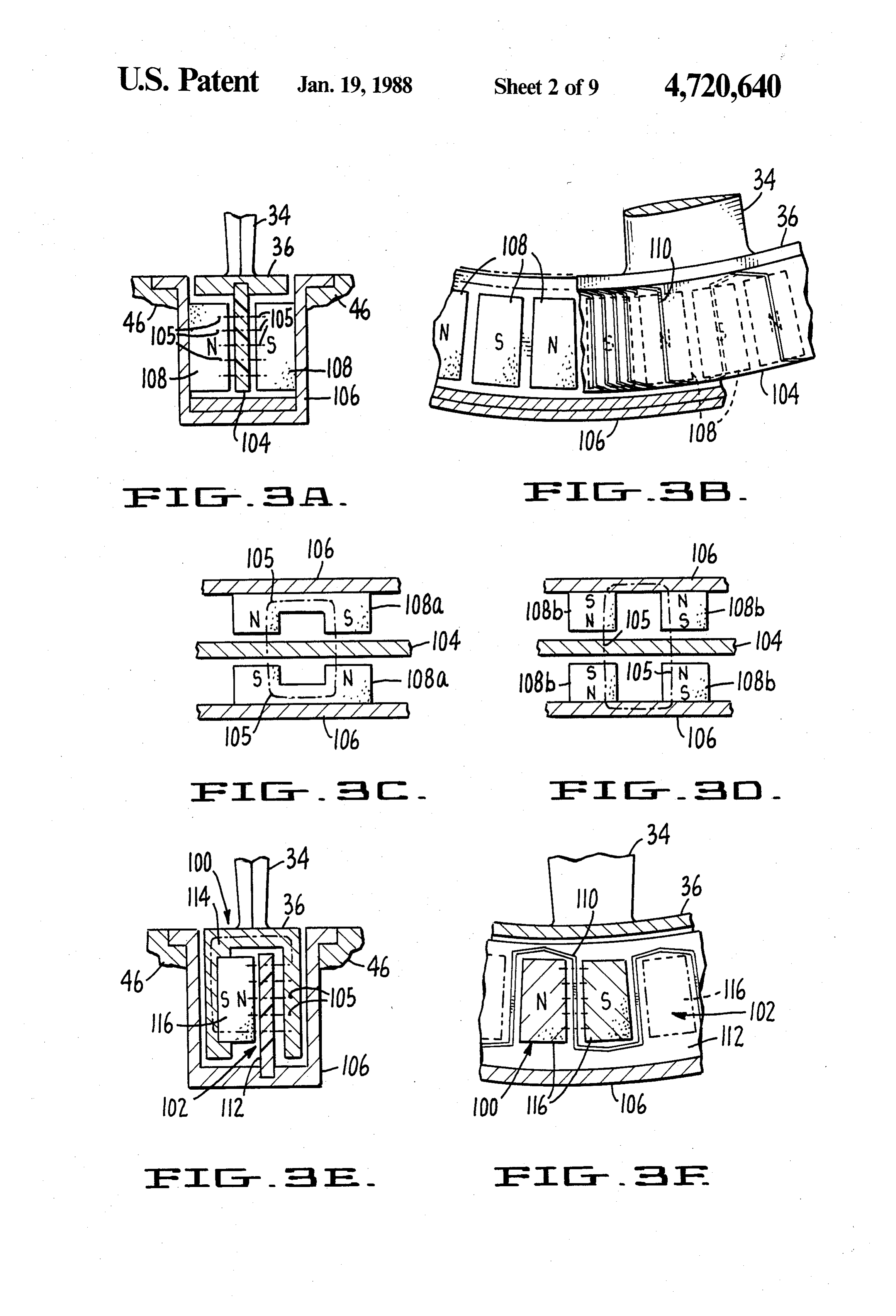
for cooperation with coil circuits mounted on the FIG. 3A is an enlarged cross-sectional front view closely spaced stator portion of the outer support struc taken along section line A-A of the FIG. 2 structure ture. showing details of one embodiment of an armature/- In accordance with another aspect of the present magnet configuration having a rotating planer armature invention, a monolithic armature can be provided hav 50 and fixed field magnets.
ing an insulating substrate and individual coils printed FIG. 3B is an enlarged cross-sectional side view of on the substrate. the armature/magnet configuration of FIG. 3A. In accordance with a further aspect of the present FIG. 3C is an enlarged cross-sectional plan view of a invention, an armature can be provided having no sup first embodiment of the armature/magnet configuration porting substrate wherein the individual coils are chem 55 of FIG. 3A ically milled from a conductive material such as copper, FIG. 3D is an enlarged cross-sectional plan view of silver or the like. an alternative embodiment of the armature/magnet In accordance with another aspect of the present configuration of FIG. 3A.
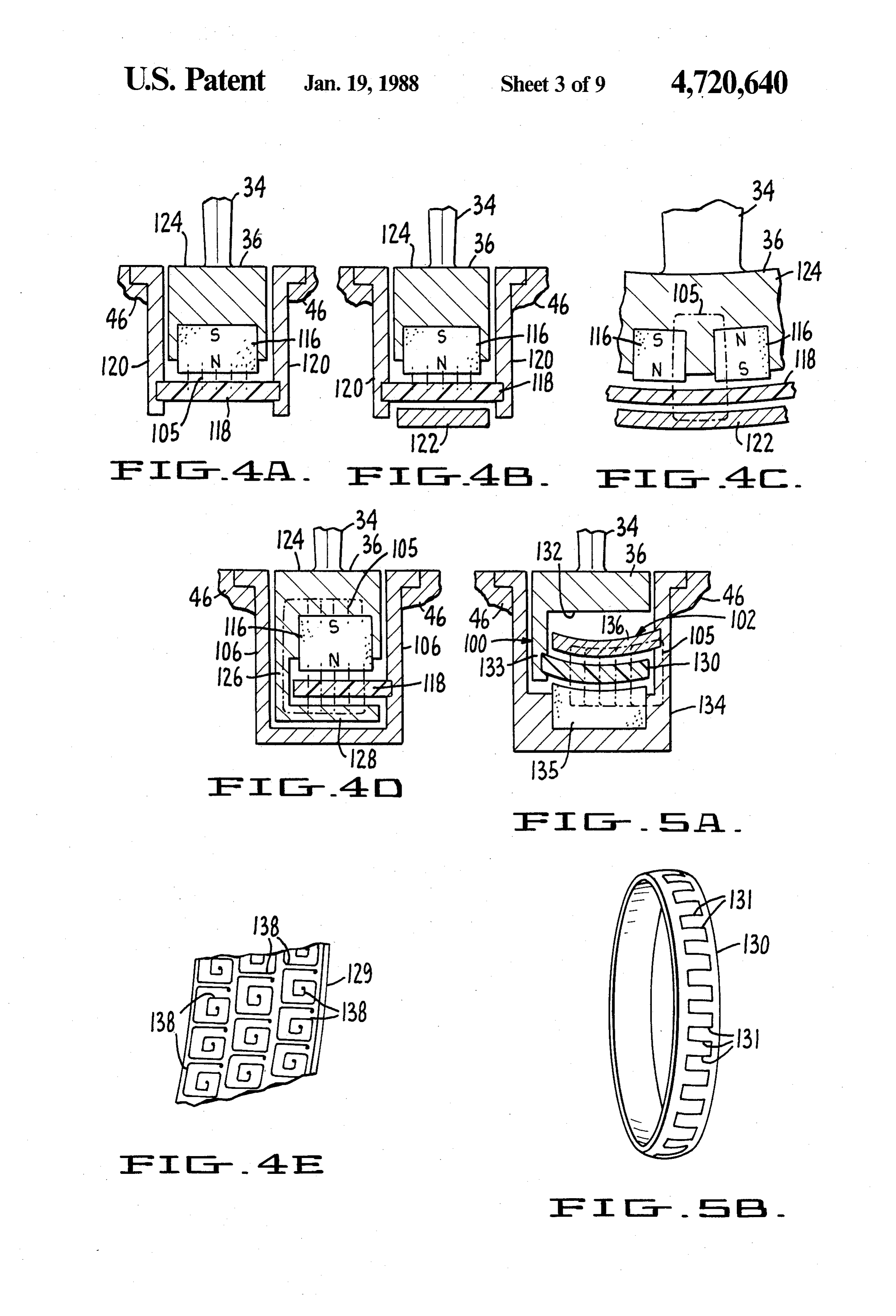
invention, the armature is a planar armature. FIG. 3E is an enlarged cross-sectional front view In accordance with still another aspect of the present taken along section line A-A of the FIG. 2 structure invention the armature is a tubular armature. showing details of a further embodiment of an are In accordance with still a further aspect of the present mature/magnet configuration having rotating field invention, the last aforementioned tubular armature is a magnet/keepers and a fixed planer armature. bi-curved armature so as to provide improved rigidity FIG. 3F is an enlarged cross-sectional side view of and constant field/armature gap distance with axial 65 the armature/magnet configuration of FIG. 3E. deflection of the impellor-rotor tip. FIG. 4A is an enlarged cross-sectional front view In accordance with still yet another aspect of the taken along section line A-A of the FIG. 2 structure present invention, the armature is mounted on the pe showing details of still a further embodiment of an ar
Page 13
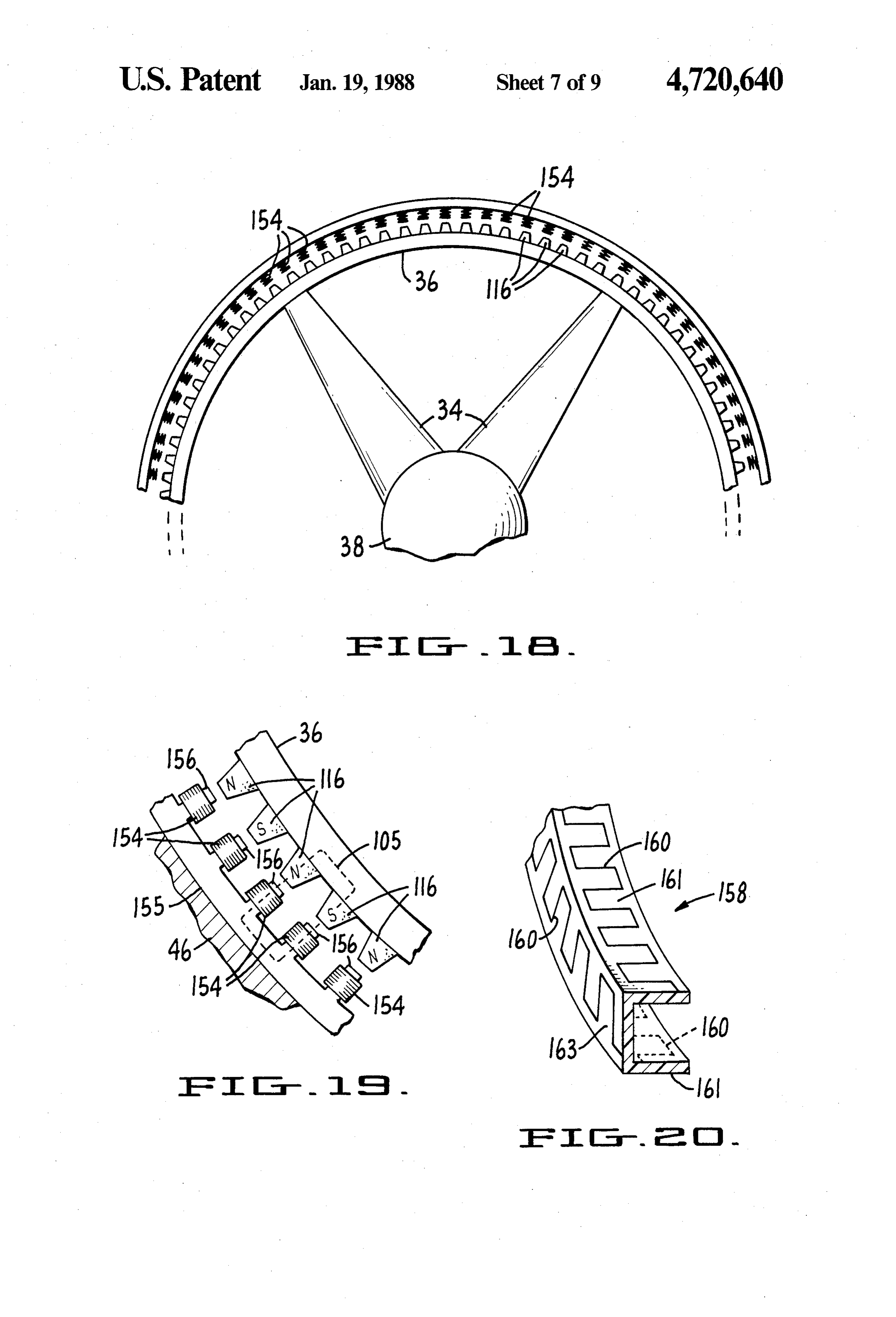
mature/magnet configuration having rotating field FIG. 18 is a fragmentary front view of an impeller magnets and a fixed mono-curved tubular armature. rotor carrying a plurality of field magnets and a plural FIG. 4B is an enlarged cross-sectional front view ity of associated coils which form a stationary armature. taken along section line A-A of the FIG. 2 structure FIG. 19 is an enlarged fragmentary view of the struc showing details of a variation of the FIG. 4A embodi- 5 ture of FIG. 18 showing the relative positions of the ment wherein the rotating field magnets are provided armature coils and field magnets.
with an associated non-rotating keeper. FIG. 20 of an alternative embodiment armature as FIG. 4C is an enlarged cross-sectional side view of sembly having three serpentine windings and a channel the armature/magnetic configuration of FIG. 4B. for receiving a field magnet structure which rotates FIG. 4D is an enlarged cross-sectional front view 10 relative to the armature assembly.
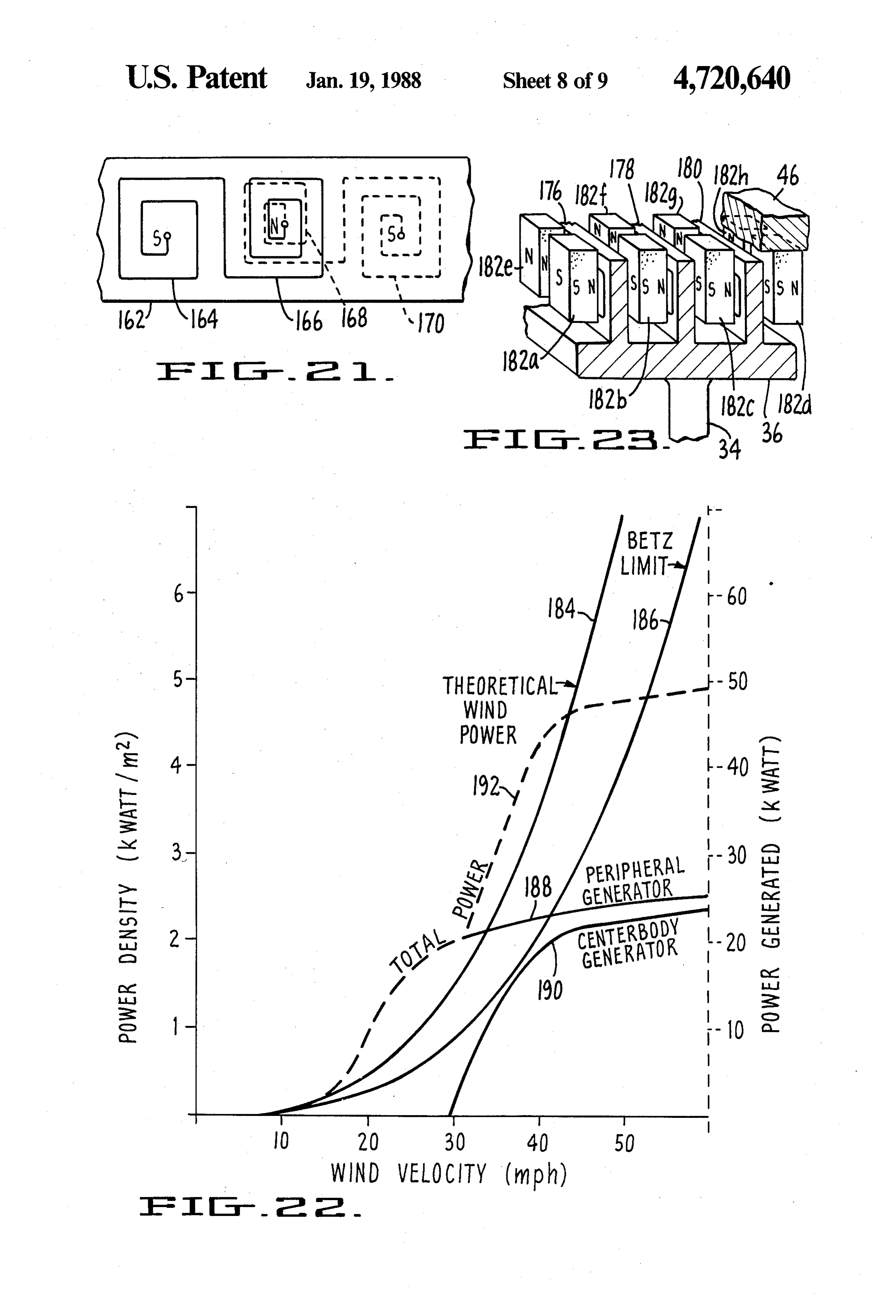
taken along section line A-A of the FIG. 2 structure FIG. 21 is a plan view of a section of a tubular arma showing details of a further variation of the FIG. 4A ture having an exemplary squaril windings printed on embodiment wherein the rotating field magnets are the inner and outer surfaces of the armature. provided with an associated rotating keeper. FIG. 22 is a graph depicting the relative outputs of a FIG. 4E is a fragmentary view of a section of the periphery and centerbody generators of a wind turbine tubular armature of FIG. 4D showing exemplary three for varying wind velocities.
phase squaril windings. FIG. 23 is a perspective view of a section of an impel FIG. 5A is an enlarged cross-sectional front view lor-rotor carrying three planer armatures and associated taken along section line A-A of the FIG. 2 structure fixed field magnets.
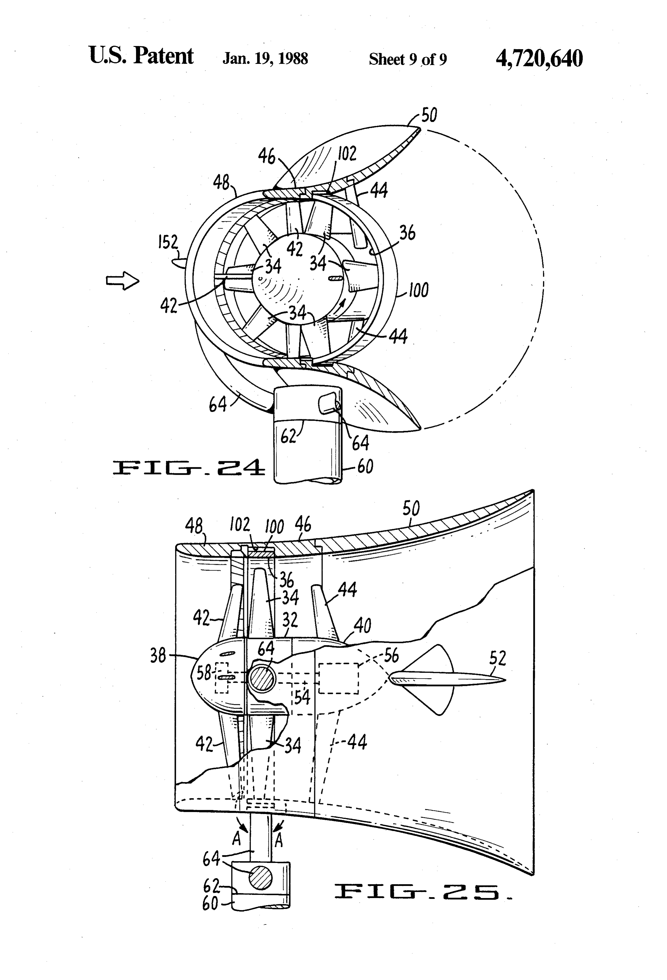
showing detail of an additional embodiment of an ar 20 FIGS. 24 and 25 are views similar to FIGS. 1 and 2, mature/magnet configuration having a rotating bi respectively, and illustrate an alternative embodiment curved tubular armature and fixed field magnets and an of the present invention.
associated fixed bi-curved keeper. DESCRIPTION OF THE PREFERRED FIG. 5B is a perspective view of the bi-curved tubu 25 EMBODIMENT lar armature of FIG. 5A showing an exemplary single phase serpentine winding. As set forth above and hereafter in the specification FIG. 6 is an elevational sectional view of a bullet and claims, the present invention relates in general to an profile diffuser-shroud as depicted in the present em axial flow fluid turbine alternator-generator assembly bodiment wind turbine of FIGS. 1 and 2 further includ 30 and parts thereof. The preferred embodiment is directed ing a concentrator structure. to a wind turbine generator as illustrated in FIGS. 1-2, FIG. 7 is an elevational sectional view of a conical 5A-5B and 15.
profile diffuser-shroud in accordance with still another Referring now to FIGS. 1-2 there is illustrated a aspect of the present invention. diffuser augmented wind turbine 9 having a central FIG. 8 is an elevational sectional view of a catenary 35 support structure 10 rotatably supporting an impellor profile diffuser-shroud in accordance with a further rotor 15 and supported via a plurality of radially extend aspect of the present invention. ing stanchions on an outer support structure or shroud FIG. 9 is an elevational partial sectional view of a 20 which is in turn gimbal mounted via gimbaled mast single wall catenary profile diffuser-shroud having an 64 which is connected via a rotatable joint 62 to the top associated slot ring in accordance with still a further 40 of a tower 60 so as to be self aligning in the wind or any aspect of the present invention. other flow stream.
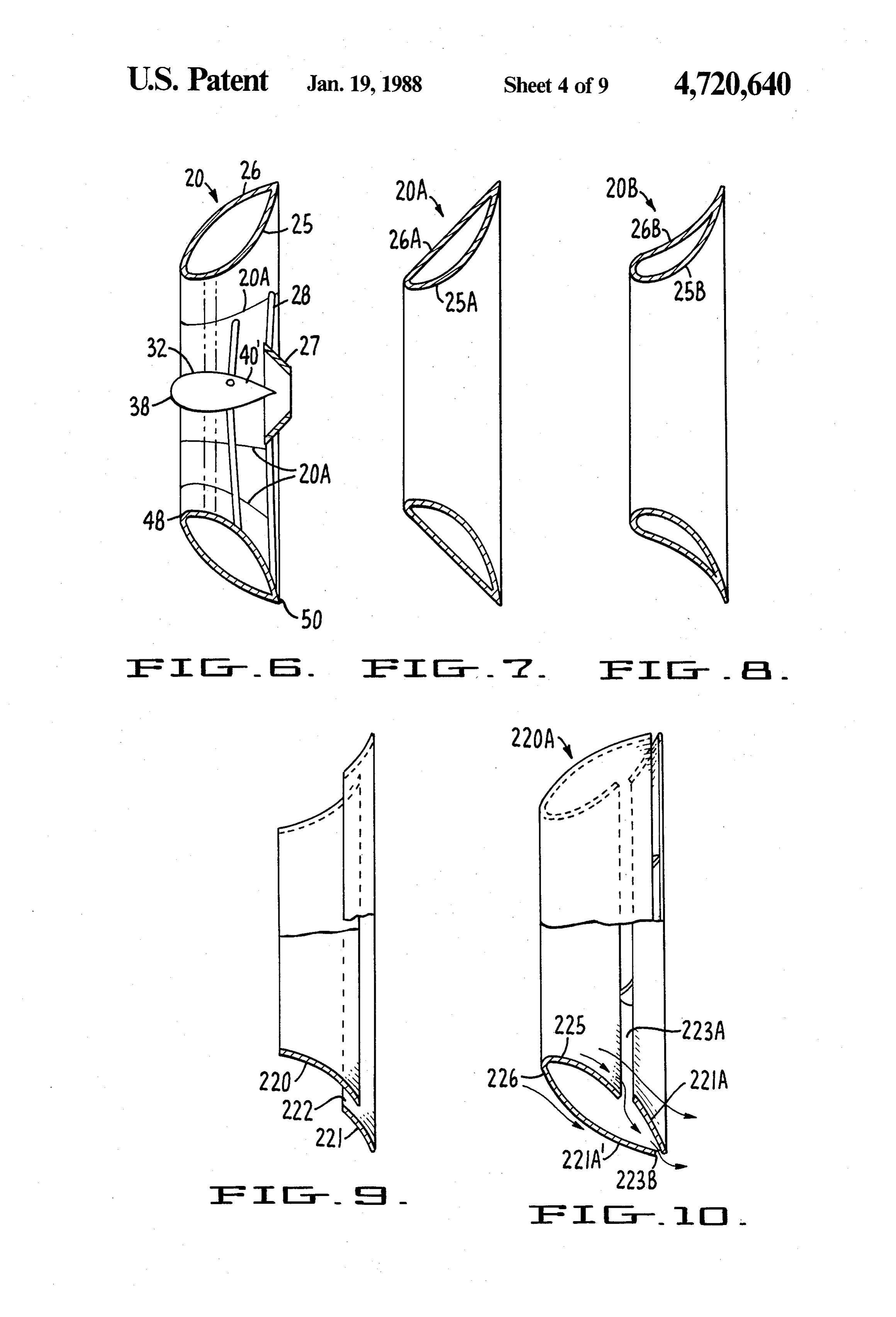
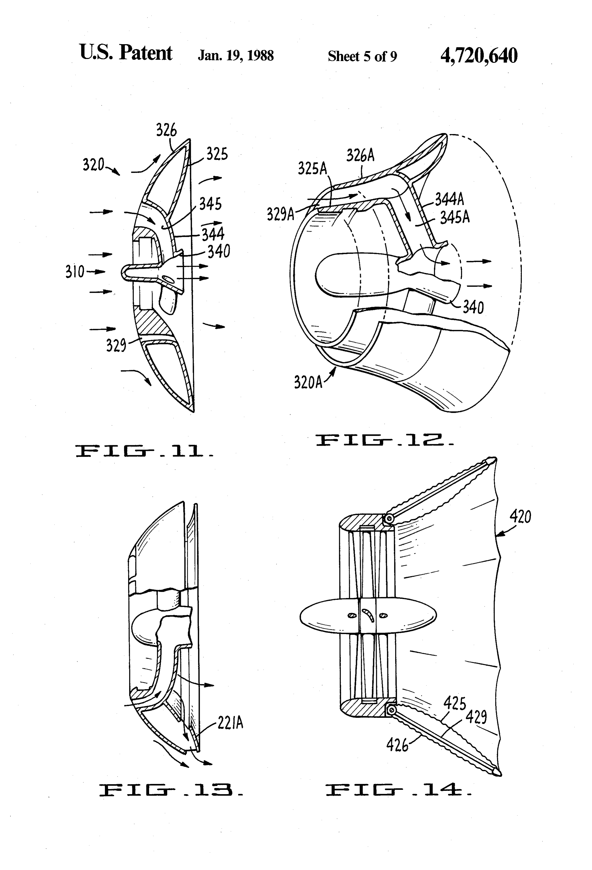
FIG. 10 is an elevational sectional view of a diffuser The central support structure 10 includes fixed up shroud which provides peripheral boundary layer con stream and downstream faired bodies or body portions trol in accordance with an additional aspect of the pres 38 and 40 respectively connected to stanchions 42 and ent invention. 45 fixed downstream stanchions 44 and rotatable support FIG. 11 is an elevational sectional view of a bullet ing the impellor-rotor 15 therebetween. The impellor profile diffuser-shroud which provides central bound rotor 15 has a central hub 32 connected via a plurality of ary layer control in accordance with a still additional circumferentially spaced-apart fluid dynamic blades 34 aspect of the present invention. to a radial outward ring member 36. Each of the blades FIG. 12 is a perspective view, partially broken away, 50 34 has the shape of an airfoil, and in the preferred em of a catenary profile diffuser-shroud which provides bodiment the airfoil blades have a positive angle of central boundary layer control in accordance with a attack at the central hub 32 with respect to the fluid still further additional aspect of the present invention. flow and a less positive angle of attack at the ring 36 FIG. 13 is an elevational sectional view of a bullet with respect to the fluid flow. profile diffuser-shroud which provides central and pe- 55 The outer support structure 20 is made up of a plural ripheral boundary layer control in combination. ity of separate members, including a central stator por FIG. 14 is a partial sectional view of an adjustable tion 46, an upstream inlet fairing 48 and a downstream diffuser-shroud and associated turbo cage. diffuser shroud 50.
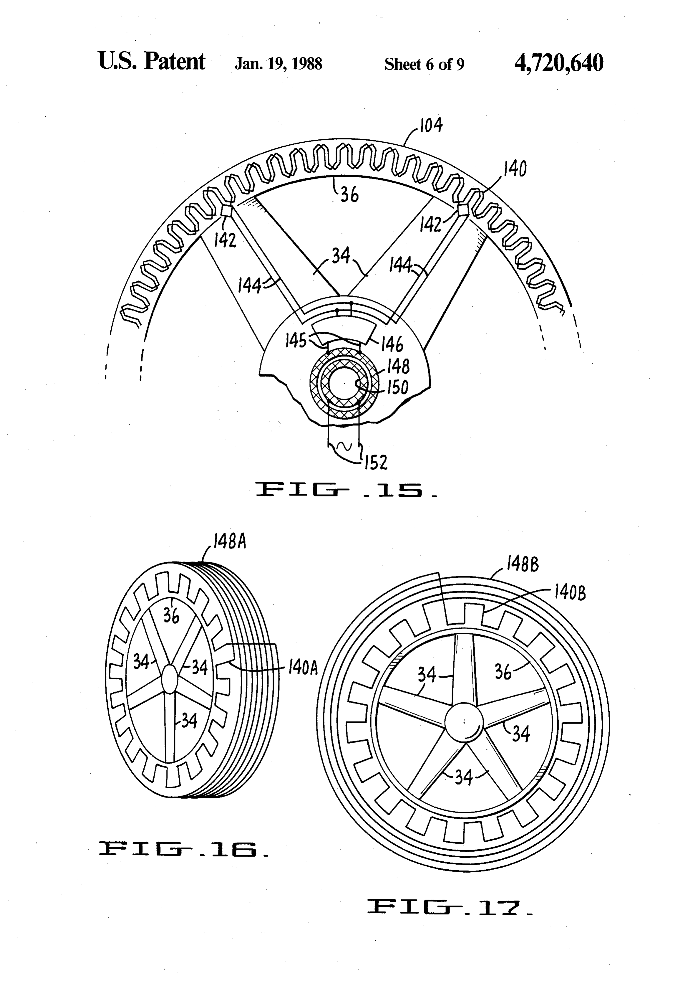
FIG. 15 is a fragmentary side view of an impellor The turbocage 30 through which the fluid stream rotor showing an armature winding and associated in- 60 passes includes the central hub 32, the blades 34, the ductive coupler. ring 36, the faired bodies 38 and 40, the stanchions 42 FIG. 16 is a schematic illustration of a perspective and 44 and the stator portion 46 of the outer support elevational view of an impellor-rotor depicting an arma structure. The outer support structure 20 is mounted on ture winding and associated transverse inductive cou a gimbaled mast 64 which is, in turn, supported on a pler primary winding. 65 tower 60. Gimbaled mast 64 permits the support struc FIG. 17 is a schematic illustration of a front view of ture to rotate about first and second orthogonal axes. an impellor-rotor depicting an armature winding and The first axis coincides with longitudinal axis of mast 60 inductive coupler primary winding which are coplanar. and intersects the axis of rotation of impellor-rotor 15.
Page 14
Stabilizers in the form offins or elevators 52 are pro armature substrate in the form of a ring or toroid. The vided on the outside of the outer support structure 20 inner periphery of the armature substrate is positioned for additional stability and air speed control. The center within a groove formed in the rotating ring member 36. of pressure of the outer support structure is offset and The armature substrate is fabricated from insulating downstream from the first axis of rotation of the struc materials including, for example, Fiberglass or Kapton ture on tower 60 so that the diffuser 50 will track the brand materials. The armature windings are formed on fluid stream. The turbocage and gimbaled mounting the substrate utilizing well-known printed circuit manu permit support of the wind turbine in various configura facturing methods so as to provide a light weight mono tions such as, for example, by suspension from a suspen lithic structure.
sion cable structure located in a high wind region across O A wide variety of windings can be utilized depending a valley. upon the desired electrical output. The windings may The Stabilizers 52 are movable to tilt the turbine out be arranged to provide a single phase output or a multi of the fluid flow stream when overspeed of the impel ple phase output. In addition, the windings may be lor-rotor 15 is sensed in the manner described below. printed on one or both sides of the armature substrate. Inside the central support structure 10 a rotor shaft 54 15 Multi-layer printed circuit board techniques may be is provided for rotation with the rotor 15. The rotor used to provide a wide variety of armature configura shaft 54 is connected to a central body generator assen tions. Exemplary printed circuit type armatures suitable bly 56 inside the downstream faired body 40 and a mo for use in the subject invention are disclosed in U.S. Pat. tor/tachometer overspeed sensor 58 is located in the Nos. 2,970,238 and 3,624,439, the contents of which are upstream faired body 38. Overspeed rotation of the hereby incorporated herein be reference. rotor 15 is sensed by the tachometer 58 and a control As can best be seen in FIG. 3B, planar armature 104 mechanism causes the stabilizer elevators 52 to turn and is disposed between opposing field magnets 108. Mag gradually tilt the outer support structure 20 out of the nets 108 are fastened to the interior sidewalls of a stator fluid flow stream. channel member 106. Member 106 is, in turn, positioned As shown in FIGS. 1 and 2 the outer support struc 25 in the central stator portion 46 of the outer support ture 20 is shaped as a toroid having a generally catenoid structure of the turbine (FIGS. 1 and 2). inner surface 25 and a generally parabolic outer surface Opposing field magnets iO8 are positioned a sufficient 26. The toroid airfoil creates a below-atmospheric pres distance apart so as to provide a small air gap between sure zone downstream while increasing the mass flow both sides of the rotatable armature and the magnets. through the turbine. This nonrotating duct structure 30 The poles of the facing magnets 108 are of opposite provides a diffuser section behind the rotor that pro polarity so as to produce a flux path, represented by duces power augmentation (typically 1.5 to 3 times). lines 105, which is normal to the surface of the armature The duct also lowers the cut-in windspeed by raising and to the direction of movement of the armature wind the level of axial fluid velocity significantly. It also ings 110. As can be seen in FIG. 3B, the polarity of dampens gusts while improving the wake created by the 35 magnets 108 along one side of the armature alternate, machine. The field magnets may be configured as depicted in The turbine 9 includes a rotor electrical generating FIG. 3C such that two alternating magnetic poles are element 100 and a stator electrical generating element provided by a single magnet 108a. A central notch or 102 located respectively on the impellor ring 36 and the cut out is formed in the center of magnets 108a so that stator portion 46, of the outer support structure 20. the flux path will be concentrated at the extreme ends of The subject invention preferably utilizes a monolithic the magnets, as represented by the flux line 105. Alter armature construction having a low moment of inertia. nately, the magnets may be appropriately magnetized so As will be subsequently described, such an armature as to concentrate the flux in the same manner. may be constructed in accordance with well-known An alternative field magnet configuration is shown in printed circuit and chemical milling technology. The 45 FIG. 3D. Relatively small magnets 108b are positioned necessary magnetic field may be produced utilizing along the interior of stator channel member 106 having electromagnets or, preferably, permanent magnets. alternating polarities. In this alternative configuration, In many applications, especially when the driving channel member 106 acts as a keeper, i.e., flux guide, fluid is air, it is preferable that the rotor generating and is present in the flux path, as represented by line element 100 include the armature and that the stator 50 105. Accordingly, member 106 is fabricated from a element 102 include the relatively large mass magnets. ferromagnetic material such as iron or an iron alloy The generator will then have a low moment of inertia so such as Metglas brand material.
that the generator will be capable of rapidly responding Conventional brushes and slip rings or the like (not to wind gusts and the like. depicted) can be utilized for removing the electrical In other applications, it may be preferable that the 55 energy produced in the rotating armature. Preferably, rotor generating element 100 have a high moment of an induction coupler arrangement, as will be subse inertia so as to produce a flywheel action. By way of quently described, is used in lieu of brushes and other example, if output frequency is to be maintained con similar friction producing elements.
stant, such flywheel action will tend to reduce rapid FIGS. 3E and 3F depict a further embodiment of an variations in the rotor speed. The inertia of the rotor armature/magnet configuration having a rotating gen will have the effect of weighing or damping the appare erating element 100 in the form offield magnets 116 and ent velocity of the fluid flow. In that event, the rotor a stator generating element 102 in the form of a planar generating element 100 will comprise the field magnets armature 112. Since the armature is not rotating, there is and the stator generating element 102 will comprise the no requirement for brushes and the like. attature. 65 Rotating element 100 includes a rotor channel mem Referring now to FIGS. 3A-3D, a fluid turbine hav ber 114 which is an integral part of ring member 36. A ing a rotating armature and fixed field magnets is series of spaced-apart rectangular recesses (not desig shown. The armature 104 is a planar armature having an nated) are formed in one sidewell of member 114 for
Page 15
receiving individual permanent magnets 116. As can prepared. The substrate is in the form of a narrow strip best be seen in FIG. 3F, magnets 116 are positioned having a width equal to the desired width of the arma within the recesses with alternating polarity poles fac ture and a length equal to the desired circumference of ing the opposite sidewall of member 114. Two consecu the armature. The winding pattern is then produced on tive alternating poles may be provided by a single mag 5 the substrate by etching away unwanted portions of the net having a central cut-out, as previously described in metalized layer. Examples of various windings will be connection with the FIG. 3C embodiment. Alterna subsequently described.
tively, consecutive alternating poles may be produced Once the armature windings have been etched, the by separate magnets, as discussed in connection with narrow substrate is positioned over a circular mandrel the FIG. 3D embodiment. O having a diameter equal to that of the desired armature Stator generating element 102 includes a stator chan diameter. The free ends of the substrate are then se nel member 106 which is secured within the central cured together to form a continuous loop or tube. The stator portion 46 of the outer support structure in the final product is a lightweight monolithic tubular arma same manner as the embodiment of FIGS. 3A-3D. A ture.
groove (not designated) is formed in the central area of 15 Referring back to FIG. 4A, a circular groove is ma bottom wall of channel member 106 for receiving the chined on opposite sides of the inner walls of support inner periphery of a planar armature 112. Armature 112 member 120. The thickness of the grooves is slightly is similar in construction to armature 104 of the previ greater than the substrate thickness of the armature so ously-described embodiments. that the armature is held securely in place. Armature 112 is disposed within the air gap formed 20 The flux lines 105 produced by magnets 116 are gen between magnets 116 and the sidewall of rotor channel erally transverse to the windings of the tubular arma member 114 with member 114 serving as a keeper. A ture. Accordingly, as the permanent magnets 116 rotate flux path, represented by lines 105, is produced which with the impellor-rotor, electrical energy is produced in travels from the North pole of magnet 116 through the tubular armature 118.
armature 112 to the sidewall of channel member 114 on 25 A further variation of the FIG. 4A embodiment of the opposite side of the armature. The path continues the subject invention is shown in FIGS. 4B and 4C. This through the wall member to a location opposite an embodiment is similar in construction to the FIG. 4A adjacent South magnetic pole. It should be noted that, embodiment except that a fixed tubular keeper (flux as in the case of the other embodiments of the subject guide) 122 extends around and is slightly spaced apart invention, the fluid dynamic blades are disposed outside 30 from armature 118. Keeper 122 is rigidly secured within of the flux path and may, therefore, be made from mate central stator portion 46.
rials which are non-magnetic. As can best be seen in FIG. 4C, the flux path, repre In the event a single magnet (FIG. 3C) provides two sented by lines 105, extends from the North pole of a adjacent poles, the path continues through the armature first magnet 116 and through tubular armature 118 to and to the adjacent South pole and then through the 35 keeper 122. The path continues through the keeper to a magnet back to the North pole. If separate magnets are location opposite the South pole of the adjacent magnet used for each pole (FIG. 3D), the flux path will extend 116. The flux passes again through armature 118 and back through the armature and continue through the enters adjacent magnet 116 through the South pole, adjacent magnet from the South to the North pole thereof, and to the North pole. The flux then travels thereof, through the sidewall of member 114. The path from the North pole, through support member 124, and continues back to the South pole of the first magnet and back to the South pole of the first magnet. then through the first magnet to the North pole thereof, A variation of the FIGS. 4B-4C embodiment is de thereby completing the path. Inasmuch as member 114 picted in FIG. 4D. A stator channel member 106, simi functions as keeper and carries at least part of the flux in lar to member 106 of the FIG. 3A embodiment, is se either embodiment, member 114 should be fabricated 45 cured to central stator portion 46. A circular groove is from a ferromagnetic material. formed in the lower portion of the inner sidewall of Referring now to FIG. 4A, a further embodiment of member 106 for receiving a tubular armature 118 to an armature/magnet configuration of the subject inven form the stator generating element. tion may be seen. This embodiment is similar to the The rotor generating element includes a rotor field embodiment of FIGS. 3E and 3F to the extent that the 50 magnet support member 124 which forms an integral rotor generating element 100 includes the field magnets part with ring member 36. A channel 126 is formed and the stator generating element 102 includes the ar almost the entire width of member 124 so as to form a nature. flange 128 which forms part of the keeper. A series of A rotor field magnetic support member 124 is pro adjacent recesses are formed in the sidewall of channel vided which forms an integral part of the outer periph 55 126, opposite flange 128. Permanent field magnets 116 ery of ring member 36. A series of recesses are formed are positioned within the recesses, with the axes of the in member 124 for receiving permanent magnets 116. magnets being radially disposed with respect to the axis The magnetic axes of the magnets are radially aligned of rotation of the impellor-rotor. Adjacent magnets 116 with the axis of rotation of the turbine impellor-rotor, have opposite polarity poles facing channel 126. Tubu with the magnetics being positioned around ring mem lar armature 118 is positioned within channel 126 with a ber 36 with alternating polarities. Small air gap being formed between the armature and A pair of spaced apart and opposing stator armature the field magnets.
support members 120, mounted on central stator por FIG. 4E shows a section of the tubular armature tion 46, are included for supporting a tubular armature utilized in the FIG. 4D apparatus depicting exemplary 118. Tubular armature 118, like the previously 65 armature windings. The individual printed windings described planar armature 104, is preferably manufac 138 are in three circumferential rows. The windings in tured utilizing conventional printed circuit technology. a row may be connected either in series or in parallel, An insulating substrate having a metalized layer is first depending upon the desired electrical output. The indi
Page 16
vidual windings shown are referred to as squaril wind been etched, the strip is passed over a curved mandrel ings. The term squaril winding, as used herein, refers having a radius of curvature equal to the desired radius collectively to a spiral-type of winding having either a of curvature of the cross-section of the armature in the generally rectangular shape or a generally square shape. plane parallel to the axis of armature rotation. In the event the squaril winding is to have a generally Once the strip has been passed over the curved man rectangular shape, linear conductor segments make up drel, thereby imparting an arcuate shape across the the coil in a manner such that, if proceeding from the width of the strip, the strip is then positioned over a coil center, each coil segment is long enough to round circular mandrel in the same manner as the mono the previous segment by the gap width between adja curved tubular armature. The two ends of the strip are cent turns, so as to maintain uniform spacing of the coil 10 then secured together, thereby completing the con segments. Each segment is positioned at 90 degrees to struction of the armature.
the previous segment, producing a right or left hand The printed winding 131 depicted in FIG. 5B is a turn oriented coil. Coils can be combined in parallel or serpentine winding. Although only a single phase wind in series as required. ing is shown, additional windings could be used to pro In the event the squaril winding is to have a generally 15 vide a multi-phase output. The additional windings may square shape, the linear conductor segments make up be positioned adjacent one another as depicted in the the coil in a manner such that, if proceeding from the FIG. 4E armature. Alternatively, the windings may be coil center, the first segment is two conductor widths in superimposed over one another utilizing multi-layer length, the second segment is two conductor widths printed circuit fabrication techniques. This approach plus one gap width and the third segment is equal to the 20 may also be utilized in connection with the previously previous segment plus one conductor width. Each addi described mono-curved tubular armatures and the pla tional segment length is equal to the previous length nar armatures. Other winding configurations could also plus one gap length added to every even segment and be used.
one conductor width added to every odd segment thus Referring back to FIG. 5A, the bi-curved armature increasing the conductor segment lengths moving out 25 130 forms part of the rotor generating element 100. The to the coil periphery. Each segment is positioned at 90 periphery of the armature is received in a circular degrees to the previous segment, producing a right or groove formed in a flange 33. Flange 133 extends away left hand turn oriented coil. Coils can be combined in from an armature support member 132 which forms an parallel or in series as required. integral part of ring member 36. Other windings could also be used such as spiral 30 The stator generating element 102 includes a stator windings and serpentine windings. Spiral windings are channel member 134 secured to the central stator por similar to squaril windings except that the individual tion 46. The bottom portion of member 134 is provided turns are generally circular rather than square. An ad with a series of recesses for receiving field magnets 135 vantage of squaril windings over spiral windings for having alternating polarity poles facing armature 130. generally tubular geometry armatures is that all of the 35 Magnets 135 preferably have an arcuate surface facing available area can be filled by conductor material. Ex armature 130 with a radius of curvature equal to the emplary serpentine windings will be subsequently de cross-sectional radius of curvature of the armature so scribed. that an air gap is formed between the magnets and the The three circumferential rows of winding 138 pro armature which is uniform across the width of the arma vide a three-phase electrical output. The position of the 40 ture.
coils in one row is typically shifted with respect to the A keeper flange 136 is mounted on a sidewall of mem coil in an adjacent row such that electrical outputs of ber 134 which extends substantially across the full the rows differ in phase by 120 degrees. Fewer or width of armature 130. Keeper flange 136 has an arcuate greater numbers of rows can be utilized to decrease or cross-section so as to maintain a uniform flux path increase the number of phase-shifted outputs, as desired. 45 across the width of the armature. Keeper flange 136 The flux path 105 of the FIG. 4D embodiment is could be replaced with a magnet array similar to that similar to that of the FIG. 4C embodiment. The princi depicted in FIG. 3A.
pal distinction is that keeper 122 of the FIG. 4C embodi The FIG. 5A construction inherently compensates ment is stationary, whereas keeper 128 of the FIG. 4D for flexing which occurs when the impellor-rotor is embodiment rotates with the field magnets 116. 50 loaded. Such flexing tends to cause the armature 130 to The tubular armatures 118 depicted in FIGS. 4A-4D pivot normal to plane of impellor-rotor rotation can be referred to as mono-curved tubular armatures towards one or the other sidewall of channel support inasmuch as the cross-sections of the armatures are member 134. As a result of the arcuate cross-sections of curved in the plane normal to the impellor-rotor axis of armature 130, keeper flange 136 and magnets 135, the rotation and are flat in the plane parallel to the axis of 55 flux path remains relatively constant in the presence of rotation. The rigidity of a tubular armature can be im such impellor-rotor pivoting.
proved substantially by curving the cross-section in As previously noted, electromagnets may be utilized both planes. One such armature, referred to as a bi in lieu of permanent field magnets. In the event the curved tubular armature, is depicted in the embodiment electromagnets form part of the rotor generating ele of FIGS. 5A and 5B and is the preferred embodiment ment, the windings of the electromagnets are preferably anature. supported by a tubular substrate similar to the substrate The bi-curved tubular windings are manufactured in of the previously-described tubular armatures. Simi substantially the same manner as the mono-curved larly, the windings of the electromagnet are preferably windings utilizing conventional printed circuit technol squaril windings, although other windings such as spiral ogy. A substrate having a metalized layer is first pre 65 windings could be used.
pared having a width-equal to the desired width of the While the outer support structure or shroud 20 can be tubular armature and a length equal to the circumfer solid as shown in FIGS. 1-2, it can also be hollow as ence of the armature. Once the winding pattern has shown in FIG. 6. The upstream inlet fairing 48 and
Page 17
downstream shroud 50 can be circumferentially seg Fluid carried outside the principal inlet opening into the mented along gore lines 20A for assembly of large tur turbocage is carried into and through the turbocage bines. Also as shown in FIG. 6, a concentrator in the with a major portion discharged at the downstream end form of a hollow truncated cone 27 supported on stan of the central support structure. FIGS. 11-13 illustrate chions 28 can be positioned downstream of the modified alternative ways of conducting this fluid. In accordance downstream body portion 40'. The concentrator accel with the embodiment illustrated in FIG. 11 passages 329 erates the central core wake, postponing diffuser stall. are provided through the shroud from the outer surface Although stanchion 28 is shown supported on the outer 326 to the inner surface 325 for passage of fluid there support structure, it can alternatively be supported by through and along the inner surface 325, and passages body portion 40'. O 345 are provided through the shroud surfaces 326 and The FIGS. 1 and 2 embodiment shroud has a bullet 325 and within the hollow support stanchions 344 for shaped profile, which is the presently-prefered profile. venting axially out of the downstream end of the down This profile provides reduced overall drag. The convex streambody portion 340 of the central support structure catenoid inner surface 25 expands the air as the airflows 310. The hollow support stanchion flow postpones cen over the surface, thereby causing the air pressure at the 15 tral core stall.
downstream portion of the surface to decrease below Alternatively, as shown in FIG. 12, a hollow annular atmospheric pressure. chamber 329A is provided between the inner and outer As the air travels over the outer convex parabolic surfaces 325A and 326A respectively of the shroud surface 26 toward the trailing edge, the air velocity 320A and communicates with passages 345A through increases while the air pressure decreases. The decreas 20 hollow stanchions or ventilator tubes 344A for convey ing air pressure of the outer surface pulls the interior air ing fluid injected into the annular chamber 329A near mass away from the center of the diffuser, thereby pro the radial outward portion of the upstream inlet fairing viding the desired lower air pressure. of the outer support structure 320A and leading to the FIG. 7 shows another configuration for the outer inlet to the hollow stanchion 344A.
support structure or diffuser/shroud 20A. Shroud 20A 25 FIG. 13 illustrates a shroud-turbocage structure that has a convex catenoid inner surface 25A similar to that combines features of the shroud segment 221A of FIG. of FIGS. 1-2 and 6. The outer surface 26A is in the form 10 with the vented shroud structure 320 hollow sup of a truncated core. One advantage of this construction port stanchions 344 of FIGS. 11 and 12. The ventilator is reduced construction costs. tubes accelerate the central core wake and postpone the FIG. 8 depicts still a further configuration of the 30 diffuser stall as in the FIG. 11 embodiment and the slot diffuser shroud 20B. Diffuser/shroud 20B has a convex provides the diffuser wall boundary layer control en catenoid inner surface 25B similar to that of FIGS. 1-2, hancement of the FIG. 10 embodiment. 6 and 7 and a concave catenoid exterior surface 26B. As shown in FIG. 14 the diffuser shroud 420 can be The concave outer surface 26B causes the air pressure hollow and the inner and/or outer surfaces 425 and 426 to increase as the air moves along the surface, thereby 35 of the shroud formed of a flexible material for flexure slowing the air flow. The pressure increase is vented with fluid flow through the apparatus. As showh in into the interior at critical boundary layer separation FIG. 14 both the inner and outer surfaces 425 and 426 points so as to increase the interior flow velocity and respectively are formed of a flexible material such as, prevent diffuser stall. for example, polyvinylchloride, supported on a frame Alternatively, the shroud can be formed of a single structure 429 whereby the surfaces of the diffuser member of uniform cross section, as the shroud 220 shroud can flex to conform to the changing conditions shown in FIG. 9, wherein the shroud shape is generally as the fluid velocity through the shroud increases or a catenoid. This shroud is easier and less expensive to decreases such that the stall condition is postponed, manufacture than certain other configurations dis suppressed or eliminated.
closed. 45 It is even possible to control the pressure inside a FIG. 9 also illustrates the addition of an outside dif hollow shroud having a flexible surface material such fuser shroud segment 221 spaced by a slot ring 222 that the configuration of the surface will change de surrounding the downstream end of the shroud 220 and pending upon the relationship of the pressure within the shaped generally as a catenoid for boundary layer, flow shroud relative to the pressure on the outside surface of separation, control at the downstream end of the shroud 50 the shroud. The pressure inside the shroud 420 can be 220. This shroud segment 221 and slot ring 222 intro changed in accordance with different operational char duces high velocity air into the downstream end of the acteristics of the turbine measured such as by the speed shroud to increase the velocity within the shroud. of the rotor or the pressure sensed at the surface of the FIG. 10 shows an alternative configuration for the shroud.
shroud 220A having inside and outside surfaces 225 and 55 As previously described, in the event rotor generat 226 similar to the surfaces 25 and 26 of FIG. 6. A ing element 100 includes the armature, it is necessary to curved shroud segment 221A supported by a plurality utilize brushes or the like to transfer electrical energy of webs 221A" provides a gap 223A at critical boundary from the armature to a non-rotating environment. FIG. layer separation points of inner surface 225 and a gap 15 shows a planar armature 104 forming part of a rotor 223B at the downstream end of outer surface 226 so that generating element and associated structure in combina boundary layer fluid can flow into gap 223A and out tion with an inductive coupler device for transferring gap 223B. This gap or slot provides a further improve electrical energy.
ment of boundary layer control of the diffuser wall and Armature 104 is a planar armature having a pair of results in increased low pressure and best augmentation. printed serpentine windings 140. The field magnets, In accordance with another aspect of the present 65 which form part of the stator generating element 102, invention the diffuser shroud can be vented to postpone, are not depicted. The planer armature is supported on a suppress or eliminate the stalled condition in operation ring member 36 which is, in turn, supported by impel by injecting or passing fluid through the shroud wall. lor-rotor blades 34.
Page 18
A rectifier circuit 142, such as a diode bridge, is pro secured to ring member 36 which is supported by impel vided for each of the winding phases 140. The rectifier lor-rotor blades 34.
circuits 142 convert the A.C. outputs of winding 104 to Magnets 116 are positioned with alternating polarity D.C. The outputs of the two rectifier circuits are con poles facing armature coils 154. In order to minimize nected in parallel by conductors 144 which are sup 5 detent, starting torque and cogging, the spacing of the ported by blades 34. Conductors 144 carry the D.C. magnets and coils is such that all magnets and coils are output to the input of a conventional inverter circuit never simultaneously facing one another at any rota 146 located near the axis of rotation of the impellor tional position of the impellor-rotor. This is true in all Otor. embodiments of the subject invention. Inverter 146, which can be powered by the D.C. O Coils 154 are wound around pole pieces 156 which input, converts the D.C. input to a relatively high free form an integral part of a circular keeper 155. Keeper quency A.C. power which appears on inverter output 155 is, in turn, supported on central stator portion 46. lines 145. Lines 145 are connected to the rotating pri mary winding 148 of an inductive coupler, with the jectIninvention addition to planar and tubular armatures, the sub may be implemented utilizing a channel coupler being equivalent to a power transformer. In 15 armature generally designated by the numeral 158, as verter 146 and the associated rectifiers can be deleted in the event, for example, the output frequency is within a produced utilizing Channel depicted in FIG. 20. armature 158 is preferably range to provide efficient coupling through the induc niques. The armature has acircuit printed fabrication tech
tive coupler. However, the inverter permits the output which is defined by spaced-apart parallel members 161, frequency and voltage amplitude to be readily con 20 and intermediate member 163 which bridges members trolled.
The secondary winding 150 of the inductive coupler the 161. Parallel members 161 are preferably constructed in is mounted on the non-rotating portion of the structure, same manner as the previously-described tubular encircled by the rotating primary winding 148. The armature the same 118 and bridging member 163 is preferably in manner as the previously-described planar relatively high frequency A.C. power output of the armatures 104
secondary winding on lines 152, can then be utilized as desired. Parallel members 161 and bridging member 163 each FIG. 16 is a schematic drawing of another armature carry picted a printed winding 160. In the configuration de in FIG. 20, serpentine windings are used which structure and associated apparatus utilizing an inductive coupler. The configuration includes a planar armature 30 are positioned relative to one another so as to provide a three-phase output, with each phase shifted 120 degrees mounted on a rotating ring member 36 which is, in turn, from the remaining two phases. supported on impellor-rotor blade 34. The planar arma ture includes a single serpentine winding 140A although A field magnet array (not depicted) is disposed within other winding arrangements may be utilized. the channel formed by elements 161 and 163 of arma The FIG, 16 apparatus further includes a winding ture 158. The magnets are arranged to provide alternat
i48A which forms the primary of an inductive coupler. ing flux paths which are normal to the surfaces of ele Winding 148A is printed on a substrate similar in con ments 161 and 163. Keepers may also be included. Ar struction to the substrates of the previously-described mature 158 may be utilized as part of either the stator tubular armatures utilizing printed circuit technology. generating element or the rotor generating element. Accordingly, the substrate of the planar armature is FIG. 21 depicts a further exemplary armature wind generally orthogonal with respect to the inductive cou ing configuration which may be utilized in connection pler primary winding substrate. with the previously-described armatures. Each winding Primary winding 148A of the FIG. 16 configuration segment is comprised of a total of four separate squaril is in the form of a spiral having a diameter equal to the windings connected in series.
outer diameter of the armature. Armature winding 45 A first squaril winding 164 is printed on a first side of 140A and primary winding 148A are inductively cou the armature substrate. A second squaril winding 166 is pled with the secondary winding (not depicted) being located adjacent winding 164. Winding 166 is also positioned on the stator element and encircling the printed on the first side of the substrate, but the direc primary winding. An inverter, associated rectifiers and tion of winding 166 is opposite to that of winding 164. A other power circuits can be added. 50 third winding 168 is printed on the second side of the The orthogonal relationship between the armature substrate, opposite winding 166. Winding 166 and 168, winding 140A and primary winding 148A minimizes the which have the same turn direction, are connected coupling between the two elements thereby reducing together through the substrate. A fourth winding 170 is distortion on the power output. FIG. 17 shows an alter printed on the second side of the substrate, adjacent native configuration where the armature windings 140B 55 winding 168. Winding 170 is connected to winding 168 and primary winding 148B of the inductive coupler are with the turns being wound in opposite directions. printed on a common planar substrate. Again, the arma The field magnets used in connection with the FIG. ture winding and primary winding are connected in 21 winding configuration are positioned with adjacent parallel. The stationary secondary winding (not de magnets having opposite polarity poles facing the arma picted) is positioned adjacent the rotating substrate ture. For the armature/magnet position depicted in which carries the armature and primary windings. An FIG. 21, the flux path extends from the north pole of the inverter, associated rectifiers and other power circuits magnet facing windings 166 and 168, through the two can be added. windings and back through winding 164 to the south FIGS. 18 and 19 show a further stator/rotor configu pole of the magnet opposite winding 164. Similarly, a ration having a rotor generating element which carries 65 second flux path extends from the north pole of the a series of spaced-apart permanent magnets 116 and a magnet opposite windings 166 and 168, through the two stator generating element which includes an armature windings, and back through winding 170 to the south comprised of a series of coils 154. Magnets 116 are pole of the magnet opposite the winding.
Page 19
A still further armature/field magnet configuration of augmented wind turbine in accordance with the previ the subject invention is shown in FIG. 23. The FIG.23 ously noted Betz limit.
configuration is adapted to provide a three-phase out Exemplary peripheral generator and centerbodygen put. Three spaced-apart planar armatures 176, 178 and erator power outputs for varying wind velocities are 180 are coaxially mounted on a ring member 36 which 5 represented by curves 188 and 190, respectively. It can is secured to blades 34 of the impellor-rotor. An array of be seen for the two curves that the peripheral generator permanent field magnets is positioned on the central output is greater than that of the centerbody output, stator portion 46 adjacent the planar armatures. especially for lower wind velocities. Curve 192 repre A first circumferentially aligned set of magnets, in sents the sum of the power produced by the two genera cluding magnets 182a and 182e, are positioned adjacent 10 tOS.
armature 176. The magnets are positioned with alternat The FIG. 22 graph shows the generator outputs ing polarities. A second set of magnets, including mag when both generators are permanently engaged. As nets 182b and 182f; are positioned between armatures previously noted, it is preferably that the centerbody 176 and 178. The magnet of the second set are also of 15 generator be disengaged until the peripheral generator alternating polarity, with the polarity of the magnets output reaches a predetermined rated power output being opposite to that of adjacent magnets of the first level. In the example depicted in the graph, overall Set. efficiency will be achieved if the centerbody generator A third set of alternating polarity magnets, including remains inactive until the wind velocity reaches approx magnets 182c and 182g, is disposed between armatures imately 30 miles per hour.
178 and 180. A fourth and final set of alternating polar 20 FIGS. 24 and 25 illustrate a fluid turbine assembly ity magnets, including magnets 182d and 182h, is posi similar to that of FIGS. 1 and 2 but with a more elon tioned adjacent armature 180, opposite the third set of gate shroud having a catenary configuration 8 and 10. magnets. The magnets of the third set are positioned Preferably, the diameter of the downstream end of dif. with polarities opposite to the magnets of the second set 25 fuser shroud 50 is at least twice the diameter of the and the magnets of the fourth set are positioned with upstream end of inlet fairing 48. The axial length of the polarities aligned in the same manner as the second set outer support structure is also preferably less than or magnets and opposite to that of the third set. equal to one and one-half times the diameter of the Magnets 182 produce a flux path which is transverse upstream end of inlet fairing 48.
to the planar armature. An exemplary path starts at the 30 Thus several embodiments of a novel fluid powered North pole of magnet 182a and extends through arma turbine generator have been disclosed. Although such ture 176 to the South pole of magnet 182b. Then from embodiments have been described in some detail, it is to the North pole of magnet 182b path continues through be understood that various changes can be made by armature 178, through magnet 182c, through armature persons skilled in the art without departing from the 180 to magnet 182d. The path then turns and enters the 35 spirit and scope of the invention as defined by the ap South pole of magnet 182h. The path passes through pended claims.
magnet 182h, armature 180, magnet 182g, armature 178 We claim:
and through magnet 182f The path continues through 1. An axial flow fluid turbine generator apparatus armature 176, magnet 182e and back to magnet 182a. comprising, in combination:
As previously noted, the peripheral generator formed 40 a central support structure;
by rotor generating element 100 and stator generating a hollow outer support structure surrounding and element 102 (FIGS. 2 and 25) produces a significant connected to said central support structure and power output at relatively low rotational velocities adapted to pass a steam of fluid between said sup without the use of gears and the like. Centerbody gener port structures;
ator 56 produces significant power output at relatively 45 an impellor-rotor rotatably mounted on said central higher rotational velocities. support structure;
Preferably, apparatus is provided (not depicted) to said impellor-rotor having a plurality of circumfer sense when the peripheral generator has reached its entially spaced non-magnetic fluid dynamic rated power output. Such output is typically the point at blade means for transferring energy from the which any further increase in power is likely to exceed 50 stream of fluid; and design limitations. Once the predetermined output is a ring connecting the radial outward end of said sensed, the field of the centerbody generator 56 is acti blade means;
vated thereby loading down the rotor while increasing said impellor-rotor including a central hub portion the total power output without damaging the turbine. connected to the radial inward end of each of The apparatus could also monitor fluid velocity for the 55 said blade means and each of said blade means purpose of controlling centerbody generator 56. having the shape of an airfoil, said airfoil having The graph depicted in FIG. 22 further illustrates the a positive angle of attack at said central hub combined effects of the peripheral and centerbodygen portion and an angle of attack at said ring less erators for a wind-powered turbine. The left-hand verti than said positive angle at said central hub por cal axis represents the power density of the wind in 60 tion.
units of kilowatts per square meter. The right-hand 2. The apparatus of claim 1 wherein said ring includes vertical axis represents the power output of the two an armature coil.
turbine generators in kilowatts. The horizontal axis 3. The apparatus of claim 2 wherein said armature represents the wind velocity in miles per hour. coil is a printed circuit.
Curve 184 indicates the theoretical power density of 65 4. The apparatus of claim 2 wherein said armature the wind for varying wind velocities. Curve 186 repre coil is a stamped circuit.
sents the maximum power density which can be ex 5. The apparatus of claim 2 wherein said armature tracted from the wind utilizing an un-shrouded or non coil is a chemically-machined coil.
Page 20
6. The apparatus of claim 2 including a plurality of said diffuser shroud formed as a toroid having a cate magnets supported on said outer-support structure adja noid inner surface and a paraboloid outer surface. cent said armature. 22. The apparatus of claim 1 wherein said outer sup 7. The apparatus of claim 6 wherein said magnets port structure includes a central stator portion, an up include permanent magnets. 5 stream inlet fairing and a downstream diffuser shroud, 8. The apparatus of claim 6 wherein said magnets the diameter of the downstream end of said diffuser include electromagnets. shroud being at least double the diameter of the up 9. The apparatus of claim 1 including a plurality of stream end of said inlet fairing and the axial length of magnets supported on said ring. said outer support structure being less than or equal to 10. The apparatus of claim 9 wherein said magnets 10 one and one-halftimes the diameter of the upstream end include permanent magnets. of said inlet fairing.
11. The apparatus of claim 9 wherein said magnets 23. The apparatus of claim i wherein said outer sup include electromagnets. port structure includes a central stator portion, an up 12. The apparatus of claim 9 including an armature stream inlet fairing and a downstream diffuser shroud, coil supported on said outer support structure adjacent 15 and means for providing passage of fluid through said said magnets. diffuser shroud.
13. The apparatus of claim 1 wherein said impellor 24. The apparatus of claim 23 wherein said passage rotor including said blade means and said ring are one means directs fluid across the space between the outer integral monolithic member. and central support structures for discharge at said 14. An axial flow fluid turbine generator apparatus 20 central support structure.
comprising, in combination: 25. The apparatus of claim 23 wherein said passage a central support structure; means directs fluid along the inside surface of said dif a hollow outer support structure surrounding and fuser shroud.
connected to said central support structure and 26. An axial flow fluid turbine generator apparatus adapted to pass a stream of fluid between said sup 25 comprising, in combination:
port structures; a central support structure;
an impellor-rotor rotatably mounted on said central a hollow outer support structure surrounding and support structure; connected to said central support structure and said impellor-rotor having a plurality of circumfere adapted to pass a stream of fluid between said sup entially spaced non-magnetic fluid dynamic 30 port structures;
blade means for transferring energy from the an impellor-rotor rotatably mounted on said central stream of fluid; support structure;
gimbal mounting means connected to and supporting said impellor-rotor having a plurality of circumfer said outer support structure; and entially spaced non-magnetic fluid dynamic stabilizer means for aligning said outer support struc 35 blade means for transferring energy from the ture and said impellor-rotor with a fluid flow stream of fluid; and
Stream. said outer support structure including a central stator 15. The apparatus of claim 14 including stabilizer portion, and upstream inlet. fairing and a down control means for moving said stabilizer means to tilt stream diffuser shroud, said diffuser shroud being said outer support structure gradually out of the fluid hollow and at least the inner surface of said shroud flow stream. formed of a flexible material for flexure with fluid . 16. The apparatus of claim 15 wherein said stabilizer flow through said apparatus. control means includes means for sensing the speed of 27. The apparatus of claim 26 wherein the outer sur said impellor-rotor means for tilting said outer support face of said shroud is formed of a flexible material. structure out of the fluid flow stream in response to 45 28. The apparatus of claims 26 or 27 including means impellor-rotor overspeed sensed by said sensing means. for applying pressure inside said hollow shroud. 17. The apparatus of claims 14 wherein said outer 29. An axial flow turbine generator apparatus com support structure includes a central stator portion, an prising, in combination:
upstream inlet fairing and a downstream diffuser a central support structure; shroud. 50 a hollow outer support structure surrounding and 18. The apparatus of claim 1 wherein said outer-sup connected to said central support structure and port structure includes a central stator portion, an up adapted to pass a stream of fluid between said sup stream inlet fairing and a downstream diffuser shroud, port structures;
said diffuser shroud formed as a toroid having catenoid an impellor-rotor rotatably mounted on said central inner surface. 55 support structure, said impellor-rotor including a 19. The apparatus of claim 1 wherein said outer sup plurality of circumferentially spaced fluid dynamic port structure includes a central stator portion, an up blade means for transferring energy from the stream inlet fairing and a downstream diffuser shroud, stream of fluid and further including a ring con said diffuser shroud formed as a toroid having catenoid, necting the radial outward ends of said blade inner and outer surface. means; and 20. The apparatus of claim 1 wherein said outer sup peripheral generating means for generating electrical port structure includes a central stator portion, an up power, including a stator generating element in stream inlet fairing and a downstream diffuser shroud, cluding a plurality of magnets mounted on said said diffuser shroud formed as a toroid having a cate outer support structure and a rotor generating ele noid inner surface and a truncated conical outer surface. ment mounted on said impellor-rotor ring and in 21. The apparatus of claim 1 wherein said outer sup cluding an armature coil carried on a planar sub port structure includes a central stator portion, an up strate which lies in a plane generally normal to an stream inlet fairing and a downstream diffuser shroud, axis of rotation of said impellor-rotor;
Page 21
said plurality of magnets being circumferentially peripheral generating means for generating electrical spaced around said outer support structure adja power including a stator generating element in cent said planar substrate and in two opposing cluding a plurality of magnetics mounted on said rings, with said planar substrate being disposed outer support structure and a rotor generating ele between said two opposing rings. 5 ment including an armature coil mounted on said 30. The apparatus of claim 29 wherein said peripheral impellor-rotor ring;
generating means includes a plurality of magnets which said rotor generating element further including a produce flux along a flux path and said fluid dynamic tubular substrate, coaxial with said impellor-rotor blades are disposed outside of said flux path.
31. The apparatus of claim 29 wherein said armature 10 39. Thewhich ring, carries said armature coil.
apparatus of claim 38 wherein said tubular coil and said planar substrate form a printed circuit. substrate is a bi-curved tubular substrate having a 32. The apparatus of claim 29 wherein said armature curved cross-section in planes both normal and parallel coil is stamped on said substrate. to an axis of rotation of said impellor-rotor. 33. The apparatus of claim 29 wherein said armature 40. An axial flow turbine generator apparatus com
prising, in combination:
34. The apparatus of claim 29 wherein said magnets in a central support structure; one of said opposing rings have alternating polarity a hollow outer support structure surrounding and poles facing said planar substrate. connected to said central support structure and 35. The apparatus of claim 34 wherein one of said adapted to pass a stream of fluid between said supe magnetic pole pieces of one of said opposing rings is 20 port structures;
facing a corresponding one of said magnets of the other an impellor-rotor rotatably mounted on said central of said opposing rings, with opposite polarity poles of support structure, said impellor-rotor including a said corresponding magnets being adjacent said planar plurality of circumferentially spaced fluid dynamic armature.
36. An axial flow turbine generator apparatus com- 25 blade means for transferring energy from the prising, in combination: stream of fluid and further including a ring con a central support structure; necting the radial outward ends of said blade a hollow outer support structure surrounding and means; and connected to said central support structure and peripheral generating means for generating electrical adapted to pass a stream of fluid between said sup 30 power, including a stator generating element port structures; mounted on said outer support structure and a an impellor-rotor rotatably mounted on said central rotor generating element mounted on said impel support structure, said impellor-rotor including a lor-rotor ring;
plurality of circumferentially spaced fluid dynamic said peripheral generating means further including blade means for transferring energy from the 35 energy transfer means for transferring electrical stream of fluid and further including a ring con energy from said armature coil to a non-rotating necting the radial outward ends of said blade structure of said turbine generator apparatus, said means; and energy transfer means including an inductive cou peripheral generating means for generating electrical pler having a primary winding which rotates with power, including a stator generating element 40 said impellor-rotor and a secondary winding which mounted on said outer support structure and a is mounted on said non-rotating structure. rotor generating element mounted on said impel 41. The apparatus of claim 40 wherein said energy lor-rotor ring. transfer means further includes inverter means for con said stator generating element including a plurality of verting an electrical output of said armature coil, which magnets and said rotor generating element includ- 45 is at a first frequency, to an electrical output fed to said ing a plurality of spaced apart planar substrates, primary winding of said inductive coupler means which each of said substrates carrying an armature coil, is at a second frequency different from said first fre with said planar substrates being coaxially aligned quency.
with said impellor-rotor and lying in respective 42. The apparatus of claim 41 wherein said primary planes normal to an axis of rotation of said impel 50 winding of said inductive coupler means is positioned lor-rotor. on said impellor-rotor and adjacent said central support 37. The apparatus of claim 36 wherein said magnets Structure.
are circumferentially spaced around said outer support 43. The apparatus of claim 41 wherein said primary structure in rows intermediate said planar substrates. winding of said inductive coupler means is supported on 38. An axial flow turbine generator apparatus com 55 said ring of said impellor-rotor.
prising, in combination: 44. The apparatus of claim 41 wherein said primary a central support structure; winding of said inductive coupler means is mounted on a hollow outer support structure surrounding and a coupler substrate which is coaxially aligned with said connected to said central support structure and impellor-rotor.
adapted to pass a stream of fluid between said sup 45. The apparatus of claim 44 wherein said coupler port structures; substrate is tubular, having a surface which supports an impellor-rotor rotatably mounted on said central said primary winding which is generally parallel with support structure, said impellor-rotor including a an axis of rotation of said impellor-rotor. plurality of circumferentially spaced fluid dynamic 46. The apparatus of claim 44 wherein said rotor blade means for transferring energy from the 65 generating element further includes a planar substrate stream of fluid and further including a ring con which carries said armature coil, with said planar sub necting the radial outward ends of said blade strate lying in a plane generally normal to said impellor means; and rotor axis of rotation.
Page 22
47. The apparatus of claim 46 wherein said coupler a central support structure; substrate is a planar substrate, with said planar substrate a hollow outer support structure surrounding and lying in a plane generally normal to said impellor-rotor connected to said central support structure and axis of rotation. adapted to pass a stream of fluid between said sup 48. An axial flow turbine generator apparatus com port structures;
prising, in combination: an impellor-rotor rotatably mounted on said central a central support structure; support structure, said impellor-rotor including a a hollow outer support structure surrounding and plurality of circumferentially spaced fluid dynamic connected to said central support structure and blade means for transferring energy from the adapted to pass a stream of fluid between said supe O stream of fluid and further including a ring con port structures; necting the radial outward ends of said blade an impellor-rotor rotatably mounted on said central means;
support structure, said impellor-rotor including a peripheral generating means for generating electrical plurality of circumferentially spaced fluid dynamic power, including a stator generating element blade means for transferring energy from the 15 mounted on said outer support structure and a stream of fluid and further including a ring con rotor generating element mounted on said impel necting the radial outward ends of said blade lor-rotor ring; and means; and a centerbody generating means for generating electri peripheral generating means for genrating electrical cal power, said centerbody generating means in power, including a stator generating element 20 cluding a stator generating element and a rotor mounted on said outer support structure and a generating element both having a diameter substan rotor generating element mounted on said impel tially less than diameters of said peripheral generat lor-rotor ring; ing means, stator generating element and rotor said peripheral generating means comprising an ar generating element and mounted on, and proximity nature which includes an armature substrate have 25 to, said center support structure; ing a generally U-shaped cross-section, said arma said turbine generator apparatus further including ture substrate including first and second spaced control means for activating and de-activating said apart tubular substrates and a third planar sub centerbody generating means in response to electri strate, normal to and interconnecting said tubular cal power output of said peripheral generating substrates, with said armature further including an 30 3S armature coil mounted on each of said first second 54. An axial flow turbine generator apparatus com and third substrates. prising, in combination:
49. The apparatus of claim 48 wherein said stator a central support structure; generating element includes said armature. a hollow outer support structure surrounding and 50. The apparatus of claim 48 wherein said rotor 35 connected to said central support structure and generating element includes said amature. adapted to pass a stream of fluid between said sup 5i. An axial flow turbine generator apparatus com port structures;
prising, in combination: an impellor-rotor rotatably mounted on said central a central support structure; support structure, said impellor-rotor including a a hollow outer support structure surrounding and plurality of circumferentially spaced fluid dynamic connected to said central support structure and blade means for transferring energy from the adapted to pass a stream of fluid between said sup stream of fluid and further including a ring con port structures; necting the radial outward ends of said blade an impellor-rotor rotatably mounted on said central means;
Support structure, said impellor-rotor including a 45 peripheral generating means for generating electrical plurality of circumferentially spaced fluid dynamic power, including a stator generating element blade means for transferring energy from the mounted on said outer support structure and a stream of fluid and further including a ring con rotor generating element mounted on said impel necting the radial outward ends of said blade lor-rotor ring;
means; 50 a centerbody generating means for generating electri peripheral generating means for generating electrical cal power, said centerbody generating means in power, including a stator generating element cluding a stator generating element and a rotor mounted on said outer support structure and a generating element both having a diameter substan rotor generating element mounted on said impel tially less than diameters of said peripheral generat lor-rotor; and 55 ing means, stator generating element and rotor Centerbody generating means for generating electri generating element and mounted on, and proximity cal power, said centerbody generating means in to, said center support structure, and cluding a stator generating element and a rotor control means for activating and deactivating said generating element both having a diameter substan centerbody generating means in response to tially less than diameters of said peripheral generat 60 changes in flow velocity of the stream of fluid. ing means, stator generating element and rotor 55. The apparatus of claim 29 further including gim generating element. bal mounting means connected to and supporting said 52. The apparatus of claim 5 wherein said center Outer support structure which permits said outer struc body generating means, stator generating element and ture to rotate about first and second orthogonal axes. rotor generating element are mounted on, and in prox 65 56. The apparatus of claim 55 wherein said gimbal imity to, said center support structure. mounting means is supported on a tower with said im 53. An axial flow turbine generator apparatus com pellor-rotor having an axis of rotation which generally prising, in combination: intersects said first and second orthogonal axes.
Page 23
57. The apparatus of claim 56 wherein said first axis mounted on said outer support structure and a coincides with a longitudinal axis of said tower and said rotor generating element mounted on said impel outer support structure has a center of pressure which is lor-rotor ring;
offset and downstream of said first axis. said rotor generating element including a tubular 58. An axial flow turbine generator apparatus com substrate, coaxial with said impellor-rotor ring, prising, in combination: which carries said armature coil. a central support structure;
a hollow outer support structure surrounding and coil59.isThe apparatus of claim 58 wherein said armature comprised of a plurality of squaril windings.
connected to said central support structure and 60. The apparatus of claim 59 wherein said tubular adapted to pass a stream of fluid between said sup 10 port structures; substrate and said armature coil form a printed circuit. an impellor-rotor rotatably mounted on said central 61. The apparatus or claim 29 wherein said armature support structure, said impellor-rotor including a coil is comprised of a plurality of squaril windings. plurality of circumferentially spaced fluid dynamic 62. The apparatus of claim 61 wherein said planar blade means for transferring energy from the 15 substrate and said armature coil form a printed circuit. stream of fluid and further including a ring con 63. The apparatus of claim 29 wherein said outer necting the radial outward ends of said blade support structure is formed of segments arranged means; and around the circumference of said outer support struc peripheral generating means for generating electrical ture.
power, including a stator generating element 20 k s s k s
Provenance
- Collection
- Cited prior art
- Original PDF
- patentimages.storage.googleapis.com →
- Filed
- 1985-09-23
- Pages
- 23
- Method
- pdftotext (the PDF's own text layer) + pdftoppm 300dpi page scans
- Source
- Google Patents bibliographic record
- Granted
- 1988-01-19
- Inventors
- Bjorn M. S. Anderson; Reinhold H. Ziegler; TURBOSTAR Inc
- Transcribed from
- patentimages.storage.googleapis.com →