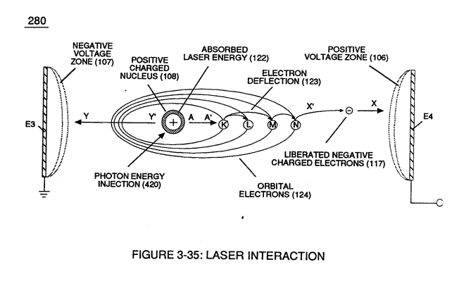
Figure (6-2)
Figure (6-2)
How it is written
- (6-2) 41×
Drawings 4
-
(57) of Figure (6-2) · In Application of Usage
-
Activation Process (590) of Figure (6-2) · Voltage Intensifier Coil-Assembly
-
(590) of Figure (6-2) · Capacitance (Cd)
-
(E9/10) of Figure (6-2) · Voltage Amplitude Switch-Off
On this figure 16
- 10 Led Pickup Circuit
- 16 Flame Projection
- 32 Analog Signal
- 57 Capacitor
- 66 Positive Voltage Potential
- 67 Opposite Polarity
- 85 Water Molecule
- 590 Taper Resonant Cavity
- 616 Water Gap
- E9 Capacitor
- E10 Capacitor
- RU Electrical Stress
- Re Water
- ST Electrical Stress
- Vn Voltage Potential
- Yo Resonant Voltage Intensity
Where it is named · 41
In Application of Usage 3×
-
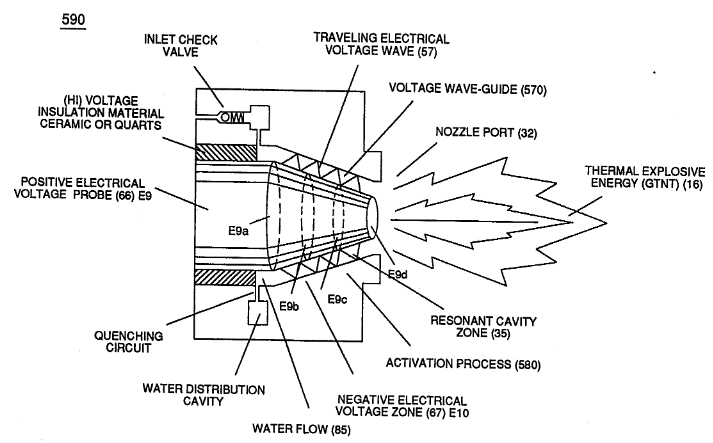
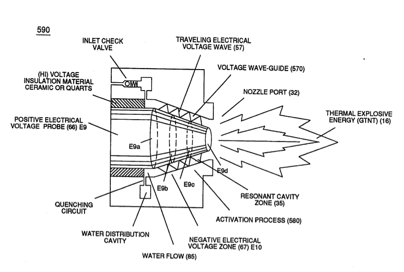
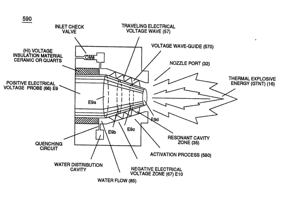
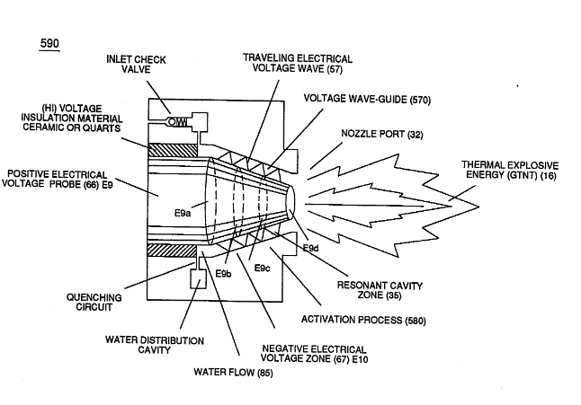
… lectron Extraction Process (230) of Figure (3-30) as to (270) of (3-34) ionizes the highly energized combustible gases to decrease atomic mass while applied traveling voltage wave-form (57) of Figure (6-2) of opposite electrical polarity (E9-66/ ElO-67) initiates the voltage-triggering process (600) of Figure (6-3) once maximum voltage deflection (VO - Va - Vb - Vc - Vn) of Figure (6-4) is achieved at Activation-Point (E9d) of Figure (6-2) ... …
-
… (E9-66/ ElO-67) initiates the voltage-triggering process (600) of Figure (6-3) once maximum voltage deflection (VO - Va - Vb - Vc - Vn) of Figure (6-4) is achieved at Activation-Point (E9d) of Figure (6-2) ... releasing thermal Explosive Energy (gtnt) from the atomic level of the water molecule.
-
(57) of Figure (6-2)
Water Fuel Injector 1×
-
… omic Energy Balance of Water" is further enhanced by simply electrically interfacing voltage intensifier (VIC) circuit coil-assembly (580) of Figure (6-1) with 'Taper Resonant Cavity" (590) of Figure (6-2), as schematically illustrated in (60) of Figure (3-22) as to pulse core configuration (190) of Figure (3-23) (Memo WFC 422 DA) titled "WFC Hydrogen Gas Management System.
Voltage Intensifier Coil-Assembly 2×
-
Activation Process (590) of Figure (6-2)
Instant Explosion of Water 2×
-
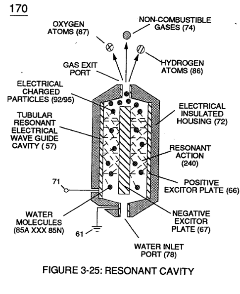
… ging during signal propagation) as elevated voltage levels ( - xx Vc- xx Vd - xx Vn) while allowing the reduction of Capacitor-Gap (Cp) (616) of Figure (7-11) width spacing (57 of Figure 3- 25 ~35 of Figure 6-2) (typically .060 - .010) respectively as illustrated in Tubular Resonant Cavity (170) as to Taper Resonant Cavity (620) of Figure (7-1).
-
(57 of Figure 3- 25 ~35 of Figure 6-2)
Resistance (Rs) 3×
-
Figure (590 & 57) of Figure (6-2)
Inductance (FL) 3×
-
… itor (E9/E10) of figure (6-2) as to (720) of Figure (7-11) is formed when outer tapered surface (66) and inner tapered surface (67) forms Water-Gap (616) of Figure (7-11) as to Figure (590) of Figure (6-2) having placed there between Dielectric Water Bath (85/Re), as schematically illustrated in matrix outline in (670) of Figure (7-6) as to (690) of Figure (7-8) and further detailed in Electrical Charg …
-
(E9/E10 & 590) of figure (6-2)
Capacitance (Cd) 4×
-
Capacitor (E9/E10) of Figure (7-1) as to Figure (650) of Figure (7-4) in direct relationship to Water Gap (616) becomes Taper Resonant Cavity (720) of Figure (7-11) as shown in (590) of Figure (6-2) since Water Gap (616) is occupied by a dielectric liquid (Re) as herein before identified as natural water (85) having no electrolyte added thereto
-
(590) of Figure (6-2)
-
(590) of Figure (6-2)
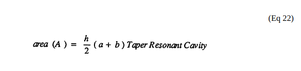
Taper Resonant Capacitor (ERt) 2×
-
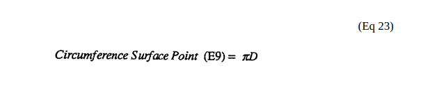
(a) being exit pan circumference surface point (E9d) of Figure (6-2),
-
(b) being cylindrical circumference surface point (E9a) of Figure (6-2) where tapered surface starts,
Capacitance Reactance 2×
-
Capacitor (ER) should remain relatively small due to the dielectric value of water to obtain maximum Thermal Explosive Energy-Yield (16a xxx 16n) of Figure (4-5) and subsequently establishing Quenching Circuit (370) of Figure (3-40) to prevent gas ignition inside traveling voltage wave-guide (590) of Figure (6-2) as to (730) of Figure (7-12)
-
(590) of Figure (6-2)
Electron Bounce Phenomenon 5×
-
Taper Resonant Cavity (590) of Figure (6-2)
-
(590) of Figure (6-2)
-
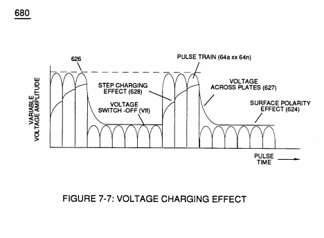
Of course, in practical terms of component interaction, a minute amount of amp leakage is present and does occur due to Electronic Component Limitations but is negligible as to the overall performance of the Hydrogen Fracturing Process (590) of Figure (6-2) when being subjected to either one of Traveling Electrical Voltage Wave-forms (730 a-b-c) of Figure (7-12), see Voltage Graph (750) of Figure (7-14) once again.
Voltage Amplitude Switch-Off 3×
-
Voltage levels of variance (Va xxx Vn) is achieved by simply switching-in or switching-out the member of Secondary Coil-cavities (505a xx 505n) (see 740 of Figure 7-13) in direct relationship to Taper Resonant Voltage surfaces (E9/10) of Figure (6-2) which acts and performs as a "Voltage Amplifier" when Compressional Wave-form (B) of Figure (7-12) is intensified at Exit Port (32) of Figure (6-2).
-
Voltage levels of variance (Va xxx Vn) is achieved by simply switching-in or switching-out the member of Secondary Coil-cavities (505a xx 505n) (see 740 of Figure 7-13) in direct relationship to Taper Resonant Voltage surfaces (E9/10) of Figure (6-2) which acts and performs as a "Voltage Amplifier" when Compressional Wave-form (B) of Figure (7-12) is intensified at Exit Port (32) of Figure (6-2).
-
(E9/10) of Figure (6-2)
8-2 - Traveling Voltage Wave-Guides 6×
-
(590) of Figure (6-2)
-
… potential (T1a xxxT1n) as to (Vo -64a-64b -64c - Vn) of (780A) Figure (8-2) to be applied across cross-sectional circular-ring water bath (85) (donut shape) to cause Voltage Wave-Form (57) of Figure (6-2) to travel the entire longitudinal length of water-gap (616) since stainless steel material (s/s) (T304) forming Voltage surfaces (E9/E1O) electrically conducts and transfers (skin effect) Voltage Pul …
-
(57) of Figure (6-2)
-
Voltage Intensifier Matrix Circuit (690) of Figure (7-8) electrically connected with resistive liquid (85/Re) (forming Resonant Water Gap "Cp" of Figure 7-8) propagates the transmission of Traveling Voltage Wave-Form (57) of Figure (6-2) as to (770) of Figure(8-1) by the functional relationship of Circuit Resistance Equation (Eq 9) during programmable Voltage Pulsing operations (49a xxx 1'3 xxx 49n) of Figure (8-2).
-
(57) of Figure (6-2)
8-7 - Application of Usage 2×
-
(590) of Figure (6-2)
WFC Development Objectives 2×
-
The primary Purpose/objective of Water Fuel Injection System (590) of Figure (6-2) as to "FullSystem" development (10) of Figure (4-1) is, in the realm of scientific quest, to help reverse the damage being done to "Earth Ecological Life Support System" by first of all encouraging the use of "Water" as a new "Fuel" source
-
Water Fuel Injection System (590) of Figure (6-2)
Voltage to Amp Differential Ratio 1×
-
The greater the Electrical Stress (RU-RU' a xxx ST -ST'n) applied (64B+/64B-a xxx 64B+/64B-), the greater amount of thermal explosive energy (16/gtnta xxx 16/gtntn) of Figure (6-2) as to (70) of Figure (4-5) is released from Resonant Water Gap (Cp) (970) of Figure (10-1), as further illustrated in (70) of Figure (4-5).