(170)
Resonant Cavity
Also written liquid resonant cavity · Tubular Resonant Cavity · Resonant Capacitor · Fluid Displacement Pump · Resonant Action · resonant cavity assembly · Resonant Cavities · water pump
Where it is first named
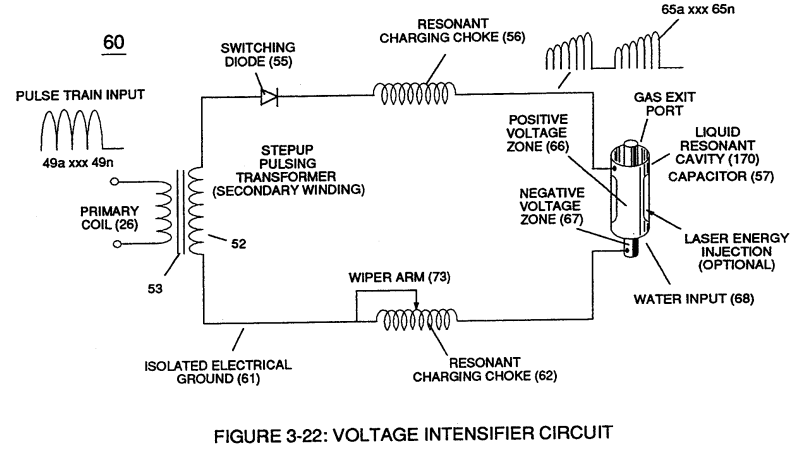
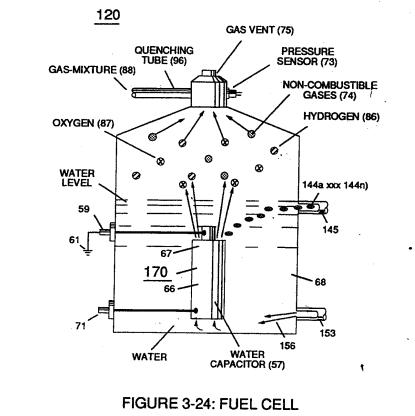
These controlled and variable pulse features are, now, translated to Resonant Charging pulse train (65a xxx 65n) of Figure (3-21) via Unipolar pulse train (64a xxx 64n) of Figure (3-20) during Resonant Action (160) of Figure (3-26) when signal coupling is applied across Resonant Cavity (170) of Figure (3-24) via positive voltage zone (66).
How it is written
- (170) 21×
- (140 -170) 5× with (140) Resonant Capacitor
- (140 - 170) 1× with (140) Resonant Capacitor
Drawings 92
-
Carries this number · Analog Voltage generator (40)
-
Figure (3-22) · Analog Voltage generator (40)
-
Figure (3-22) · Voltage Amplitude Control Circuit (50)
-
Figure (3-24) · Voltage Amplitude Control Circuit (50)
-
Figure (3-25) · Voltage Intensifier Circuit (60)
-
Figure (3-22) · Voltage Intensifier Circuit (60)
-
Figure (3-22) · Voltage Dynamics
-
Figure (3-24) · Electrical Polarization process
-
Voltage Intensifier Circuit (60) of Figure (3-22) · Gas Processor
-
reciprocating WFC Fuel-kits can be similar to Car design (340); · Aviation Application
-
Water Fuel Injector Plug (40) of Figure (4-2) · Operational Parameters
-
Carries this number · WFC 422DA - Illustrations
-
Carries this number · WFC 422DA - Illustrations
-
Carries this number · WFC 422DA - Illustrations
-
Carries this number · Water Fuel Injection System
-
Water Fuel Injection System (10) of Figure (1) · Water Fuel Injector (Taper Resonant Cavity Chamber)
-
(170) of Figure (13) · Water Fuel Injector (Taper Resonant Cavity Chamber)
-
(170) of Figure (13) · Water Fuel Injector (Taper Resonant Cavity Chamber)
-
Fluid Displacement Pump (170) of Figure (13) · Water Fuel Injector (Taper Resonant Cavity Chamber)
-
(650) of Figure (7-4) · Amp Inhibiting Circuit Vs Voltage Enhancement
-
Carries this number · Cover Page
-
Figure (4-2) · Water Fuel Injection System - Page 1
-
Figure (4-1) · Water Fuel Injection System - Page 1
-
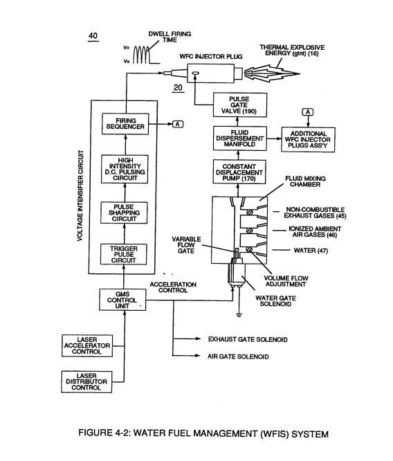
which simply uses Water Fuel Management (WFMS) System fluid-metering system (40) to control gas ignition (16), as illustrated in (40) of Figure (4-2). · Water Fuel Injection System - Page 4
-
Carries this number · Energy Pumping Action
-
Carries this number · VIC Matrix Circuit
-
Voltage Intensifier Circuit (60) of Figure (3-22) · Instant Explosion of Water
-
(56/62) of Figure (3-22) · Instant Explosion of Water
-
(57 of Figure 3- 25 ~35 of Figure 6-2) · Instant Explosion of Water
-
(T2) of Figure (7-8) · Instant Explosion of Water
-
(56) of Figure (3-22) · Instant Explosion of Water
-
Figure (7-8) · Resistance (Rs)
-
(650) of Figure (7-4) · Resistance (Rs)
-
(690) of Figure (7-8) · Resistance (Rs)
-
(630) of Figure (7-2) · Inductance (FL)
-
Carries this number · Inductance (FL)
-
(670) of Figure (7-6) · Inductance (FL)
-
(690) of Figure (7-8) · Inductance (FL)
-
LC circuit of Figure (7-2) · Inductance (FL)
-
(650) of Figure (7-4) · Inductance (FL)
-
Figure (3-24) · Inductance (FL)
-
(650) of Figure (7-4) · Capacitance (Cd)
-
(670) of Figure (7-6) · Capacitance (Cd)
-
(670) of Figure (7-6) · Capacitance (Cd)
-
(690) of Figure (7-8) · Capacitance (Cd)
-
(690) of Figure (7-8) · Inductance Reactance (Rs - Cd - FL)
-
Figure (7-8) · Inductance Reactance (Rs - Cd - FL)
-
Carries this number · Taper Resonant Capacitor (ERt)
-
(690) of Figure (7-8) · Taper Resonant Capacitor (ERt)
-
Resonant Capacitor (140 -170) of Figure (7-6) · Capacitance Reactance
-
Capacitor (ER) of Figure (7-2) · Capacitance Reactance
-
"Voltage Deflection" of Figure (7-4) · Capacitance Reactance
-
690 of Figure 7-8 · Circuit Resistance
-
Resonant Voltage Effect (670) of Figure (7-6) · Transformer Action
-
Opposite Electrical Attraction Force (SS' ~ 617 ~ RR' - T3 - SS' ~ 617 - RR') of Figure (7-4) · Electron Bounce Phenomenon
-
(52) of Figure (7-8) · Electron Bounce Phenomenon
-
Carries this number · WFC 426 - Illustrations
-
Carries this number · WFC 426 - Illustrations
-
Carries this number · WFC 426 - Illustrations
-
Carries this number · 8-2 - Traveling Voltage Wave-Guides
-
(690) of Figure (7-8) · 8-2 - Traveling Voltage Wave-Guides
-
(52) of Figure (7-8) · 8-3 - Electrical Voltage-Pulse Wave-Transmission
-
(Cp) of Figure (7-8) · 8-4 - State Space (Sp)
-
(650) of Figure (7-4) · 8-4 - State Space (Sp)
-
(170) of Figure (3-25) · 8-4 - State Space (Sp)
-
(40) of Figure (4-2) · 8-5 - Energy Vectoring (Ev)
-
(690) of Figure (7-8) · 8-6 - VIC Voltage Sync-Pulse Circuit
-
(650) of Figure (7-4) · 8-6 - VIC Voltage Sync-Pulse Circuit
-
(Cp) of (7-8) · 8-6 - VIC Voltage Sync-Pulse Circuit
-
"FullSystem" development (10) of Figure (4-1) · WFC Development Objectives
-
Carries this number · WFC Development Objectives
-
(690) of Figure (7-8) · Propagating Electrical Stress
-
Voltage Intensifier Circuit (60) of Figure (3-22) · Propagating Electrical Stress
-
Carries this number · Propagating Electrical Stress
-
(60) of Figure (3-22) · Propagating Electrical Stress
-
Fuel Cell (120) of Figure (3-24) · Operational Parameters
-
Voltage Intensifier Circuit (620) of Figure (7-1) · Instant Explosion of Water
-
(628) of Figure (7-7) · Instant Explosion of Water
-
(620) of Figure (7-1) · Instant Explosion of Water
-
(620) of Figure (7-1) · Resistance (Rs)
-
(614) of Figure (7-1) · Inductance (FL)
-
Inductor (614) of Figure (7-1) · Inductance (FL)
-
(614) of (7-1) · Inductance (FL)
-
Figure (7-1) · Capacitance (Cd)
-
(627) of Figure (7-7) · Inductance Reactance (Rs - Cd - FL)
-
(620) of Figure (7-1) · Inductance Reactance (Rs - Cd - FL)
-
Choke-Coil (62) of Figure (7-1) · Transformer Action
-
The figure it sits on · WFC 426 - Illustrations
-
The figure it sits on · WFC 426 - Illustrations
-
(620) of Figure (7-1) · 8-6 - VIC Voltage Sync-Pulse Circuit
-
"Resonant Charging Choke" (56) of Figure (7-1) · Propagating Electrical Stress
-
(620) of figure (7-1) · Voltage to Amp Differential Ratio
Where it is named · 27
Voltage Intensifier Circuit (60) 3×
-
Resonant Cavity (170)
These controlled and variable pulse features are, now, translated to Resonant Charging pulse train (65a xxx 65n) of Figure (3-21) via Unipolar pulse train (64a xxx 64n) of Figure (3-20) during Resonant Action (160) of Figure (3-26) when signal coupling is applied across Resonant Cavity (170) of Figure (3-24) via positive voltage zone (66).
-
resonant cavity assembly (170)
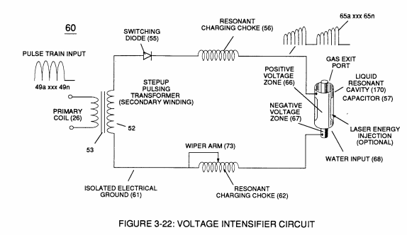
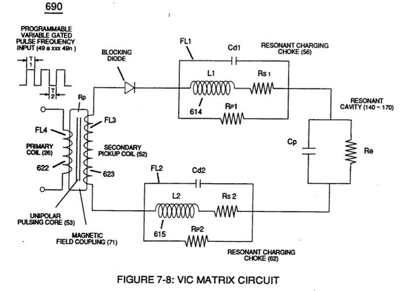
The resultant signal coupling ( 65a xx 65n ) of Figure (3-21) is accomplished since primary coil (26), pulsing core (53), secondary coil (52), switching diode (55), resonant charging choke (56), resonant cavity assembly (170), natural water (68), and variable resonant charging choke (62) forms Voltage Intensifier Circuit (60) of Figure (3-22), as illustrated in Figure (3-22) as to Figure (3-23).
-
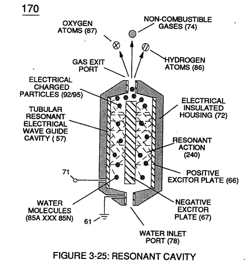
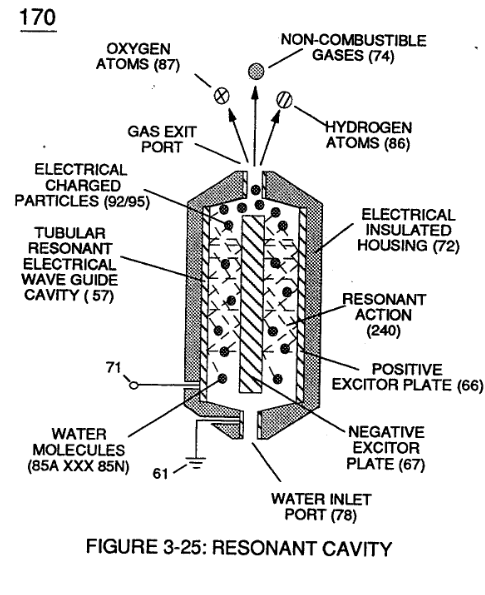
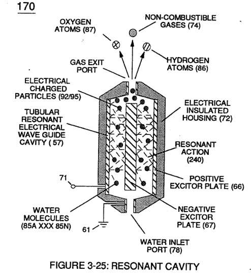
forms capacitor (57), as illustrated in (170) of Figure (3-25).
Resonant Action 3×
-
Applied together, electrical forces (TT') and (UU'), now, causes these moving electrically charged particles to superimpose a physical impact unto electrical polarization process (160), as shown in (170) of Figure (3-25)
-
resonant cavity (170)
To reach maximum gas-yield (88) resonant cavity (170) of Figure (3-25) is shaped into a tubular structure (typically 0.50 inch diameter tube inserted into 0.75 inch diameter tube having a .0625 concentric air-gap 3 inches long) which functions as a longitudinal wave-guide to enhance particle movement in a lateral or angular displacement to applied voltage fields (66/67).
-
resonant cavity (170)
In practice, stainless steel voltage plates (E1/E2) physically forms voltage zones (66/67) regardless of geometric shape or configuration of resonant cavity (170).
Gas Processor 2×
-
liquid resonant cavity (170)
Voltage fields (106/107) are physically configured (skin effect) by T304 stainless steel material to form voltage plates (E3/E4) of Figure (3-33) which are not only chemically inert to gas ionization process (260) but, also, forms tubular Gas Resonant Cavity (410) of Figure (3-34) having approximately the same size and shape of liquid resonant cavity (170) of Figure (3-25), as illustrated in (270) of Figure (3-34).
-
liquid resonant cavity (170)
liquid resonant cavity (170) of Figure (3-25)
Impurity Extraction Process 2×
-
Resonant Action (170)
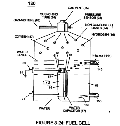
Suspended and dissolved water contaminates (144a xxx 144n) (typically 20 ppm to 40 ppm in natural water) of Figure (3-24) being uniformly released from and superimposed onto remaining water bath (68) during Resonant Action (170) are directed to and passes through water inlet line (145)
-
Resonant Action (170)
... producing purified water bath (156) which is recycled back into Fuel Cell (120) of Figure (3-24) since Resonant Action (170) also function as and performs as a water-pump (Gas rising).
Water Fuel Injection System 1×
-
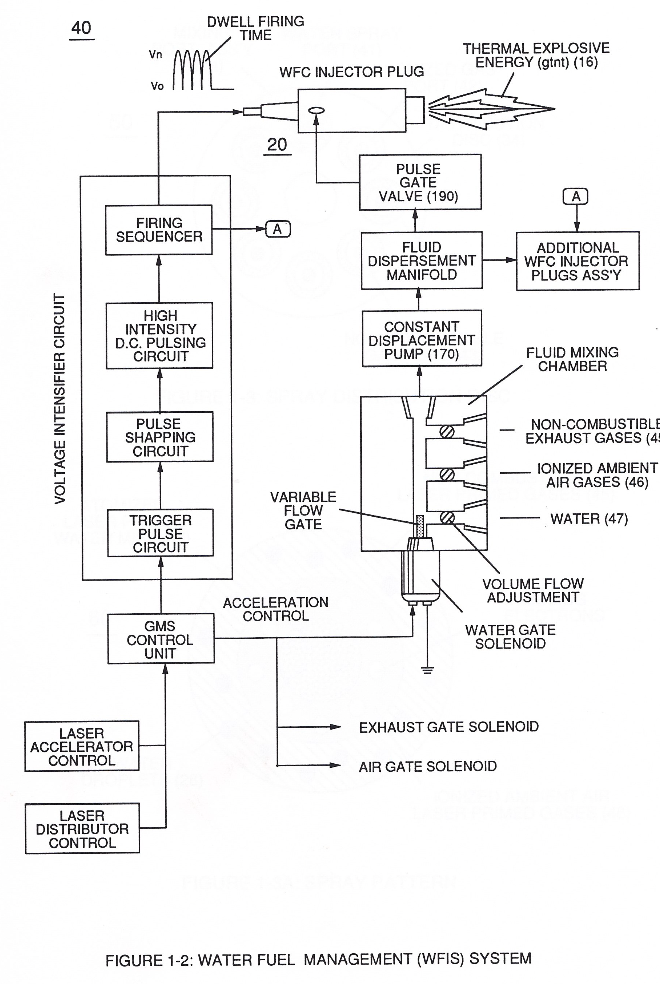
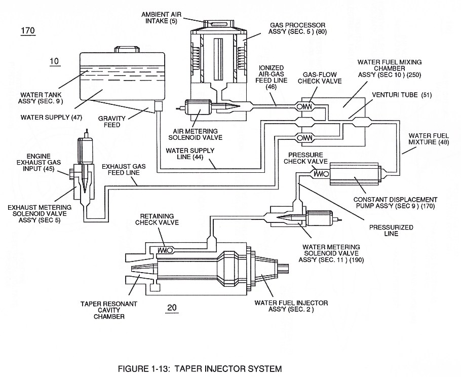
To ensure proper energy-flame projection and subsequent energy-flame stability, constant placement water pump (170) causes and allows ionized ambient air gases (46), non-combustible gases (45), and water (47) to be displaced under static pressure up to and beyond 125 psi respectively.
Water Fuel Injector (Taper Resonant Cavity Chamber) 5×
-
releasing thermal explosive energy (gtnt) via flame projection (16) of Figure (3B) as to Figure (14), Water Fuel Injection System (10) of Figure (1) as to (170) of Figure (13) incorporates and uses Taper Resonant Cavity Chamber (180) of Figure (14) to enhance operational parameters of Hydrogen Fracturing Process (100) of Figure (6) being stimulated to activa …
-
(170) of Figure (13)
-
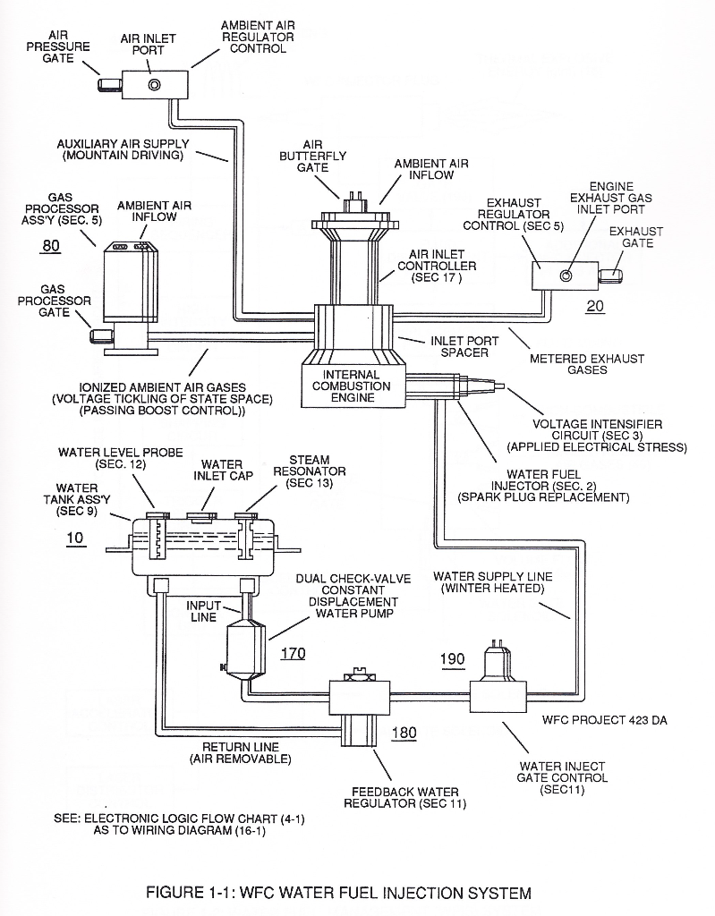
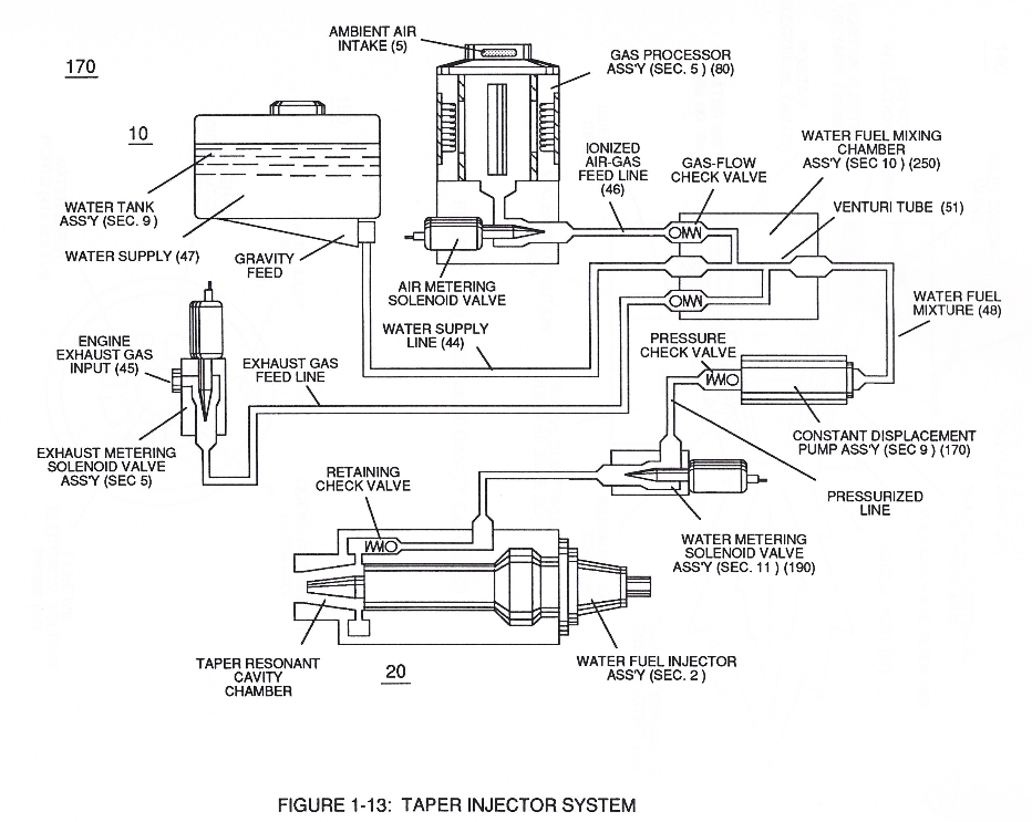
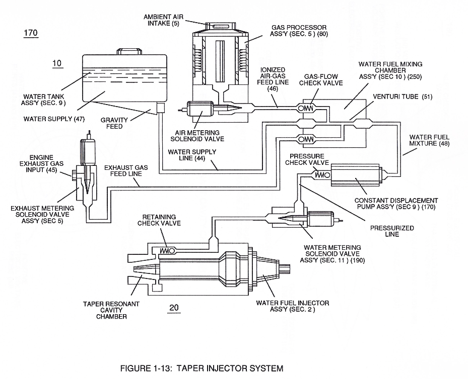
In like manner, water supply (10) of Figure (170), non-combustible gases (45) (Engine Exhaust gases), and ambient air ionized gases (46) (air gases having missing electrons) are uniformly intermixed when moving into, passing through and beyond fluid mixing chamber (250) of Figure (13) by way of venturi tube-cavity (51)...
-
Fluid Displacement Pump (170)
The resultant water fuel-mixture (48) is, now, pressurized up to and beyond 125 lbs of fluid-pressure by Fluid Displacement Pump (170) of Figure (13), as before, to cause and form water fuel-droplets (48a xxx 48n) when water fuel (48) enters into, passes through and beyond spray ports (41a xxx 41n) forming Quenching Disc Structure (190) of Figure (15).
Water Fuel Injection System - Page 2 1×
-
water pump (170)
To ensure proper energy-flame projection and subsequent energy-flame stability, constant displacement water pump (170) causes and allows ionized ambient air gases (46), noncombustible gases (45), and water (47) to be displaced under static pressure up to and beyond 125 lbs psi, respectively.
Instant Explosion of Water 2×
-
Resonant Cavity (140 - 170)
… de (55) to encourage and make use of "Electron Bounce" phenomena (700) of Figure (7-9) to help promote Step Charging Effect (628) of Figure (7-7) by preventing electrical discharge of Resonant Cavity (140 - 170) since Blocking Diode functions as an "Open" switch during Pulse Off-time;
-
Tubular Resonant Cavity (170)
… allowing the reduction of Capacitor-Gap (Cp) (616) of Figure (7-11) width spacing (57 of Figure 3- 25 ~35 of Figure 6-2) (typically .060 - .010) respectively as illustrated in Tubular Resonant Cavity (170) as to Taper Resonant Cavity (620) of Figure (7-1).
Inductance Reactance (Rs - Cd - FL) 2×
-
Resonant Cavity (140 -170)
… riction (Rp1/Rp2) to both Inductor Chokes (56/62) but automatically increases voltage potential (xxx V g xxx Vh xxx Vn) of opposite voltage intensity of equal magnitude (66/67) across Resonant Cavity (140 -170)
-
Resonant Cavities (140 -170)
… -1) as to (620) of Figure (7-1) without amp "influxing" (inhibiting amp flow) between Positive Voltage Potential (66) and Negative Voltage Potential (67) electrically applied across Resonant Cavities (140 -170).
In-Line Circuit Components 1×
-
Resonant Capacitor (140 -170)
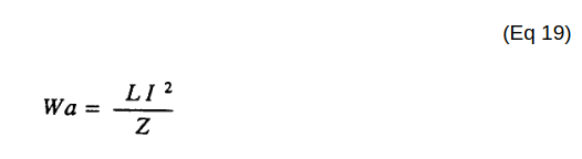
Lengthening Inductor (L1/L2) lengths applies an even higher Voltage Potential (66/67) across Resonant Capacitor (140 -170) (ER) since Inductance Reactance "Stores" Energy and, is expressed by:
Capacitance Reactance 2×
-
Resonant Capacitor (140 -170)
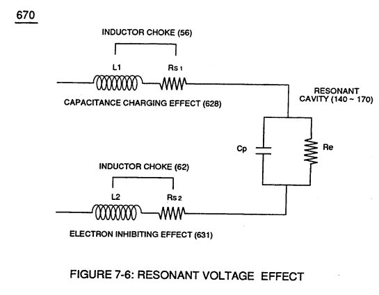
Plate Inductance (Lc) is Inductance Reactance of Inductor (L1 ) and Inductance Reactance of Inductor (L2) in series with Resonant Capacitor (140 -170) of Figure (7-6) as to (690) of Figure (7-8).
-
Resonant Capacitor (140 -170)
Resonant Capacitor (140 -170) of Figure (7-6)
8-4 - State Space (Sp) 2×
-
Resonant Cavity (170)
Voltage Tickling of State Space under "Resonant Electrical Stress" without amp influxing while ''Tuning-In' to the dielectric properties of water is herein referred to in this WFC Tech-manual as "Resonant Action," as illustrated graphically in Figure (5-4 A,B,C) as to Resonant Cavity (170) of Figure (3-25) as to Figure (1-13).
-
(170) of Figure (3-25)
VIC Switchover Circuit 1×
-
In like manner as to linear cylindrical resonant cavity (730) of Figure (7-12), the Differential Voltage Wave-Guide (1040) of (1010) of Figure (11-1) as to Figure (11-6) is constructed in such a way as to allow a smaller tube to be placed inside a much larger tube having space relationship to allow water to pass there between, as so pictorially shown in (170) of Figure (3-25).