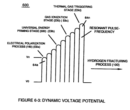
Figure (6-3)
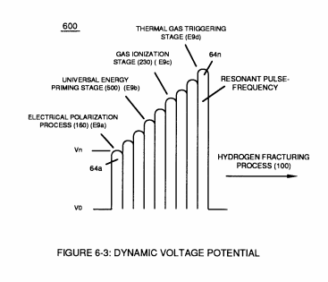
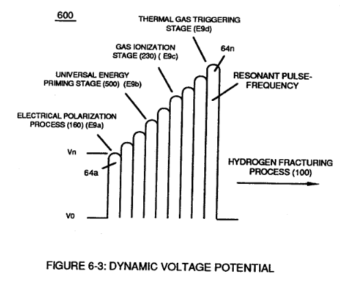
Dynamic Voltage Potential
How it is written
- (6-3) 14×
Drawings 5
-
"Voltage Intensity of Opposite Potential" (600) of Figure (6-3) · Voltage Intensifier Coil-Assembly
-
Captioned as this figure · WFC 425 - Illustrations
-
(600) of Figure (6-3) · Inductance (FL)
-
(600) of Figure (6-3) · Inductance (FL)
-
Captioned as this figure · 8-1 - Propagating "Resonant Action" By Voltage Tickling of State Space
On this figure 11
- 49 Voltage Pulse frequency
- 66 Positive Voltage Potential
- 67 Opposite Polarity
- 600 Dynamic Voltage Potential
- E1 Voltage Zones
- E2 Voltage Zones
- E9 Capacitor
- E10 Capacitor
- ElO —
- T3 Unipolar Pulse-Train
- Vn Voltage Potential
Where it is named · 14
In Application of Usage 1×
-
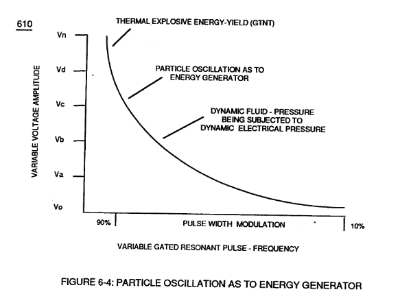
… e gases to decrease atomic mass while applied traveling voltage wave-form (57) of Figure (6-2) of opposite electrical polarity (E9-66/ ElO-67) initiates the voltage-triggering process (600) of Figure (6-3) once maximum voltage deflection (VO - Va - Vb - Vc - Vn) of Figure (6-4) is achieved at Activation-Point (E9d) of Figure (6-2) ... …
Water Fuel Injector 1×
-
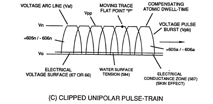
At each progressive point of diminishing circumference surface-area (E9a - b - c - d - E9n) voltage amplitude intensity increases (Vna - b - c - d - Vnn) uniformly, as illustrated in (600) of Figure (6-3) as to Travelling Voltage Wave-forms (730a - b - c) of Figure (7-12), see WFC Memo (426).
Voltage Intensifier Coil-Assembly 2×
-
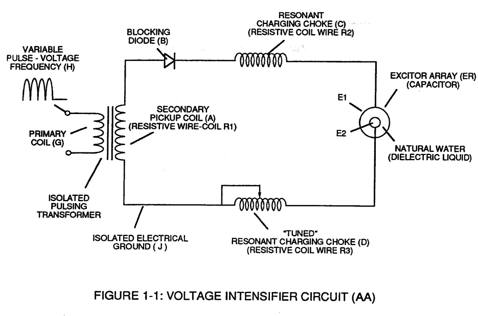
Inherently, the design parameters of coil-structures (580) of Figure (6-1) determines "Efficiency" (minimizing amp leakage) by which "Voltage Intensity of Opposite Potential" (600) of Figure (6-3) can perform work to trigger Hydrogen Fracturing Process (520) of Figure (5-3) (Memo WFC 424 DA) as to (100) of Figure (4-8) (Memo WFC 423DA), as graphically denoted in (750) of Figure (7-14) of WFC m …
-
"Voltage Intensity of Opposite Potential" (600) of Figure (6-3)
Inductance (FL) 4×
-
Component Interaction promotes Component Reactance during D.C. pulsing operations while allowing variable voltage amplitude (Vo - Va -Vb - Vn) of Figure (7-13) to be attenuated independently of Voltage Pulse frequency (49a xxx 49n), as so illustrated in (600) of Figure (6-3).
-
(600) of Figure (6-3)
-
… harging Choke (614) which steps up an unipolar oscillation of an given charging frequency with the effective capacitance of a pulse-forming network (64a xxx 64n) of Figure (7-1) as to (600) of Figure (6-3) in order to charge Voltage Zones (E9/E10) to a higher potential beyond applied voltage input
-
(600) of Figure (6-3)
Taper Resonant Capacitor (ERt) 1×
Capacitance Reactance 2×
-
(600) of Figure (6-3)
Electron Bounce Phenomenon 1×
-
... producing Dynamic Voltage Potential (600) of Figure (6-3) during repetitive pulsing (49a xxx 49n - T3 - 49a xxx 49n)

8-1 - Propagating "Resonant Action" By Voltage Tickling of State Space 1×
-
… nging or altering the physical configuration of the "Voltage Wave-guides" (Resonant Cavity structure of design) in direct reference to applied ever changing Unipolar Voltage Amplitude Pulse-Wave (see Figure 6-3 of WFC memo 425) to bring-on and propagate a predetermine flame-density of projection by pre-selecting the "State Space" in which the injected and incoming water bath is subjected to performing work of instantly converting water into thermal explosive energy (gtnt) on demand... …
8-4 - State Space (Sp) 1×
-
… a “Energy Generator" (EGpo), as so subscribed in memo (424) titled Atomic Energy Balance of Water as to the functional parameters associated with Dynamic Voltage Potential Wave-form (600) of Figure (6-3) which uses Voltage Pulse Potential of opposite electrical polarity of attraction (RR' - SS' as to RU/RU' – ST/DST') to perform work in the following sequence of events in an instant of time: Electr …