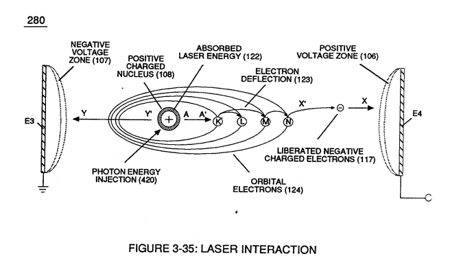
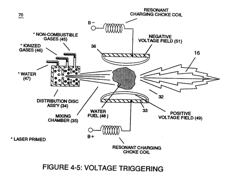
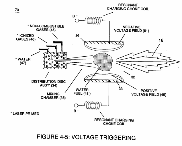
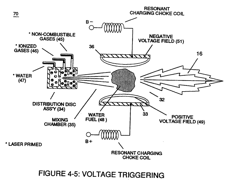
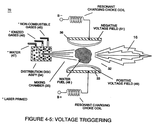
Figure (4-5)
Voltage Triggering
Also written Constrictor Zone High Energy Input Pulse-zone Linear State Space · Resonant Pulse - Frequency Inject Circuit S
How it is written
- (4-5) 32×
Drawings 9
-
Captioned as this figure · Electronic Circuit Design
-
Figure (4-5) · Water Fuel Injection System - Page 1
-
but, also prevents electron flow into destabilizing gas process (180), as so illustrated in Figure (4-5). · Water Fuel Injection System - Page 3
-
Captioned as this figure · In Application of Usage
-
Voltage Triggering Process (70) of Figure (4-5) · Voltage Intensifier Coil-Assembly
-
(16) of Figure (4-5) · Resistance (Rs)
-
Figure (4-5) · Capacitance Reactance
-
Figure (4-5) · 8-5 - Energy Vectoring (Ev)
-
Captioned as this figure · WFC 427 Illustrations
On this figure 19
- 16 Flame Projection
- 29 Battery Voltage Potential
- 32 Analog Signal
- 33 Applied Voltage Intensity
- 34 Gas Mixing Disc
- 35 Resonant Cavity Zone
- 36 Fuel Injectors
- 45 Non-Combustible Gases
- 46 Ionized Ambient Air Gases
- 47 Water Mist
- 48 Water-fuel mixture
- 49 Voltage Pulse frequency
- 51 Opposite Electrical Voltage Fields
- 70 Voltage Triggering Process
- 180 Voltage Igniter Stage
- E7 —
- E8 —
- ER Excitor-Array
- Fy Physical Force-Yield
Where it is named · 32
Water Fuel Injection System - Page 1 8×
-
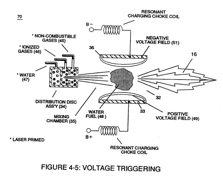
First water mist (47) of Figure (4-4) is injected into fuel-mixing chamber (35) of Figure (4-5) by way of water spray ports (41a xxx 41n) of Figure (4-4);
-
Figure (4-5)
-
Secondly, ionized air gases (46a xxx 46n) of Figure (4-4) (laser primed ambient air gases having missing electrons) produced by Ambient Air Ionizer (80) of Figure (4-6) as to Figure (4-1) and non-combustible gases (45) of Figure (4-4) are intermixed with expelling water mist (47a xxx 47n) to form Water-fuel mixture (48) by way of gas mixing disc (34) of Figure (4-5) as to (30) of Figure (4-2);
-
Figure (4-5)
Water Fuel Injection System - Page 2 4×
-
... producing uniformed water-fuel mixture (48), as illustrated in Figure (4-5).
-
Energy-Flame temperature is regulated by controlling the volume flow-rate of each fluid-mediums (47 / 45 / 46) in direct relationship to applied voltage intensity (33 / 36), as further illustrated in Figure (4-2) as to Figure (4-5).
Water Fuel Injection System - Page 3 1×
-
but, also prevents electron flow into destabilizing gas process (180), as so illustrated in Figure (4-5).
In Application of Usage 1×
-
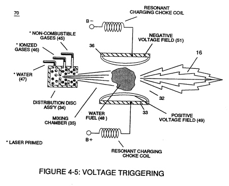
The Hydrogen Fracturing Process (390) of Figure (3-42) simply triggers and releases atomic energy (gtnt) from natural water (85) of Figure (3-26) by retarding and preventing the reformation of the water molecule being subjected to sub-critical state (520) of Figure (5-3) during thermal gas ignition (100) of Figure (4-8) as to (70) of Figure (4-5).
Taper Water Fuel Injectors 1×
Voltage Intensifier Coil-Assembly 2×
-
Voltage Triggering Process (70) of Figure (4-5)
Resistance (Rs) 2×
-
... releasing thermal explosive energy (gtnt) (16) of Figure (4-5) on demand from natural water (85) of Figure (3-26) since the dielectric value (Re) of (Eq.9) of Water Fuel (85) is further approximated in Capacitance Equation (Eq.22), as illustrated in (650) of Figure (7-4) as to Tapered Voltage Wave-Guide (720) of Figure (7-11)
-
(16) of Figure (4-5)
Capacitance Reactance 5×
-
Capacitor (ER) should remain relatively small due to the dielectric value of water to obtain maximum Thermal Explosive Energy-Yield (16a xxx 16n) of Figure (4-5) and subsequently establishing Quenching Circuit (370) of Figure (3-40) to prevent gas ignition inside traveling voltage wave-guide (590) of Figure (6-2) as to (730) of Figure (7-12)
-
which, when occurring at gas exit port (32) of Figure (4-5), spark-ignites expanding water gas-fuel (45/46/47) of Figure (4-5) during water inject cycle (70) of Figure (4-5)
-
which, when occurring at gas exit port (32) of Figure (4-5), spark-ignites expanding water gas-fuel (45/46/47) of Figure (4-5) during water inject cycle (70) of Figure (4-5)
-
which, when occurring at gas exit port (32) of Figure (4-5), spark-ignites expanding water gas-fuel (45/46/47) of Figure (4-5) during water inject cycle (70) of Figure (4-5)
-
Figure (4-5)
Electron Bounce Phenomenon 4×
-
(70) of Figure (4-5)
8-5 - Energy Vectoring (Ev) 2×
-
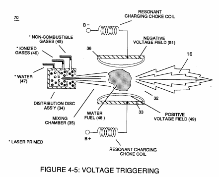
The "mode of operability" of determining the "Operational Parameters" of adjusting the thermal explosive energy (gtnt) exiting from nozzle-port (32) of Figure (4-5) as to (40) of Figure (4-2) is directly related to the characteristics of the applied Voltage Pulse Potential (Vpp) Wave-form (s) (Vpwt) and the geometrical configuration of Resonant Cavity (90) of Figure (4-7) as to (730) of Figure (7-12).
-
Figure (4-5)
Voltage to Amp Differential Ratio 2×
-
The greater the Electrical Stress (RU-RU' a xxx ST -ST'n) applied (64B+/64B-a xxx 64B+/64B-), the greater amount of thermal explosive energy (16/gtnta xxx 16/gtntn) of Figure (6-2) as to (70) of Figure (4-5) is released from Resonant Water Gap (Cp) (970) of Figure (10-1), as further illustrated in (70) of Figure (4-5).
-
The greater the Electrical Stress (RU-RU' a xxx ST -ST'n) applied (64B+/64B-a xxx 64B+/64B-), the greater amount of thermal explosive energy (16/gtnta xxx 16/gtntn) of Figure (6-2) as to (70) of Figure (4-5) is released from Resonant Water Gap (Cp) (970) of Figure (10-1), as further illustrated in (70) of Figure (4-5).