(57)
Capacitor
Also written Resonant Charging Chokes · Forming Resonant Charging Chokes · Traveling Voltage Wave-Form · Voltage Wave-Form · stainless steel induction coil · resonant cavity · inductor coils · excitor array and 1 more
Where it is first named
...allowing magnetic fields of both inductor coils (56/57) to collapse ... forming pulse train (64a xxx 64n).
How it is written
- (57) 16×
- (56/57) 7× with (56) Resonant Charging Choke
Drawings 52
-
Figure (3-22) · Analog Voltage generator (40)
-
Figure (3-22) · Voltage Amplitude Control Circuit (50)
-
Figure (3-24) · Voltage Amplitude Control Circuit (50)
-
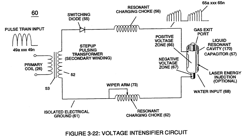
The impedance of inductor (56) and capacitor (57) in series, Z series is given by (Eq 1) · Voltage Intensifier Circuit (60)
-
Figure (3-25) · Voltage Intensifier Circuit (60)
-
Figure (3-22) · Voltage Intensifier Circuit (60)
-
Figure (3-22) · Voltage Dynamics
-
Figure (3-24) · Electrical Polarization process
-
Voltage Intensifier Circuit (60) of Figure (3-22) · Gas Processor
-
Carries this number · WFC 422DA - Illustrations
-
Carries this number · WFC 422DA - Illustrations
-
Carries this number · WFC 422DA - Illustrations
-
Carries this number · WFC 422DA - Illustrations
-
Carries this number · Funneling Effect
-
Figure (4-10) · Water Fuel Injection System - Page 2
-
Carries this number · Energy Pumping Action
-
(57) of Figure (6-2) · In Application of Usage
-
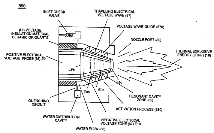
Activation Process (590) of Figure (6-2) · Voltage Intensifier Coil-Assembly
-
Voltage Intensifier Circuit (60) of Figure (3-22) · Instant Explosion of Water
-
(56/62) of Figure (3-22) · Instant Explosion of Water
-
(57 of Figure 3- 25 ~35 of Figure 6-2) · Instant Explosion of Water
-
(56) of Figure (3-22) · Instant Explosion of Water
-
Figure (3-24) · Inductance (FL)
-
(590) of Figure (6-2) · Capacitance (Cd)
-
(730) of Figure (7-12) · Taper Resonant Capacitor (ERt)
-
Traveling Electrical Voltage Wave-forms (730a - b - c) of Figure (7-12) · Electron Bounce Phenomenon
-
(E9/10) of Figure (6-2) · Voltage Amplitude Switch-Off
-
Compressional Wave-form (B) of Figure (7-12) · Voltage Amplitude Switch-Off
-
Carries this number · Mode of Operability
-
Carries this number · WFC 426 - Illustrations
-
(730A) of Figure (7-12) · 8-2 - Traveling Voltage Wave-Guides
-
(570) of Figure (7-12) · 8-2 - Traveling Voltage Wave-Guides
-
(170) of Figure (3-25) · 8-4 - State Space (Sp)
-
(730) of Figure (7-12) · 8-5 - Energy Vectoring (Ev)
-
(730C) of Figure (7-12) · 8-7 - Application of Usage
-
(730A) of Figure (7-12) · 8-7 - Application of Usage
-
Voltage Intensifier Circuit (60) of Figure (3-22) · Propagating Electrical Stress
-
(60) of Figure (3-22) · Propagating Electrical Stress
-
Figure (3-21) · Voltage Amplitude Control Circuit (50)
-
Figure (3-18) · Cell Driver Circuit (90)
-
Figure (3-19) · Cell Driver Circuit (90)
-
Figure (3-19) · Voltage Intensifier Circuit (60)
-
Figure (3-28) · Voltage Intensifier Circuit (60)
-
Ohm's law of LC circuit (180) of Figure (3-28) in series is given by (Eq 5) · Voltage Intensifier Circuit (60)
-
Voltage (Vc) of Figure (3-28) across the capacitor is given by (Eq 7) · Voltage Intensifier Circuit (60)
-
Figure (3-21) · Voltage Intensifier Circuit (60)
-
The figure it sits on · Voltage Dynamics
-
The figure it sits on · Gas Processor
-
The figure it sits on · WFC 422DA - Illustrations
-
The figure it sits on · WFC 422DA - Illustrations
-
The figure it sits on · WFC 422DA - Illustrations
-
The figure it sits on · 8-1 - Propagating "Resonant Action" By Voltage Tickling of State Space
Where it is named · 23
Voltage Intensifier Circuit (60) 10×
-
inductor coils (56/57)
...allowing magnetic fields of both inductor coils (56/57) to collapse ... forming pulse train (64a xxx 64n).
-
capacitor (57)
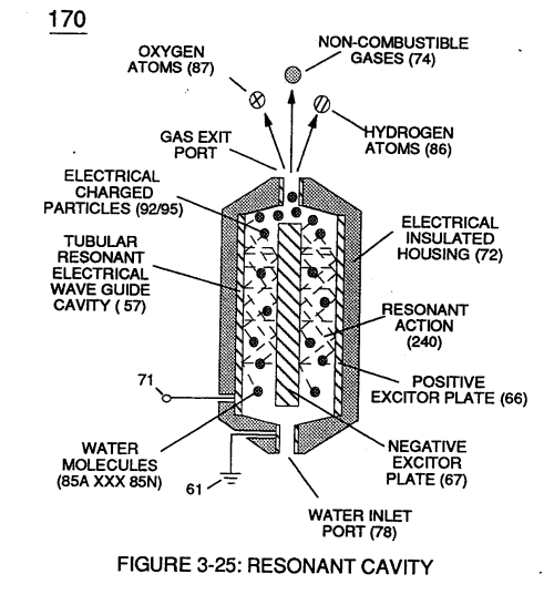
forms capacitor (57), as illustrated in (170) of Figure (3-25).
-
capacitor (57)
Inductor (56) and capacitor (57) properties of LC circuit (180) is therefore "tuned" to resonate at a given frequency.
-
capacitance (57)
Resonant frequency (63) of Figure (3-19) can be raised or lowered by changing the inductance (56) and/or capacitance (57) valves.
-
The value of inductor (56), value of capacitor (57), and the pulse-frequency (63) of voltage (Yo xxx Vn) being applied across the LC circuit determined the impedance of LC circuit (Figure 3-28).
-
capacitor (57)
The impedance of inductor (56) and capacitor (57) in series, Z series is given by (Eq 1)
-
capacitor (57)
The voltage across inductor (56) or capacitor (57) is greater than applied voltage (49) of Figure (3-18).
-
During resonant interaction, the incoming unipolar pulse train (64a xxx 64n) of Figure (320) as to Figure (3-21) produces a step charging voltage effect across excitor-array (66/67) (57) as so illustrated in Figure (3-21).
-
excitor array (57)
"Voltage intensity or level across excitor array (57) can exceed 20,000 volts due to circuit (60) interaction and is directly related to pulse train (64a xxx 64n) variable amplitude input.
-
resonant cavity (57)
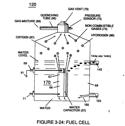
Amp leakage (electron coupling to water) to water bath (68) of Figure (3-24) is further prevented by encapsulating resonant cavity (57) in delrin material (72) of Figure (3-25) which is an electrical insulator to high voltage.

Water Fuel Injector (Taper Resonant Cavity Chamber) 6×
-
Resonant Charging Chokes (56/57)
... forming a capacitor (E7 / E8) in series with Resonant Charging Chokes (56/57) placed on opposite sides of Resonant Cavity Zone (35) as to Figure (7) and (8) . . . forming a Resonant Pulsing Circuit (110) of Figure (7) with step-up Pulsing Transformer (33/36), as shown in (220) of Figure (18).
-
Resonant Charging Chokes (56/57)
Sequential Switch Circuit (59) simply switches in and out Booster Pickup Coils (61a xxx 61n) in series electrical hookup with Secondary Coil (53) output to elevate voltage intensity across Resonant Charging Chokes (56/57).
-
Forming Resonant Charging Chokes (56/57)
Forming Resonant Charging Chokes (56/57) by using Stainless Steel Electro-Inductance wire-material (430F / T304 or equivalent) which, when electrically pulsed transmits voltage intensity while restricting amp flow during Resonant Pulsing operations. …
-
… Together, the resistive valve of Stainless Steel wire-coil (56/57) and its inductance generated electromagnetic field (62) of Figure (19) opposes the movement of electrons since the dielectric valve of wire-coils (56/57) inhibits electron exchange while the generate …
-
… Together, the resistive valve of Stainless Steel wire-coil (56/57) and its inductance generated electromagnetic field (62) of Figure (19) opposes the movement of electrons since the dielectric valve of wire-coils (56/57) inhibits electron exchange while the generated inductance field (62) locks onto the electromagnetic field of the electrons ...generated coil inductance field (62) being greater in electromagnetic... …
-
stainless steel induction coil (56/57)
In other words, the inductance and capacitance values of stainless steel induction coil (56/57) bypasses voltage drop across its resistive load (ohmic valve of wire).
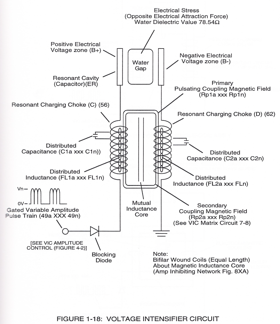
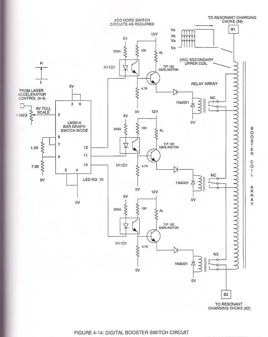
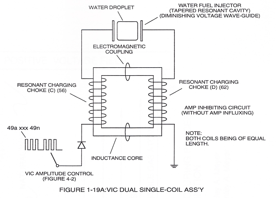
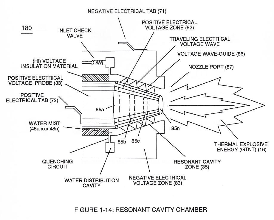
In Application of Usage 2×
-
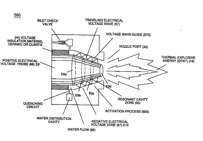
The Electron Extraction Process (230) of Figure (3-30) as to (270) of (3-34) ionizes the highly energized combustible gases to decrease atomic mass while applied traveling voltage wave-form (57) of Figure (6-2) of opposite electrical polarity (E9-66/ ElO-67) initiates the voltage-triggering process (600) of Figure (6-3) once maximum voltage deflection (VO - Va - Vb - Vc - Vn) of Figure (6-4) is achieved at Activation-Point (E9d) of Figure (6-2) ... …
-
(57) of Figure (6-2)
Resistance (Rs) 1×
-
while, at the same time, conducting and permitting the transmission of "Voltage Potential" across circumference surface area (skin effect) (66/67) of Figure (7-11) as to Figure (590) of Figure (6-2) to bring-on and perform Voltage Wave-Guide phenomena (57) of Figure (6-2)
8-2 - Traveling Voltage Wave-Guides 4×
-
Voltage Wave-Form (57)
… pulse-frequency potential (T1a xxxT1n) as to (Vo -64a-64b -64c - Vn) of (780A) Figure (8-2) to be applied across cross-sectional circular-ring water bath (85) (donut shape) to cause Voltage Wave-Form (57) of Figure (6-2) to travel the entire longitudinal length of water-gap (616) since stainless steel material (s/s) (T304) forming Voltage surfaces (E9/E1O) electrically conducts and transfers (skin eff …
-
(57) of Figure (6-2)
-
Traveling Voltage Wave-Form (57)
Voltage Intensifier Matrix Circuit (690) of Figure (7-8) electrically connected with resistive liquid (85/Re) (forming Resonant Water Gap "Cp" of Figure 7-8) propagates the transmission of Traveling Voltage Wave-Form (57) of Figure (6-2) as to (770) of Figure(8-1) by the functional relationship of Circuit Resistance Equation (Eq 9) during programmable Voltage Pulsing operations (49a xxx 1'3 xxx 49n) of Figure (8-2).
-
(57) of Figure (6-2)