(190)
Voltage Intensifier Circuit
Also written Quenching Disc Structure · Inductance Pulsing-Core · Pulse Gate Valve · interfacing voltage circuit · electrical circuit
Where it is first named
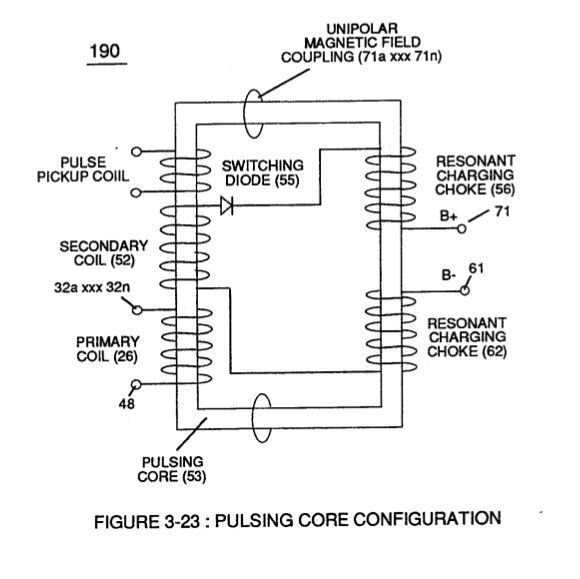
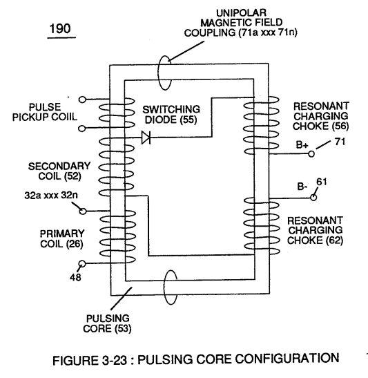
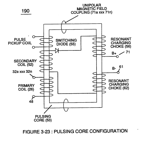
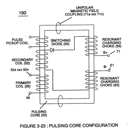
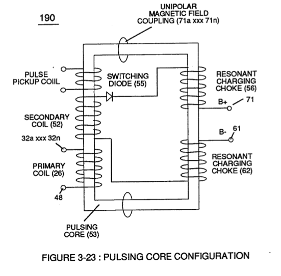
Inherently, then, pulsing core (53) of Figure (3-23) aids amp restriction while voltage intensifier circuit (190) is being "tuned" (adjusting pulse train 49a xxx 49n pulse-frequency 63 via pulse frequency generator 70 of figure 3-5) to match the resonant frequency properties of water bath (68) of Figure (3-22), as illustrated in Fuel Cell (120) of Figure (3-24).
How it is written
- (190) 16×
Drawings 35
-
Figure (3-23) · Voltage Intensifier Circuit (60)
-
Figure (3-23) · Voltage Dynamics
-
reciprocating WFC Fuel-kits can be similar to Car design (340); · Aviation Application
-
Water Fuel Injector Plug (40) of Figure (4-2) · Operational Parameters
-
Carries this number · WFC 422DA - Illustrations
-
Carries this number · Water Fuel Injection System
-
Water Fuel Injection System (10) of Figure (1) · Water Fuel Injector (Taper Resonant Cavity Chamber)
-
(170) of Figure (13) · Water Fuel Injector (Taper Resonant Cavity Chamber)
-
(170) of Figure (13) · Water Fuel Injector (Taper Resonant Cavity Chamber)
-
Fluid Displacement Pump (170) of Figure (13) · Water Fuel Injector (Taper Resonant Cavity Chamber)
-
Quenching Disc Structure (190) of Figure (15) · Water Fuel Injector (Taper Resonant Cavity Chamber)
-
Figure (4-2) · Water Fuel Injection System - Page 1
-
Figure (4-1) · Water Fuel Injection System - Page 1
-
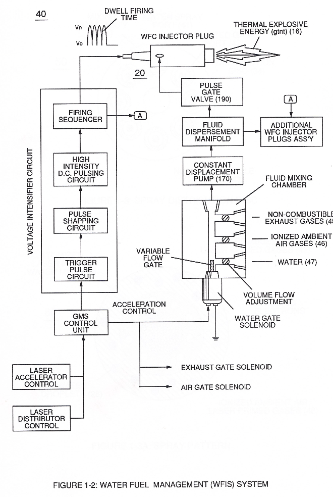
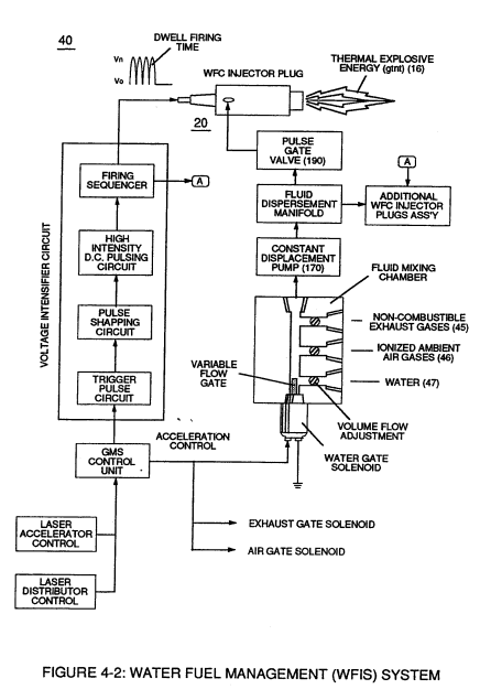
which simply uses Water Fuel Management (WFMS) System fluid-metering system (40) to control gas ignition (16), as illustrated in (40) of Figure (4-2). · Water Fuel Injection System - Page 4
-
(190) of Figure (3-23) · Tri - Coil Construction
-
Inductance Pulsing-Core (190) of Figure (3-23) · Inductance Reactance (Rs - Cd - FL)
-
Carries this number · Electron Bounce Phenomenon
-
(40) of Figure (4-2) · 8-5 - Energy Vectoring (Ev)
-
"FullSystem" development (10) of Figure (4-1) · WFC Development Objectives
-
Carries this number · Cover Page
-
Figure (3-5) · Acceleration Control Circuit (30)
-
Analog Voltage Circuit (40), as shown in Figure (3-5) · Acceleration Control Circuit (30)
-
Figure (3-5) · Acceleration Control Circuit (30)
-
Figure (3-5) · Analog Voltage generator (40)
-
Figure (3-27) · Voltage Intensifier Circuit (60)
-
The figure it sits on · Electrically Charged Water Molecule
-
Figure (3-5) · Laser Distributor
-
The figure it sits on · WFC 422DA - Illustrations
-
The figure it sits on · WFC 422DA - Illustrations
-
3-5 Outer Core Bobbin · Voltage Intensifier Coil Assembly
-
The figure it sits on · Electronic Circuit Design
-
Figure (29) · Water Fuel Injector (Taper Resonant Cavity Chamber)
-
(210) of Figure (3-27) (Memo WFC 422DA) · Covalent Switch-Off
-
(210) of Figure (3-27) · Inductance (FL)
-
(210) of Figure (3-27) · Electrovalent Bonding
Where it is named · 16
Voltage Intensifier Circuit (60) 2×
-
voltage intensifier circuit (190)
Inherently, then, pulsing core (53) of Figure (3-23) aids amp restriction while voltage intensifier circuit (190) is being "tuned" (adjusting pulse train 49a xxx 49n pulse-frequency 63 via pulse frequency generator 70 of figure 3-5) to match the resonant frequency properties of water bath (68) of Figure (3-22), as illustrated in Fuel Cell (120) of Figure (3-24).
-
interfacing voltage circuit (190)
The resultant interfacing voltage circuit (190), now, exposes water molecule (210) of Figure (3-27) to a pulsating high intensity voltage field (65a xxx 65n) of opposite polarity (66/67) while restricting amp flow within circuit (60) of Figure (3-22).
Voltage Dynamics 1×
-
electrical circuit (190)
Voltage potential (65) is an "unaltered" or "unchanged" energy-state when "electron movement" or "electron deflection" is prevented or restricted within electrical circuit (190) of Figure (3-23).
Electrically Charged Water Molecule 1×
-
voltage Intensifier circuit (190)
… cal force (66/67) can alter the electromagnetic properties of a atom since electromagnetic force is dependent on the movement of charged particles in a electrostatic field voltage Intensifier circuit (190) of figure (3-23), now, allows voltage to dissociates water molecule (85) by overcoming electrostatic bonding force (qq') between unlike atoms (76n7) while restricting amp flow, as illustrated in (160 …
Electrical Polarization process 1×
-
… pulse voltage potential (65) across Excitor plates (E1/E2) (voltage zones 66/67) of Figure (3-29) as to Figure (3-26) while inhibiting and preventing electron flow within voltage intensifier circuit (190) of Figure (3-23) causes water molecule (210) of Figure (3-27) to separate into its component parts (released hydrogen and oxygen gases) by pulling away (utilizing opposite attraction forces SS' and R …
Resonant Action 1×
-
voltage intensifier circuit (190)
By attenuating voltage amplitude (Vo xxx Yn) in conjunction with pulse-width (65a xxx 65n) allows voltage intensifier circuit (190) of Figure (3-23) to tune-in and match the resonant characteristics or resonant frequency of water bath (91) since water bath (91) always maintains its dielectric properties during pulsing operations.
Water Fuel Injection System 1×
-
Pulse Gate Valve (190)
Sequential pulsing of Water Fuel Injector (20/30) of Figure (1) as to (40) of Figure (2B) is system activated by Pulse Gate Valve (190) of Figure (1) to further control a predetermined energy-flame (16).
Water Fuel Injector (Taper Resonant Cavity Chamber) 2×
-
Quenching Disc Structure (190)
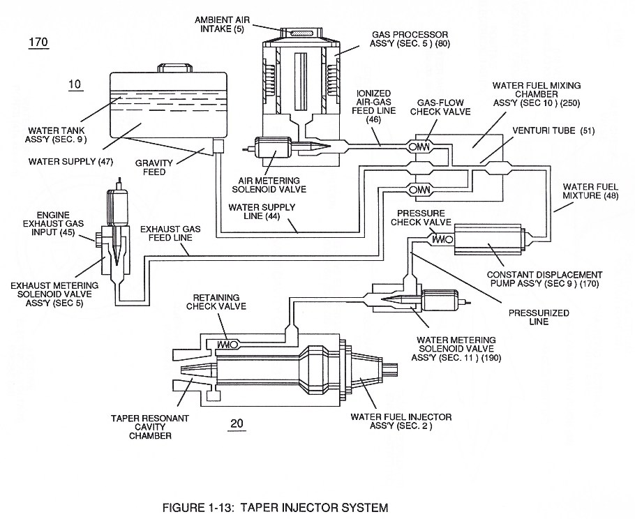
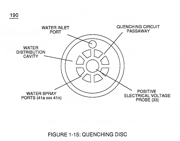
The resultant water fuel-mixture (48) is, now, pressurized up to and beyond 125 lbs of fluid-pressure by Fluid Displacement Pump (170) of Figure (13), as before, to cause and form water fuel-droplets (48a xxx 48n) when water fuel (48) enters into, passes through and beyond spray ports (41a xxx 41n) forming Quenching Disc Structure (190) of Figure (15).
Water Fuel Injection System - Page 4 1×
-
Pulse Gate Valve (190)
Sequential pulsing of Water Fuel Injector (20/30) of Figure (4-1) as to (40) of Figure (4-2) is system activated by Pulse Gate Valve (190) of Figure (4-1) to further control a predetermined energy-flame (16).
Water Fuel Injector 1×
-
… intensifier (VIC) circuit coil-assembly (580) of Figure (6-1) with 'Taper Resonant Cavity" (590) of Figure (6-2), as schematically illustrated in (60) of Figure (3-22) as to pulse core configuration (190) of Figure (3-23) (Memo WFC 422 DA) titled "WFC Hydrogen Gas Management System.
Tri - Coil Construction 2×
-
Resonant bobbin assembly (503), primary bobbin assembly (504), and secondary bobbin assembly (506), now, make up and structurally forms voltage intensifier (VIC) coil-assembly (530) of Figure (5-6) when electrical steel core material (53) forms a close-loop magnetic induction pathway centrally through and around (VIC) coil-assembly (530), as schematically illustrated in (190) of Figure (3-23) (Memo WFC 422 DA).
-
(190) of Figure (3-23)
Inductance Reactance (Rs - Cd - FL) 2×
-
Inductance Pulsing-Core (190)
At elevated or higher amplitude voltage levels (xxx Ve xxx Vf xxx Vn), primary electromagnetic coupling field (Rp) of Figure (7-8) transmitted by way of Inductance Pulsing-Core (190) of Figure (3-23) as to VIC Coil Assembly (580) of Figure (6-1) enters into and passes through both Inductors (L1/L2) simultaneously and offers not only further electron-flow restriction (Rp1/Rp2) to …
-
Inductance Pulsing-Core (190)
Inductance Pulsing-Core (190) of Figure (3-23)
Electron Bounce Phenomenon 1×
-
… igh Voltage Potential of Difference (Vo - Vn) (SS' - 617 -RR') is accomplished when magnetic flux lines of force (71a xx 71n) (Rp) emanating away from closed-loop magnetic pulsing core (53) of Figure (190) penetrates Inductance coil-windings (52 - 56 - 62) simultaneously during each and every pulse on-time (T1a xxx T1n) as programmable pulse-train (49a xxx 49n T3 - 49a xxx 49n) is adjusted to "Tune - i …