(E9) · also written as a run, E9a xxx E9n
Capacitor
Also written Voltage Zones · positive electrical voltage surface · electrical conducting plates · Electrical Voltage-Plates · surfaces
Where it is first named
… gure (3-30) as to (270) of (3-34) ionizes the highly energized combustible gases to decrease atomic mass while applied traveling voltage wave-form (57) of Figure (6-2) of opposite electrical polarity (E9-66/ ElO-67) initiates the voltage-triggering process (600) of Figure (6-3) once maximum voltage deflection (VO - Va - Vb - Vc - Vn) of Figure (6-4) is achieved at Activation-Point (E9d) of Figure (6-2) ... …
How it is written
- (E9/E10) 11× with (E10) Capacitor
- (E9/EI0) 2× with (EI0) Voltage Zones
- (E9/10) 2× with (10) Led Pickup Circuit
- (E9a xxx E9n) 2×
- (E9-66/ ElO-67) 1× with (66) Positive Voltage Potential, (ElO), (67) Opposite Polarity
- (E9a - b - c - d) 1×
- (E9a - b - c - d - E9n) 1×
- (E9 / EI0) 1× with (EI0) Voltage Zones
E9a xxx E9n is Meyer's shorthand for a run of the same thing: E9a is the first, E9n the last, and the x's stand for however many lie between. Every stage of the run is this one numeral.
Drawings 95
-
(650) of Figure (7-4) · Amp Inhibiting Circuit Vs Voltage Enhancement
-
(616) of Figure (7-11) · Instant Explosion of Water
-
(650) of Figure (7-4) · Resistance (Rs)
-
(720) of Figure (7-11) · Inductance (FL)
-
(720, 616) of Figure (7-11) · Inductance (FL)
-
Carries this number · Inductance (FL)
-
Capacitor (E9/E10) of Figure (7-11) · Inductance (FL)
-
(650) of Figure (7-4) · Inductance (FL)
-
(720) of Figure (7-11) · Capacitance (Cd)
-
(650) of Figure (7-4) · Capacitance (Cd)
-
(730) of Figure (7-12) · Taper Resonant Capacitor (ERt)
-
(see diagram 720 of Figure 7-11) · Taper Resonant Capacitor (ERt)
-
diagram 720 of Figure 7-11 · Taper Resonant Capacitor (ERt)
-
"Voltage Deflection" of Figure (7-4) · Capacitance Reactance
-
Opposite Electrical Attraction Force (SS' ~ 617 ~ RR' - T3 - SS' ~ 617 - RR') of Figure (7-4) · Electron Bounce Phenomenon
-
Traveling Electrical Voltage Wave-forms (730a - b - c) of Figure (7-12) · Electron Bounce Phenomenon
-
(E9/10) of Figure (6-2) · Voltage Amplitude Switch-Off
-
Compressional Wave-form (B) of Figure (7-12) · Voltage Amplitude Switch-Off
-
Carries this number · Mode of Operability
-
Carries this number · WFC 426 - Illustrations
-
Carries this number · WFC 426 - Illustrations
-
Carries this number · WFC 426 - Illustrations
-
(730A) of Figure (7-12) · 8-2 - Traveling Voltage Wave-Guides
-
(570) of Figure (7-12) · 8-2 - Traveling Voltage Wave-Guides
-
(720) of Figure (7-11) · 8-2 - Traveling Voltage Wave-Guides
-
Carries this number · 8-2 - Traveling Voltage Wave-Guides
-
(770) of Figure(8-1) · 8-2 - Traveling Voltage Wave-Guides
-
(770) of Figure (8-1) · 8-3 - Electrical Voltage-Pulse Wave-Transmission
-
(770 A) of Figure (8-1) · 8-4 - State Space (Sp)
-
(650) of Figure (7-4) · 8-4 - State Space (Sp)
-
(730) of Figure (7-12) · 8-5 - Energy Vectoring (Ev)
-
(770A) of Figure (8-1) · 8-5 - Energy Vectoring (Ev)
-
(612) of Figure (8-1) · 8-5 - Energy Vectoring (Ev)
-
Carries this number · 8-6 - VIC Voltage Sync-Pulse Circuit
-
(650) of Figure (7-4) · 8-6 - VIC Voltage Sync-Pulse Circuit
-
(730A) of Figure (7-12) · 8-7 - Application of Usage
-
Carries this number · WFC 427 Illustrations
-
"Voltage Tickling of State Space" (770A) of Figure (8-1) · WFC Exhaust Air Reclaimer
-
"Voltage Tickling of State Space" (770B) of Figure (8-1) · WFC Exhaust Air Reclaimer
-
Carries this number · Propagating Electrical Stress
-
The programmable pulse-frequency (49a xxx 49n) of Figure (10-1) input is simply adjusted to tune-in to the dielectric property of the Water Molecule. · Propagating Electrical Stress
-
Dynamic Electrical Charging Effect (612) of Figure (8-1) · Propagating Electrical Stress
-
Carries this number · Quartz Tube Configuration & Operational Parameters
-
Carries this number · Quartz Tube Configuration & Operational Parameters
-
... establishing variable Dynamic Electrical Charging Effect (612). · Quartz Tube Configuration & Operational Parameters
-
Carries this number · WFC 429 - Illustrations
-
Carries this number · Wobbling Effect
-
(970) of Figure (10-1) · VIC Switchover Circuit
-
Figure (3-20) · Voltage Intensifier Circuit (60)
-
The figure it sits on · WFC 422DA - Illustrations
-
The figure it sits on · WFC 422DA - Illustrations
-
(57) of Figure (6-2) · In Application of Usage
-
Activation Process (590) of Figure (6-2) · Voltage Intensifier Coil-Assembly
-
"Voltage Intensity of Opposite Potential" (600) of Figure (6-3) · Voltage Intensifier Coil-Assembly
-
The figure it sits on · WFC 425 - Illustrations
-
The figure it sits on · VIC Matrix Circuit
-
Voltage Intensifier Circuit (620) of Figure (7-1) · Instant Explosion of Water
-
(T2) of Figure (7-8) · Instant Explosion of Water
-
(620) of Figure (7-1) · Instant Explosion of Water
-
Figure (7-8) · Resistance (Rs)
-
(620) of Figure (7-1) · Resistance (Rs)
-
(690) of Figure (7-8) · Resistance (Rs)
-
(600) of Figure (6-3) · Inductance (FL)
-
(614) of Figure (7-1) · Inductance (FL)
-
(690) of Figure (7-8) · Inductance (FL)
-
Inductor (614) of Figure (7-1) · Inductance (FL)
-
(600) of Figure (6-3) · Inductance (FL)
-
(614) of (7-1) · Inductance (FL)
-
Figure (7-1) · Capacitance (Cd)
-
(590) of Figure (6-2) · Capacitance (Cd)
-
(690) of Figure (7-8) · Capacitance (Cd)
-
(690) of Figure (7-8) · Inductance Reactance (Rs - Cd - FL)
-
Figure (7-8) · Inductance Reactance (Rs - Cd - FL)
-
(620) of Figure (7-1) · Inductance Reactance (Rs - Cd - FL)
-
(370) of Figure (3-40) · Taper Resonant Capacitor (ERt)
-
(690) of Figure (7-8) · Taper Resonant Capacitor (ERt)
-
Quenching Circuit (370) of Figure (3-40) · Capacitance Reactance
-
690 of Figure 7-8 · Circuit Resistance
-
Choke-Coil (62) of Figure (7-1) · Transformer Action
-
(52) of Figure (7-8) · Electron Bounce Phenomenon
-
The figure it sits on · WFC 426 - Illustrations
-
The figure it sits on · 8-1 - Propagating "Resonant Action" By Voltage Tickling of State Space
-
(690) of Figure (7-8) · 8-2 - Traveling Voltage Wave-Guides
-
(52) of Figure (7-8) · 8-3 - Electrical Voltage-Pulse Wave-Transmission
-
(Cp) of Figure (7-8) · 8-4 - State Space (Sp)
-
(770 B) of Figure (8-1) · 8-4 - State Space (Sp)
-
(585) of Figure (8-1) · 8-4 - State Space (Sp)
-
(620) of Figure (7-1) · 8-6 - VIC Voltage Sync-Pulse Circuit
-
(690) of Figure (7-8) · 8-6 - VIC Voltage Sync-Pulse Circuit
-
(Cp) of (7-8) · 8-6 - VIC Voltage Sync-Pulse Circuit
-
(730C) of Figure (7-12) · 8-7 - Application of Usage
-
(690) of Figure (7-8) · Propagating Electrical Stress
-
"Resonant Charging Choke" (56) of Figure (7-1) · Propagating Electrical Stress
-
(620) of figure (7-1) · Voltage to Amp Differential Ratio
-
The figure it sits on · WFC 429 - Illustrations
Where it is named · 26
In Application of Usage 1×
-
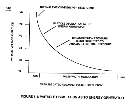
… gure (3-30) as to (270) of (3-34) ionizes the highly energized combustible gases to decrease atomic mass while applied traveling voltage wave-form (57) of Figure (6-2) of opposite electrical polarity (E9-66/ ElO-67) initiates the voltage-triggering process (600) of Figure (6-3) once maximum voltage deflection (VO - Va - Vb - Vc - Vn) of Figure (6-4) is achieved at Activation-Point (E9d) of Figure (6-2) ... …
Water Fuel Injector 5×
-
... dielectric value of water being 78.54 since water molecule (85) oxygen atom "L" orbit (76) occupies the maximum allowance eight electrons (79a xxx 79n), calibrated gated unipolar pulse train (64a xxx 64n) of Figure (3-20) is outputted from resonant choke (56) and electrically transmitted to positive outer conical surface (E9);
-
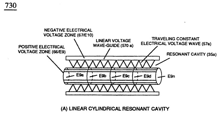
while, at the same time, negative potential of electrical intensity of force (67) (negative voltage potential) is electrically directed to inner conical surface (E1O), forming an "open-air" conical cavity (570) having parallel sides (in other cases non-linear voltage-surfaces) in space relationship (typically .010 gap) with diminishing circumference-area (E9a xxx E9n) / E10a xxx E10n) in linear progression.
-
Together, parallel sides (E9 / El0) not only functions as a "voltage wave-guide" (570) but, also, acts and performs as a "voltage intensifier circuit" when applied gated pulse-frequency (64a xxx 64n) travels the length of conical cavity (570) toward exit port (32).
-
At each progressive point of diminishing circumference surface-area (E9a - b - c - d - E9n) voltage amplitude intensity increases (Vna - b - c - d - Vnn) uniformly, as illustrated in (600) of Figure (6-3) as to Travelling Voltage Wave-forms (730a - b - c) of Figure (7-12), see WFC Memo (426).
-
All activation points (E9a - b - c - d) performing their respective functions in sequential order in an instant of time since applied voltage level of intensity (typically 20,000 input volts or so) can be extended or increased up to and beyond 90,000 volts range within a millisecond or less.
Taper Water Fuel Injectors 1×
-
Voltage wave-guide (570) allows the activation points (E9a xxx E9n) to transpire since wave-guide (570), now, functions as a Quenching Circuit (370) of Figure (3-40) to prevent gas ignition until the traveling gases (under static pressure) are exited out of and away from exit port (32) of Figure (6- 2)
Inductance (FL) 4×
-
Capacitor (E9/E10)
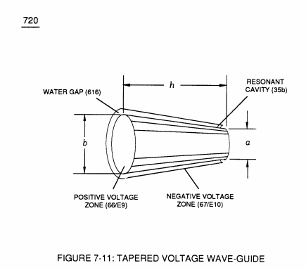
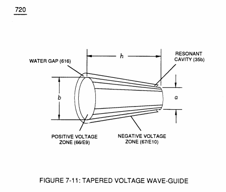
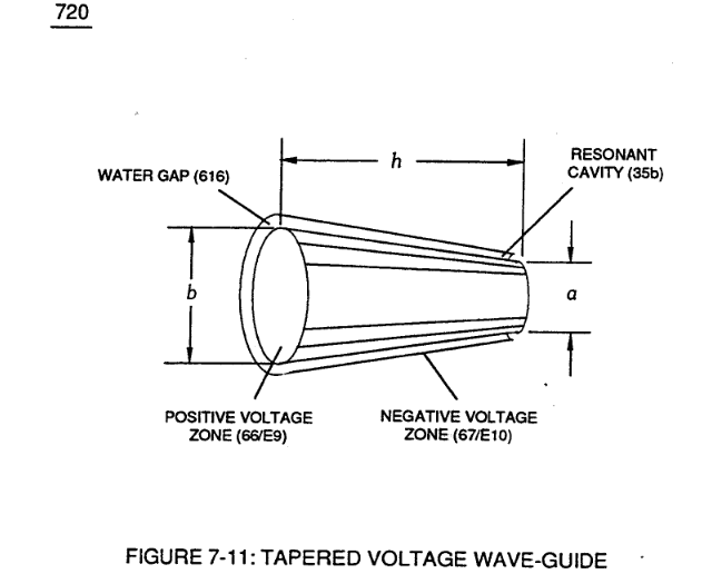
Capacitor (E9/E10) of figure (6-2) as to (720) of Figure (7-11) is formed when outer tapered surface (66) and inner tapered surface (67) forms Water-Gap (616) of Figure (7-11) as to Figure (590) of Figure (6-2) having …
-
Capacitor (E9/E10)
Component Reactance to D.C. pulsing transforms Inductor (614) of Figure (7-1) / Capacitor (E9/E10) of Figure (7-11) LC circuit of Figure (7-2) into an Resonant Charging Choke (614) which steps up an unipolar oscillation of an given charging frequency with the effective capacitance of a pulse-formi …
-
Voltage Zones (E9/E10)
… nipolar oscillation of an given charging frequency with the effective capacitance of a pulse-forming network (64a xxx 64n) of Figure (7-1) as to (600) of Figure (6-3) in order to charge Voltage Zones (E9/E10) to a higher potential beyond applied voltage input
Capacitance (Cd) 5×
-
Capacitor (E9/E10)
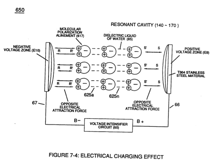
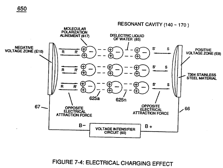
Capacitor (E9/E10) of Figure (7-1) as to Figure (650) of Figure (7-4) in direct relationship to Water Gap (616) becomes Taper Resonant Cavity (720) of Figure (7-11) as shown in (590) of Figure (6-2) since Water Gap (616) is occupied by a dielectric liquid (Re) as herein before identified as natural water (85) having no electrolyte added thereto
-
Voltage Zones (E9/EI0)
In like manner, the stainless steel (s/s) T304 material that forms Voltage Zones (E9/EI0) undergo particle alignment of its atomic structure within the atomic infrastructure of plate-material (E9/E10) when exposed to the same applied electrical voltage fields (66/67) after a pre-set time
-
In like manner, the stainless steel (s/s) T304 material that forms Voltage Zones (E9/EI0) undergo particle alignment of its atomic structure within the atomic infrastructure of plate-material (E9/E10) when exposed to the same applied electrical voltage fields (66/67) after a pre-set time
-
... causing molecular electrical movement to occur within the surface-material (E9/EI0)
-
electrical conducting plates (E9/E10)
… nant Cavity (720) of Figure (7-11) as to (650) of Figure (7-4) forms capacitor (ER) of Figure (7-1) when the dielectric liquid of water (85) is placed or injected between electrical conducting plates (E9/E10) while applied voltage Potential of opposite polarity (66/67) is directly exposed to Water Molecules (85a xxx 85n), as depicted in Taper Resonant Cavity (590) of Figure (6-2) as to (650) of Figure (7- …
Taper Resonant Capacitor (ERt) 2×
-
The dielectric property of water (being 78.54 ohms @ 25° C) permits the storage of '"Electrical Charge" when a potential voltage difference exists between Electrical Voltage-Plates (E1/E2) as to (E9/E10).
-
Electrical Voltage-Plates (E1/E2 - E9/E10)
Capacitance (Cp) of Figure (7-6) as to (690) of Figure (7-8) is determined by the surface area (A) of Electrical Voltage-Plates (E1/E2 - E9/E10), the distance (d) between the Electrical Plates (in inches), and the permittivity (Eo) of the dielectric property of water (85) and, is expressed in the following equation:
Voltage Amplitude Switch-Off 2×
-
surfaces (E9/10)
Voltage levels of variance (Va xxx Vn) is achieved by simply switching-in or switching-out the member of Secondary Coil-cavities (505a xx 505n) (see 740 of Figure 7-13) in direct relationship to Taper Resonant Voltage surfaces (E9/10) of Figure (6-2) which acts and performs as a "Voltage Amplifier" when Compressional Wave-form (B) of Figure (7-12) is intensified at Exit Port (32) of Figure (6-2).
-
(E9/10) of Figure (6-2)
8-2 - Traveling Voltage Wave-Guides 5×
-
positive electrical voltage surface (66/E9)
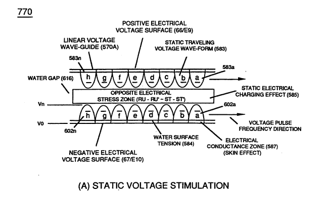
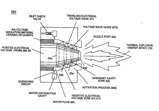
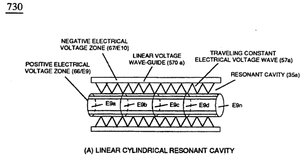
The formation of tubular Traveling Voltage Wave-guide (570a) of Figure (7-12) (WFC Memo 426) as to (770) of Figure (8-1) is physically formed when positive electrical voltage surface (66/E9) and negative electrical voltage surface (67/E10) are placed in parallel space relationship to form voltage surfaces (E9/E10) about an cylindrical axis of rotation having space-gap (35) there between …
-
… Figure (8-1) is physically formed when positive electrical voltage surface (66/E9) and negative electrical voltage surface (67/E10) are placed in parallel space relationship to form voltage surfaces (E9/E10) about an cylindrical axis of rotation having space-gap (35) there between and thus, fanning Cylindrical Resonant Cavity (730A) of Figure (7-12) as to (770A) of Figure (8-1) when space-gap (616) of Fi …
-
The surface tension of water (584) adjacent to both voltage surfaces (E9 / EI0) further aids the transmission of voltage potential (66/67) since Electrical Charging Effect (585) of Figure (7-4) does not change or alter the dielectric value of water (Re).
-
Together, the Voltage Coefficient of Water (e/Eo) of Equation (Eq 21) and the Voltage Coefficient of the stainless steel (s/s) material fanning voltage surfaces (E9/E10), now, allows the establishment and performance of Traveling Electrical Voltage Wave-Guide (583/602) since electrical conductance zone (587) between electrical surface (S) (E9/E10) and the dielectric …
-
… ng voltage surfaces (E9/E10), now, allows the establishment and performance of Traveling Electrical Voltage Wave-Guide (583/602) since electrical conductance zone (587) between electrical surface (S) (E9/E10) and the dielectric surface tension of water (584) acts and performs as a electrical conductor (Skin Effect)
Quartz Tube Configuration & Operational Parameters 1×
-
Voltage Zones (66/E9 – 67/E10)
The Electrical Conduction Zone (587) (Skin Effect) between the dielectric gas medium (919) and the Electrical Contact Surface of the inside surface area of the Voltage Wave-Guides (66/67) allows Unipolar Pulse Train (583a/602a-583b/602b - 583n/602n) to travel the entire length of the Voltage Wave Guides that make up Voltage Zones (66/E9 – 67/E10).