(100) · also written as a run, 100a xxx 100n
Hydrogen Fracturing Process
Also written Hydrogen Gas Control Circuit · electromagnetically primed destabilized gas atoms · gas ignition stage · Fuel Cell System
Where it is first named
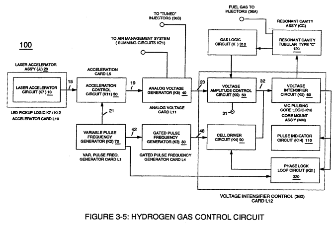
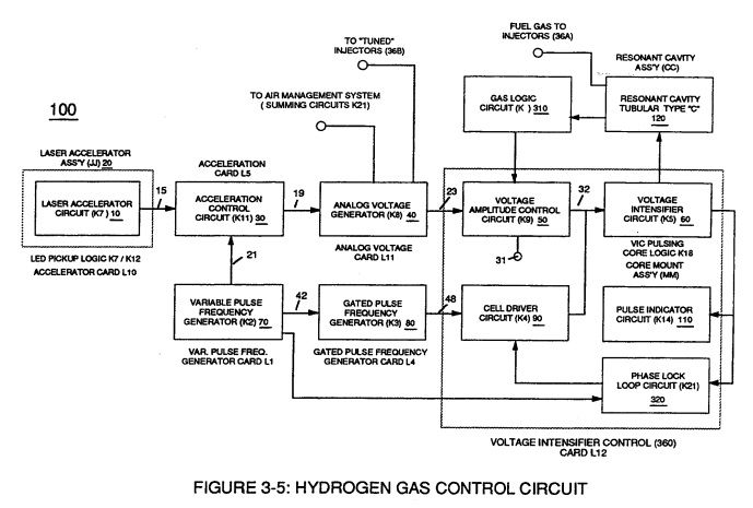
In both cases, pulse frequency range of each clock signal (21) and (42) can be altered or change (controlled independent of each other) to obtain peak performance of Fuel Cell System (100) of Figure (3-5).
How it is written
- (100) 29×
- (100 / 390) 1× with (390) Hydrogen Fracturing Process
- (l04a xxx 100n) 1×
100a xxx 100n is Meyer's shorthand for a run of the same thing: 100a is the first, 100n the last, and the x's stand for however many lie between. Every stage of the run is this one numeral.
Drawings 76
-
Figure (3-5) · Acceleration Control Circuit (30)
-
Analog Voltage Circuit (40), as shown in Figure (3-5) · Acceleration Control Circuit (30)
-
Figure (3-5) · Acceleration Control Circuit (30)
-
Figure (3-5) · Analog Voltage generator (40)
-
Figure (3-6) · Voltage Amplitude Control Circuit (50)
-
Figure (3-6) · Cell Driver Circuit (90)
-
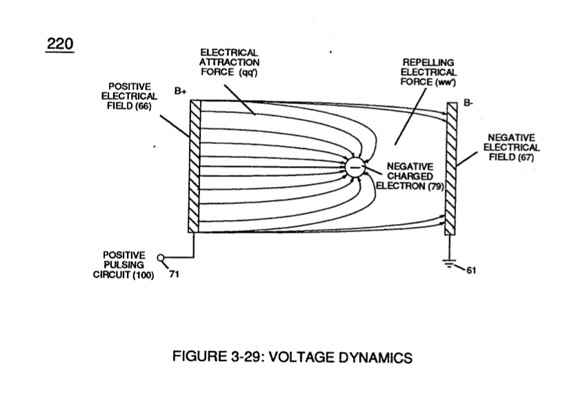
In both cases, electrical charge deflection or movement is directly related to applied voltage (65). · Voltage Dynamics
-
Figure (3-29) · Electrically Charged Water Molecule
-
(340) of Figure (3-38) · Gas Modulator Process
-
engine cylinder (102) of Figure (3-38) · Gas Processor
-
Figure (3-5) · Laser Distributor
-
Carries this number · WFC 422DA - Illustrations
-
Carries this number · WFC 422DA - Illustrations
-
Carries this number · WFC 422DA - Illustrations
-
Carries this number · WFC 422DA - Illustrations
-
Carries this number · Water Fuel Injection System
-
Carries this number · Water Fuel Injection System
-
Carries this number · Voltage Intensifier Coil Assembly
-
Carries this number · Electronic Circuit Design
-
Carries this number · Electronic Circuit Design
-
Carries this number · Electronic Circuit Design
-
Carries this number · Electronic Circuit Design
-
Carries this number · Electronic Circuit Design
-
Carries this number · Electronic Circuit Design
-
Carries this number · Electronic Circuit Design
-
Carries this number · Electronic Circuit Design
-
Carries this number · Electronic Circuit Design
-
Carries this number · Electronic Circuit Design
-
Carries this number · Electronic Circuit Design
-
Carries this number · Electronic Circuit Design
-
Carries this number · Electronic Circuit Design
-
Carries this number · Electronic Circuit Design
-
Carries this number · Electronic Circuit Design
-
Carries this number · Electronic Circuit Design
-
Carries this number · Electronic Circuit Design
-
Carries this number · Electronic Circuit Design
-
Carries this number · Electronic Circuit Design
-
Carries this number · Differential Air-Gas Inlet Control
-
Carries this number · Differential Air-Gas Inlet Control
-
Carries this number · Differential Air-Gas Inlet Control
-
Carries this number · Differential Air-Gas Inlet Control
-
Figure (17) · Water Fuel Injector (Taper Resonant Cavity Chamber)
-
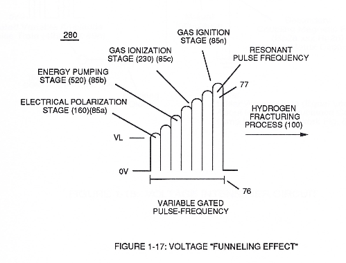
Carries this number · Funneling Effect
-
thereby, attenuating voltage amplitude (voltage intensity) beyond Secondary Coil (53) voltage levels (71), as illustrated in (220) of Figure (18). · Funneling Effect
-
Carries this number · Funneling Effect
-
2-2 Plug Housing · Water Fuel Injector Illustrations
-
2-3 Water Inlet Housing · Water Fuel Injector Illustrations
-
2-6 Ceramic Insert · Water Fuel Injector Illustrations
-
Carries this number · Steam Resonator Assembly
-
Carries this number · Steam Resonator Assembly
-
Figure (3-6) · Water Fuel Injection System - Page 1
-
Figure (4-8) · Water Fuel Injection System - Page 2
-
(100) of Figure (4-8) · In Application of Usage
-
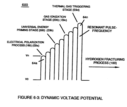
"Voltage Intensity of Opposite Potential" (600) of Figure (6-3) · Voltage Intensifier Coil-Assembly
-
(100) of Figure (4-8) · Voltage Intensifier Coil-Assembly
-
Carries this number · WFC 425 - Illustrations
-
(600) of Figure (6-3) · Inductance (FL)
-
(600) of Figure (6-3) · Inductance (FL)
-
(100) of Figure (4-8) · Capacitance Reactance
-
Voltage Dynamics (220) of Figure (3-29) · Electron Bounce Phenomenon
-
Carries this number · 8-1 - Propagating "Resonant Action" By Voltage Tickling of State Space
-
Voltage Dynamics (220) of Figure (3-29) · WFC Exhaust Air Reclaimer
-
This atomic thermal-interaction between sub-critical combustible gas atoms (127 and 128a/b) is, now, herein after called "The Hydrogen fracturing Process. " · Hydrogen Fracturing Process
-
The figure it sits on · WFC 422DA - Illustrations
-
3-5 Outer Core Bobbin · Voltage Intensifier Coil Assembly
-
(390) of Figure (41) · Water Fuel Injector (Taper Resonant Cavity Chamber)
-
The figure it sits on · Funneling Effect
-
Hydrogen Fracturing Process (390) of Figure (3-42) · Water Fuel Injection System - Page 1
-
(390) of Figure (3-42) · In Application of Usage
-
coil-structures (580) of Figure (6-1) · Voltage Intensifier Coil-Assembly
-
(390) of Figure (3-42) · Resistance (Rs)
-
(580) of Figure (6-1) · Inductance (FL)
-
(580) of Figure (6-1) · Multi-layer Coil
-
(390) of Figure (3-42) · Capacitance Reactance
-
(580) of Figure (6-1) (WFC memo 425) · 8-2 - Traveling Voltage Wave-Guides
-
(580) of Figure (6-1) · Voltage to Amp Differential Ratio
Where it is named · 31
Variable Pulse Frequency Generator (70) 1×
-
Fuel Cell System (100)
In both cases, pulse frequency range of each clock signal (21) and (42) can be altered or change (controlled independent of each other) to obtain peak performance of Fuel Cell System (100) of Figure (3-5).
Voltage Intensifier Circuit (60) 1×
-
Hydrogen Gas Control Circuit (100)
Analog voltage signal (32a xxx 32n) of Figure (3-15) allows pulse train (51a xxx 51n) voltage amplitude (V0 xxx Vn) of Figure (3-19) to vary from one up to twelve volts (battery supply 28 of Figure 3-6 by attenuating Laser Accelerator circuit (10) of Figure (3-5) via Hydrogen Gas Control Circuit (100).
Gas Processor 1×
-
electromagnetically primed destabilized gas atoms (l04a xxx 100n)
… ing circuit (270) dislodges, captures, and immediately consumes ejected electrons (117a xxx) In other words, ambient air gases (101) has, now, become electromagnetically primed destabilized gas atoms (l04a xxx 100n) having missing electrons.
Laser Distributor 1×
-
Hydrogen Gas Control Circuit (100)
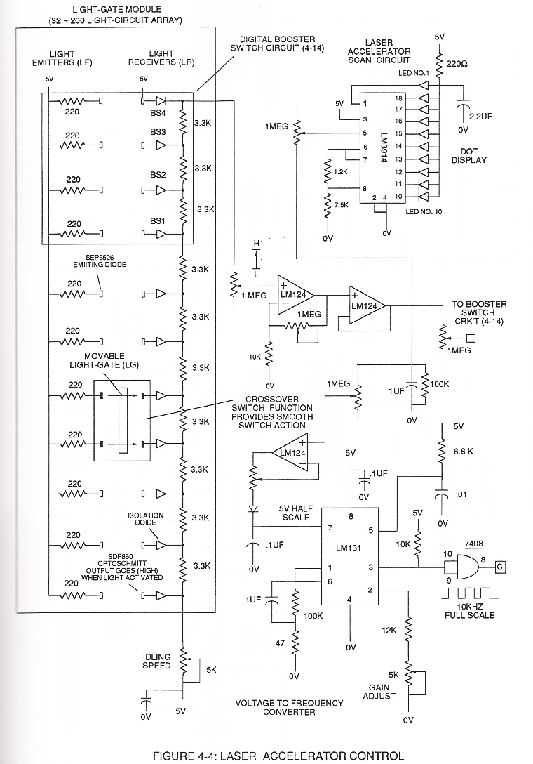
Interlocking Laser Accelerator output {JJ) with Laser Distributor output (HH) of Figure (3-1) causes Fuel-Injectors (36) to be "Tuned" with both Air Management System (350) of Figure (3-2) and Hydrogen Gas Control Circuit (100) of Figure (3-5) to maintain constant Fuel-mixing Ratio (290) of Figure (3-3) during engine performance.
Water Fuel Injection System 2×
-
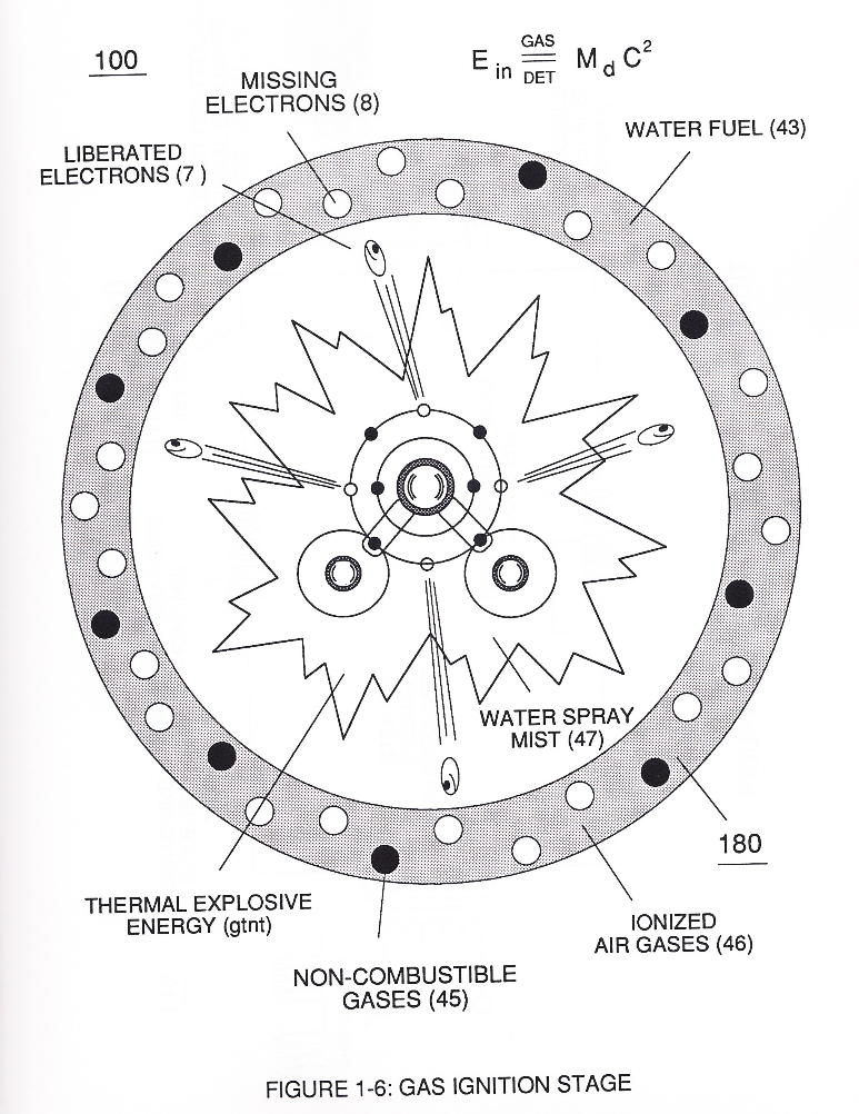
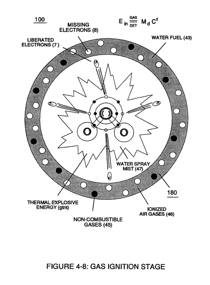
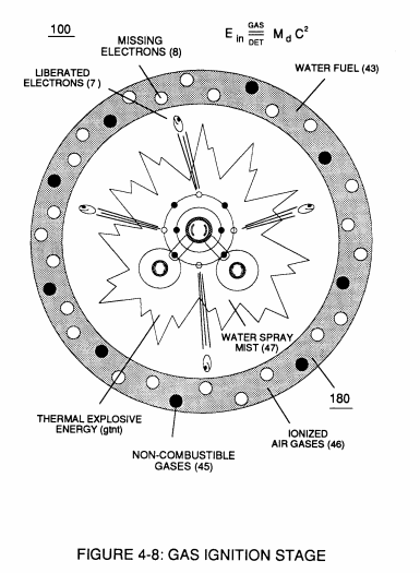
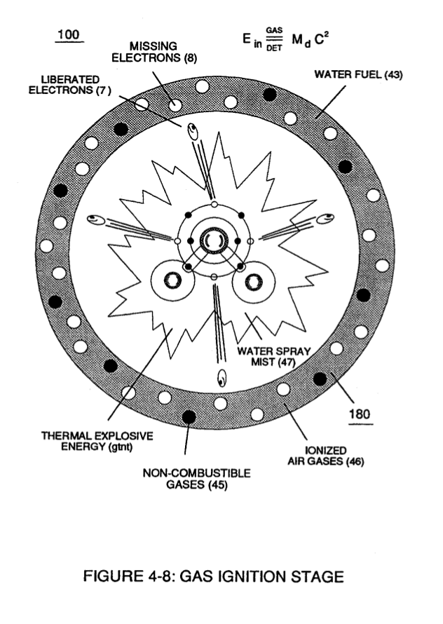
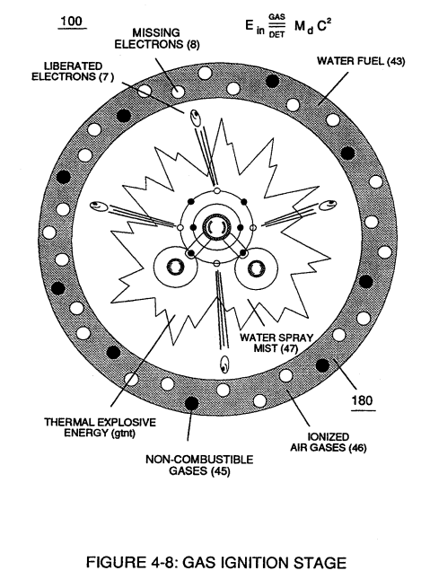
That, whenever the mass-size of a combustible gas atom is decreased (Md), thermal explosive energy-yield (gtnt) is increased (Ein) during thermal gas combustion (Gas // Detonation.), as so illustrated in (100) Figure (6) as to (90) of Figure (5).
-
Hydrogen Fracturing Process (100)
Injected non-combustible gases (45a xxx 45) retards and controls the combustion rate of the Hydrogen Fracturing Process (100) of Figure (6) during gas-ignition.
Water Fuel Injector (Taper Resonant Cavity Chamber) 7×
-
gas ignition stage (100)
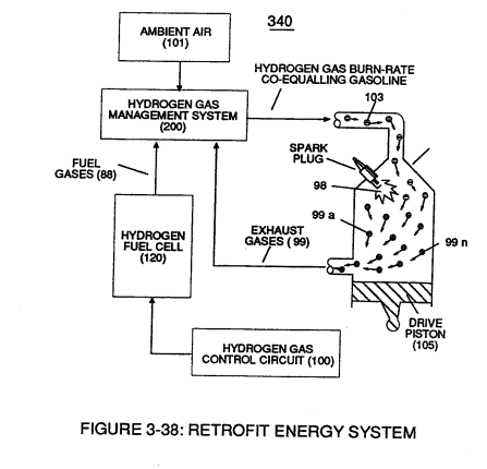
To set up, trigger, and perform Hydrogen Fracturing Process (390) of Figure (3-42) (see WFC Memo 422 DA) gas ignition stage (100) of Figure (6) ...
-
(100) of Figure (6)
-
Hydrogen Fracturing Process (100)
… njection System (10) of Figure (1) as to (170) of Figure (13) incorporates and uses Taper Resonant Cavity Chamber (180) of Figure (14) to enhance operational parameters of Hydrogen Fracturing Process (100) of Figure (6) being stimulated to activation by opposite electrical voltage fields (49/51) of Figure (3B) as to (180) of Figure (14).
-
Hydrogen Fracturing Process (100)
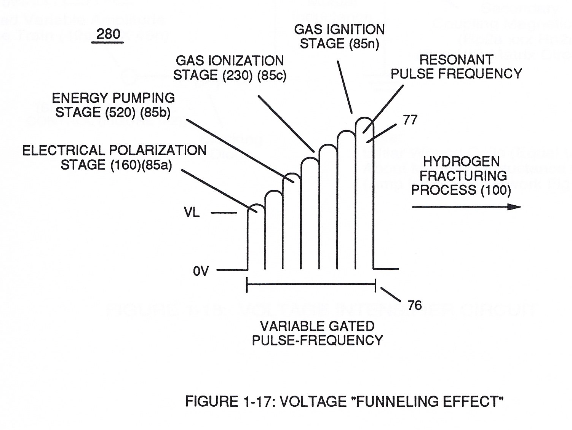
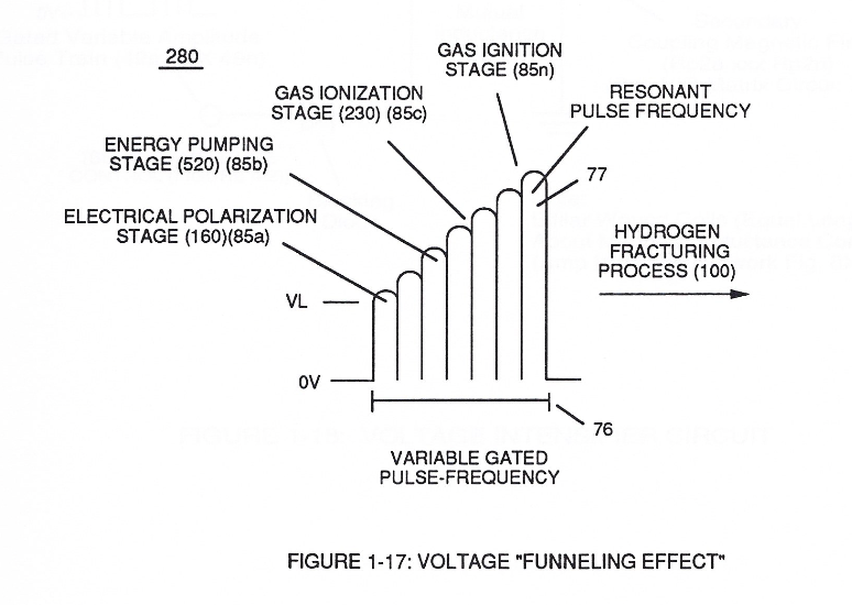
… on of applied gated electrical voltage pulse-train (210a xxx 210n) of Figure (17) to continued in-flow of water fuel droplets (48a xxx 48n) not only sustains and maintains Hydrogen Fracturing Process (100) of Figure (6) but, also, regulates Thermal Explosive Energy release (16a x 16n) of Figure (14) by attenuating applied voltage amplitude (xxx VL xxx), as graphically shown in Figure (20F) (WFC Memo 42 …
-
Voltage Intensifier Circuit (220) of Figure (18) allows Electrical-Stress variation (SS' = RR' / TT' = UU') since voltage Intensifier Circuit (220) inhibits electron-flow (amp restriction) into voltage triggering process (210) of Figure (17) as to (100) of Figure (6).
-
(100) of Figure (6)
Funneling Effect 4×
-
Hydrogen Fracturing Process (100)
Enhancement of the operational parameters of Hydrogen Fracturing Process (100) of Figure (6) is further exemplified when incoming Resonant voltage-wave (58) of Figure (18) electrically transmitted across Resonant Cavity Zone (35) during water injection cycle...
-
Hydrogen Fracturing Process (100)
To increase energy levels (16a xxx 16L = 16n) of Hydrogen Fracturing Process (100) as to (390), even further, simply switch-on additional Booster Coils (61a x 61L - 61n) in sequential order to increase voltage intensity (VL ~ Vn ~ Vm) to higher magnitude of "Electrical Force" (Vma …
-
Hydrogen Fracturing Process (100)
This resultant "Shunting Effect", now, allows voltage intensity (Vma = Vmn) to be placed across Resonant Cavity Zone (35) to not only compensate for water impurity that might alter the operational parameters of Hydrogen Fracturing Process (100) as to (390) but, also, provide "Instant" "Power-Boost" when needed.
-
Hydrogen Fracturing Process (100 / 390)
This newly formed synchronized and repetitive dual expanding voltage wave form (77a xxx 77n) is further enhanced by "Funneling Effect" (260)... maximizing voltage dynamic across Resonant Cavity (35) always subjecting and exerting increase "Electrical-Stress" (SS'-RR' / TT'-UU') of opposite polarity across Hydrogen Fracturing Process (100 / 390) to the point of gas ignition.
Water Fuel Injection System - Page 3 2×
-
That, whenever the mass-size of a combustible gas atom is decreased (Md), thermal explosive energy-yield (gtnt) is increased (Ein) during thermal gas combustion (Gas // Detonation), as so illustrated in (100) Figure (4-8) as to (90) of Figure (4-7).
-
Hydrogen Fracturing Process (100)
In other or alternate applications, laser primed ionized liquid oxygen (68) of Figure (1-21) (see WFC memo 420) and laser primed liquid hydrogen (69) of Figure (1-21) stored in separate fuel-tanks can be used in place of fuel-mixture (48); or, liquefied ambient air gases (6) alone with water-source (8) can, also, be substituted as a fuel-source (48) to trigger Hydrogen Fracturing Process (100).
In Application of Usage 2×
-
The Hydrogen Fracturing Process (390) of Figure (3-42) simply triggers and releases atomic energy (gtnt) from natural water (85) of Figure (3-26) by retarding and preventing the reformation of the water molecule being subjected to sub-critical state (520) of Figure (5-3) during thermal gas ignition (100) of Figure (4-8) as to (70) of Figure (4-5).
-
(100) of Figure (4-8)
Water Fuel Injector 2×
-
Activation point (E9a) exposes water flow (85) to voltage wave-form (64) of Figure (6-1) to begin water-to-energy conversion process (100);
-
and finally, activation point (E9d) thermally ignites (atomic agitation) the "Energy-Primed" combustible gas-mixture (520) of Figure (5-3) as to (100) of Figure (4-8) by "electrostatic discharge" while being subjected to ever increasing "electrostatic pressure".
Voltage Intensifier Coil-Assembly 4×
-
Activation Process (590) of Figure (6-2) as to (100) of Figure (4-8) is achieved since amp flow is restricted to enter into Voltage Triggering Process (70) of Figure (4-5) by way of voltage intensifier coil-assembly (580) of Figure (6-1).
-
(100) of Figure (4-8)
-
… (minimizing amp leakage) by which "Voltage Intensity of Opposite Potential" (600) of Figure (6-3) can perform work to trigger Hydrogen Fracturing Process (520) of Figure (5-3) (Memo WFC 424 DA) as to (100) of Figure (4-8) (Memo WFC 423DA), as graphically denoted in (750) of Figure (7-14) of WFC memo (426) titled VIC Matrix Circuit - Instant Explosion of Water.
-
(100) of Figure (4-8)
Capacitance Reactance 2×
-
... to bring-on and trigger Hydrogen Fracturing Process (390) of Figure (3-42) once liberated and expanding water gases (100) of Figure (4-8) passes beyond exit port (E9d)
-
(100) of Figure (4-8)
Electron Bounce Phenomenon 2×
-
... triggering Hydrogen Fracturing Process (90) of Figure (5-5) as to (100) of Figure (4-8) ... instantly releasing thermal explosive energy (gtnt) (16) from Water (85) on demand, as illustrated in Taper Resonant Cavity (590) of Figure (6-2) as to (70) of Figure (4-5).
-
(100) of Figure (4-8)