(85) · also written as a run, 85a xxx 85n
Water Molecule
Also written water · Dielectric Value of Water · natural water · rain water · water bath · Dielectric Water Bath · injected water bath · water molecules and 5 more
Where it is first named
Voltage potential (65) within electrical circuit (60) can cause one or more electrons (79) to be dislodged from the water molecule atom (85) of Figure (3-26) due to opposite electrical polarity attraction (qq') of Figure (3-29) between unlike charged entities, as shown in (160) of Figure (326) as to Newton's and Coulomb's laws of electrical-force.
How it is written
- (85) 37×
- (85/Re) 3× with (Re) Water
- (85a xxx 85n) 3×
- (85a) 3×
- (85n) 2×
- (85f) 2×
- (85b) 1×
- (85c) 1×
85a xxx 85n is Meyer's shorthand for a run of the same thing: 85a is the first, 85n the last, and the x's stand for however many lie between. Every stage of the run is this one numeral.
Drawings 137
-
Figure (3-26) · Voltage Intensifier Circuit (60)
-
Figure (3-25) · Voltage Intensifier Circuit (60)
-
Figure (3-27) · Voltage Intensifier Circuit (60)
-
Carries this number · Electrically Charged Water Molecule
-
Figure (3-26) · Electrically Charged Water Molecule
-
Figure (3-39) · Resonant Action
-
Carries this number · WFC 422DA - Illustrations
-
Carries this number · WFC 422DA - Illustrations
-
Carries this number · WFC 422DA - Illustrations
-
Carries this number · WFC 422DA - Illustrations
-
3-5 Outer Core Bobbin · Voltage Intensifier Coil Assembly
-
Carries this number · Differential Air-Gas Inlet Control
-
Figure (25) · Water Fuel Injector (Taper Resonant Cavity Chamber)
-
Figure (29) · Water Fuel Injector (Taper Resonant Cavity Chamber)
-
Figure (17) · Water Fuel Injector (Taper Resonant Cavity Chamber)
-
Carries this number · Water Fuel Injector (Taper Resonant Cavity Chamber)
-
Carries this number · Funneling Effect
-
Carries this number · Funneling Effect
-
(650) of Figure (7-4) · Amp Inhibiting Circuit Vs Voltage Enhancement
-
(160) of Figure (3-26) · Water Fuel Injection System - Page 1
-
Carries this number · Energy Pumping Action
-
(85) of Figure (3-26) · In Application of Usage
-
(160) of Figure (3-26) · In Application of Usage
-
(57) of Figure (6-2) · In Application of Usage
-
(210) of Figure (3-27) (Memo WFC 422DA) · Covalent Switch-Off
-
Activation Process (590) of Figure (6-2) · Voltage Intensifier Coil-Assembly
-
(57 of Figure 3- 25 ~35 of Figure 6-2) · Instant Explosion of Water
-
(85) of Figure (3-26) · Resistance (Rs)
-
(650) of Figure (7-4) · Resistance (Rs)
-
Carries this number · Inductance (FL)
-
(650) of Figure (7-4) · Inductance (FL)
-
(210) of Figure (3-27) · Inductance (FL)
-
(760) of Figure (7-15) · Inductance (FL)
-
(650) of Figure (7-4) · Capacitance (Cd)
-
(590) of Figure (6-2) · Capacitance (Cd)
-
"Voltage Deflection" of Figure (7-4) · Capacitance Reactance
-
(760) of Figure (7-15) · Circuit Resistance
-
Opposite Electrical Attraction Force (SS' ~ 617 ~ RR' - T3 - SS' ~ 617 - RR') of Figure (7-4) · Electron Bounce Phenomenon
-
(E9/10) of Figure (6-2) · Voltage Amplitude Switch-Off
-
Less water contaminants nets even higher energy-yield (gtnta xxx 85a - 85h xxx gtntn), as illustrated in Water Chart (760) of Figure (7-15). · Mode of Operability
-
Carries this number · WFC 426 - Illustrations
-
Carries this number · WFC 426 - Illustrations
-
Carries this number · 8-2 - Traveling Voltage Wave-Guides
-
(650) of Figure (7-4) · 8-4 - State Space (Sp)
-
(170) of Figure (3-25) · 8-4 - State Space (Sp)
-
(650) of Figure (7-4) · 8-6 - VIC Voltage Sync-Pulse Circuit
-
(850) of Figure (8-11) · 8-6 - VIC Voltage Sync-Pulse Circuit
-
Carries this number · WFC 427 Illustrations
-
(210) of Figure (3-27) · Electrovalent Bonding
-
Carries this number · WFC Exhaust Air Reclaimer
-
(160) of Figure (3-26) · Propagating Electrical Stress
-
Carries this number · Propagating Electrical Stress
-
Figure (3-24) · Voltage Amplitude Control Circuit (50)
-
Figure (3-20) · Voltage Intensifier Circuit (60)
-
Figure (3-24) · Electrical Polarization process
-
Figure (3-30) · Resonant Action
-
Fuel Cell (120) of Figure (3-24) · Operational Parameters
-
The figure it sits on · WFC 422DA - Illustrations
-
The figure it sits on · WFC 422DA - Illustrations
-
The figure it sits on · WFC 422DA - Illustrations
-
The figure it sits on · WFC 422DA - Illustrations
-
The figure it sits on · Electronic Circuit Design
-
The figure it sits on · Differential Air-Gas Inlet Control
-
The figure it sits on · Differential Air-Gas Inlet Control
-
Electron Ejection Process (230) of Figure (29) · Water Fuel Injector (Taper Resonant Cavity Chamber)
-
(520) of Figure (4-3) · Funneling Effect
-
The figure it sits on · Funneling Effect
-
Figure (3-30) · Water Fuel Injection System - Page 2
-
Figure (5-5) · Resonant Propagation
-
...converts water mist (68) into it's component gases hydrogen (77 a/b) oxygen (76) and ambient air gases (97); · Triggering Process
-
Figure (5-6) · Energy Recycling Spectrum
-
(230) of Figure (3-30) · In Application of Usage
-
The figure it sits on · Illustrations
-
coil-structures (580) of Figure (6-1) · Voltage Intensifier Coil-Assembly
-
(VIC) coil-assembly (530) of Figure (5-6) · Tri - Coil Construction
-
The figure it sits on · VIC Matrix Circuit
-
Voltage Intensifier Circuit (620) of Figure (7-1) · Instant Explosion of Water
-
(628) of Figure (7-7) · Instant Explosion of Water
-
(T2) of Figure (7-8) · Instant Explosion of Water
-
(620) of Figure (7-1) · Instant Explosion of Water
-
Figure (7-8) · Resistance (Rs)
-
(620) of Figure (7-1) · Resistance (Rs)
-
(690) of Figure (7-8) · Resistance (Rs)
-
(614) of Figure (7-1) · Inductance (FL)
-
(580) of Figure (6-1) · Inductance (FL)
-
(670) of Figure (7-6) · Inductance (FL)
-
(690) of Figure (7-8) · Inductance (FL)
-
Inductor (614) of Figure (7-1) · Inductance (FL)
-
(614) of (7-1) · Inductance (FL)
-
Figure (3-24) · Inductance (FL)
-
(750) of Figure (7-14) · Inductance (FL)
-
(750) of Figure (7-14) · Capacitance (Cd)
-
(532) of Figure (5-6) · Capacitance (Cd)
-
Figure (7-1) · Capacitance (Cd)
-
(670) of Figure (7-6) · Capacitance (Cd)
-
(670) of Figure (7-6) · Capacitance (Cd)
-
(690) of Figure (7-8) · Inductance Reactance (Rs - Cd - FL)
-
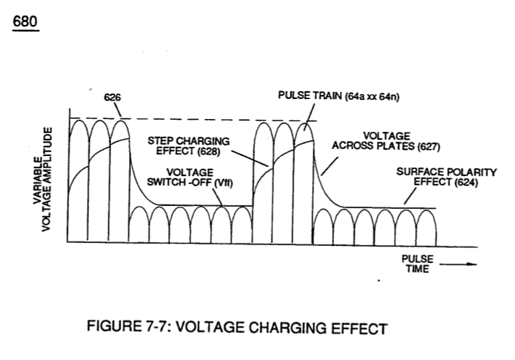
(627) of Figure (7-7) · Inductance Reactance (Rs - Cd - FL)
-
(750) of Figure (7-14) · Inductance Reactance (Rs - Cd - FL)
-
Figure (7-8) · Inductance Reactance (Rs - Cd - FL)
-
(620) of Figure (7-1) · Inductance Reactance (Rs - Cd - FL)
-
(580) of Figure (6-1) · Multi-layer Coil
-
The figure it sits on · Taper Resonant Capacitor (ERt)
-
(690) of Figure (7-8) · Taper Resonant Capacitor (ERt)
-
Resonant Capacitor (140 -170) of Figure (7-6) · Capacitance Reactance
-
(90) of Figure (5-5) · Capacitance Reactance
-
690 of Figure 7-8 · Circuit Resistance
-
Resonant Voltage Effect (670) of Figure (7-6) · Transformer Action
-
Choke-Coil (62) of Figure (7-1) · Transformer Action
-
(52) of Figure (7-8) · Electron Bounce Phenomenon
-
... causing "electron clustering" (641a xxx 641n) to take place within Copper Wire Zone (52) during pulse on- time (T1) · Electron Bounce Phenomenon
-
Voltage Graph (750) of Figure (7-14) · Electron Bounce Phenomenon
-
The figure it sits on · WFC 426 - Illustrations
-
The figure it sits on · WFC 426 - Illustrations
-
The figure it sits on · WFC 426 - Illustrations
-
The figure it sits on · WFC 426 - Illustrations
-
(580) of Figure (6-1) (WFC memo 425) · 8-2 - Traveling Voltage Wave-Guides
-
(780A) Figure (8-2) · 8-2 - Traveling Voltage Wave-Guides
-
(90) of Figure (5-5) · 8-2 - Traveling Voltage Wave-Guides
-
(690) of Figure (7-8) · 8-2 - Traveling Voltage Wave-Guides
-
Figure (8-2) · 8-2 - Traveling Voltage Wave-Guides
-
(52) of Figure (7-8) · 8-3 - Electrical Voltage-Pulse Wave-Transmission
-
(Cp) of Figure (7-8) · 8-4 - State Space (Sp)
-
(780 B) of Figure (8-2) · 8-4 - State Space (Sp)
-
(780 A/B/C) of Figure (8-2) · 8-4 - State Space (Sp)
-
Clipped Voltage Wave-form (780C) of Figure (8-2) · 8-5 - Energy Vectoring (Ev)
-
The figure it sits on · 8-6 - VIC Voltage Sync-Pulse Circuit
-
(620) of Figure (7-1) · 8-6 - VIC Voltage Sync-Pulse Circuit
-
(690) of Figure (7-8) · 8-6 - VIC Voltage Sync-Pulse Circuit
-
(Cp) of (7-8) · 8-6 - VIC Voltage Sync-Pulse Circuit
-
The figure it sits on · WFC 427 Illustrations
-
(690) of Figure (7-8) · Propagating Electrical Stress
-
"Resonant Charging Choke" (56) of Figure (7-1) · Propagating Electrical Stress
-
(580) of Figure (6-1) · Voltage to Amp Differential Ratio
-
Voltage Performance Graph (750) of Figure (7-14) · Voltage to Amp Differential Ratio
-
(620) of figure (7-1) · Voltage to Amp Differential Ratio
-
The figure it sits on · WFC 429 - Illustrations
Where it is named · 54
Electrically Charged Water Molecule 5×
-
water molecule atom (85)
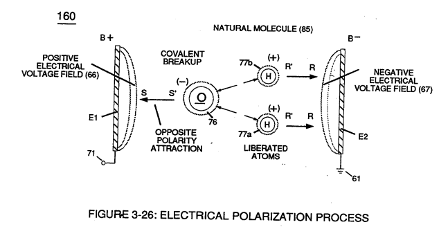
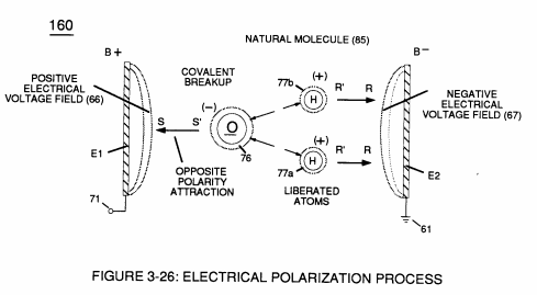
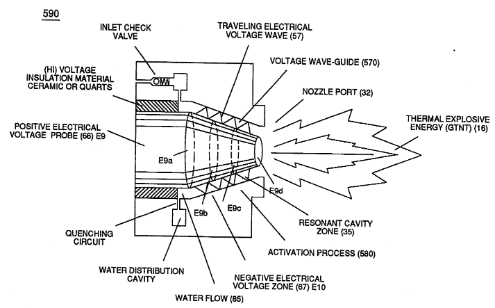
Voltage potential (65) within electrical circuit (60) can cause one or more electrons (79) to be dislodged from the water molecule atom (85) of Figure (3-26) due to opposite electrical polarity attraction (qq') of Figure (3-29) between unlike charged entities, as shown in (160) of Figure (326) as to Newton's and Coulomb's laws of electrical-force.
-
water (85)
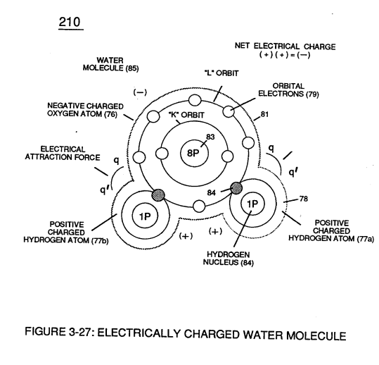
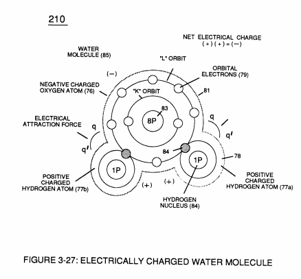
These same laws of electrical-force (qq') are used to combine or join atoms together by way of covalent bonding (opposite electrical forces) to form a molecule of water (85), as illustrated in (210) of Figure (3-27).
-
water molecule (85)
Together, the total net charge of water molecule (85) is zero despite the fact that each water molecule atom retains its electrical charge.
-
In other words, water molecule (85) is a electrically bipolar molecule having a stable configuration of charged atoms bound together by electrostatic force (qq').
-
water molecule (85)
… electromagnetic force is dependent on the movement of charged particles in a electrostatic field voltage Intensifier circuit (190) of figure (3-23), now, allows voltage to dissociates water molecule (85) by overcoming electrostatic bonding force (qq') between unlike atoms (76n7) while restricting amp flow, as illustrated in (160) of Figure (3-26).
Electrical Polarization process 3×
-
water molecule (85)
Once negative electrically charged oxygen atom (76) is dislodged from water molecule (85), covalent bonding (sharing electrons between atoms) ceases to exist, switching-off and disrupting electrical attraction force (qq') between unlike atoms (76/77), as further illustrated in (160) of Figure (3-26).
-
water molecules (85a xxx 85n)
Repetitive duplication of voltage pulse (65a xxx 65n) continues to separate or split apart other water molecules (85a xxx 85n) which, in turns, forms hydrogen (86) and oxygen (87) gas-mixture (88) of Figure (3-24).
-
water molecule (85)
Dissociation of water molecule (85) by way of voltage stimulation (65) is herein called "The Electrical Polarization Process", as illustrated in (160) of Figure (3-26).
Resonant Action 2×
-
water molecule (85)
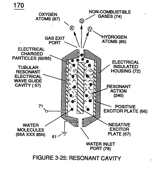
Subjecting and exposing water molecule (85) to even higher voltage levels (xxx Vn) (up to and beyond several thousand volts) causes water bath (91) of Figure (3-30) as to Figure (3-25) to go into a state of ionization by allowing opposite polarity forces (TT') and (UU') to eject one or more electrons (92a xxx 92n) from water bath atoms (93).
-
water molecules (85a xxx 85n)
Insulated housing (72) prevents voltage coupling to water bath (68) which allows applied voltage amplitude (xxx Vn) to remain constant across water molecules (85a xxx 85n)
Gas Modulator Process 1×
-
water bath (85)
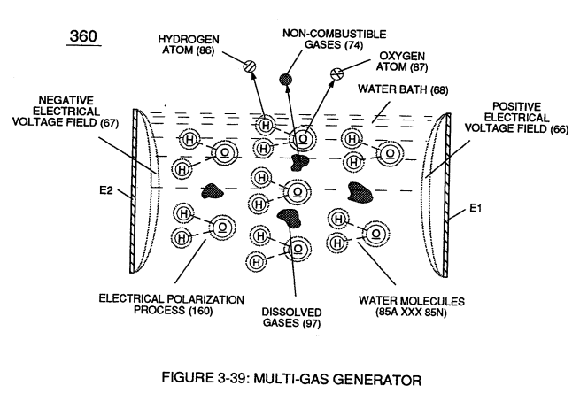
Dissolved air gases (97) of Figure (3-39) being uniformly released from water bath (85) via the Electrical Polarization Process (160) of Figure (3-26) is automatically intermixed with released hydrogen (86) and oxygen (87) gas atoms (also derived from water bath 85) to form Fuel-Gas mix …
Funneling Effect 9×
-
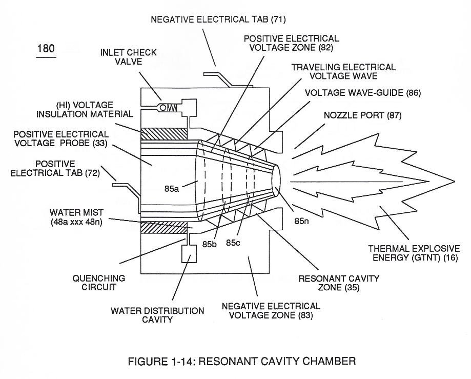
causing Resonant Cavity Zone (35) to function and perform as a voltage wave-guide (86) of Figure (14) since the gradual decrease in cross-sectional circumference area (85) of Figure (14) is in linear progression ... reducing both voltage surfaces areas (83/84) in parallel space relationship from larger segmental area (85a) to smaller segmental area (85n).
-
causing Resonant Cavity Zone (35) to function and perform as a voltage wave-guide (86) of Figure (14) since the gradual decrease in cross-sectional circumference area (85) of Figure (14) is in linear progression ... reducing both voltage surfaces areas (83/84) in parallel space relationship from larger segmental area (85a) to smaller segmental area (85n).
-
causing Resonant Cavity Zone (35) to function and perform as a voltage wave-guide (86) of Figure (14) since the gradual decrease in cross-sectional circumference area (85) of Figure (14) is in linear progression ... reducing both voltage surfaces areas (83/84) in parallel space relationship from larger segmental area (85a) to smaller segmental area (85n).
-
Start-Point (85a)
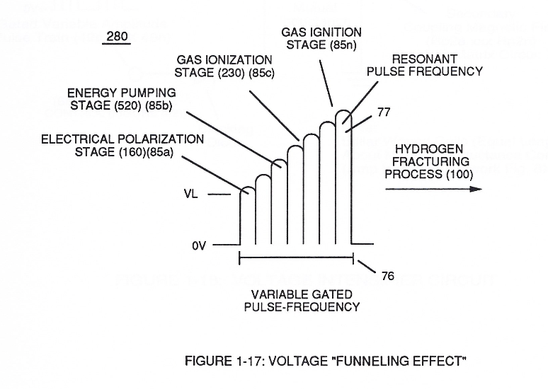
This resultant "Funneling Effect" (260), now, allows voltage amplitude (Vn) wave-form (58) to travel the length of Resonant Cavity Zone (35) from Start-Point (85a) to End-Point (85n) increasing voltage intensity (xxx VL = Vn) as parallel voltage surfaces (83/84) diminishes in size relationship (85a ~ 85n), as illustrated in (210) of Figure (17).
-
End-Point (85n)
This resultant "Funneling Effect" (260), now, allows voltage amplitude (Vn) wave-form (58) to travel the length of Resonant Cavity Zone (35) from Start-Point (85a) to End-Point (85n) increasing voltage intensity (xxx VL = Vn) as parallel voltage surfaces (83/84) diminishes in size relationship (85a ~ 85n), as illustrated in (210) of Figure (17).
-
Voltage amplitude level VL of Pulse-wave (58) is predetermined (20,000 V.D.C. typically) to start and cause Electrical Polarization Process (160) at a relative rapid rate of gas production at segmental point (85a) when voltage point (VL xx Va) is reached.
-
As voltage intensity increases (VL x Va x Vb) onward segmental point (85b), Energy Pumping Action (520) of Figure (4-3) (WFC Memo 424) as to (280) of Figure (34) (WFC Memo 422 DA) is activated to peak performance levels.
-
At segmental point (85c) voltage intensity (VL x Va x Vb x Vc) is increased sufficiently enough to propagate Gas Ionization Process (230) of Figure (3-30) (WFC Memo 422 DA).
-
At termination point (85), voltage intensity (VL x Va x Vb x Vc x Vn) is, now, increased to the point to cause Gas Ignition as Combustible Gas Atoms (76, 77a - 77b) which are, then, expelled from Gas Nozzle Port (87) of Figure (14) under dynamic pressure to allow thermal gas expansion (16) ... releasing thermal explosive energy (gtnt) beyond and away from Resonant Cavity Chamber (180), as illustrated in Figure (14).
In Application of Usage 2×
-
The Hydrogen Fracturing Process (390) of Figure (3-42) simply triggers and releases atomic energy (gtnt) from natural water (85) of Figure (3-26) by retarding and preventing the reformation of the water molecule being subjected to sub-critical state (520) of Figure (5-3) during thermal gas ignition (100) of Figure (4-8) as to (70) of Figure (4-5).
-
(85) of Figure (3-26)
Water Fuel Injector 2×
-
... dielectric value of water being 78.54 since water molecule (85) oxygen atom "L" orbit (76) occupies the maximum allowance eight electrons (79a xxx 79n), calibrated gated unipolar pulse train (64a xxx 64n) of Figure (3-20) is outputted from resonant choke (56) and electrically transmitted to positive outer conical surface (E9);
-
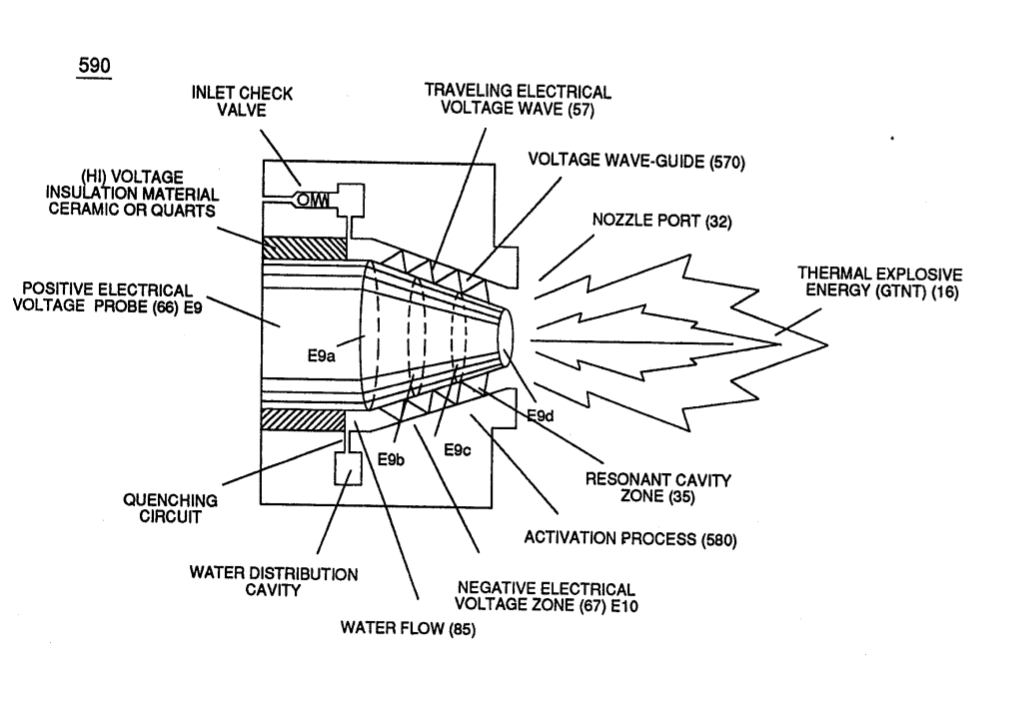
Activation point (E9a) exposes water flow (85) to voltage wave-form (64) of Figure (6-1) to begin water-to-energy conversion process (100);
Resistance (Rs) 3×
-
... releasing thermal explosive energy (gtnt) (16) of Figure (4-5) on demand from natural water (85) of Figure (3-26) since the dielectric value (Re) of (Eq.9) of Water Fuel (85) is further approximated in Capacitance Equation (Eq.22), as illustrated in (650) of Figure (7-4) as to Tapered Voltage Wave-Guide (720) of Figure (7-11)
-
Water Fuel (85)
... releasing thermal explosive energy (gtnt) (16) of Figure (4-5) on demand from natural water (85) of Figure (3-26) since the dielectric value (Re) of (Eq.9) of Water Fuel (85) is further approximated in Capacitance Equation (Eq.22), as illustrated in (650) of Figure (7-4) as to Tapered Voltage Wave-Guide (720) of Figure (7-11)
-
(85) of Figure (3-26)
Inductance (FL) 5×
-
Dielectric Water Bath (85/Re)
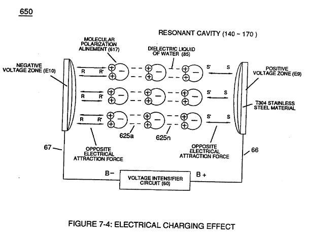
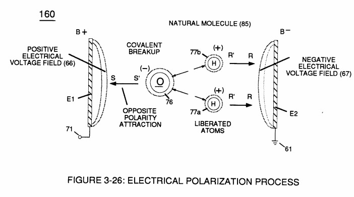
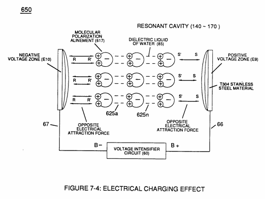
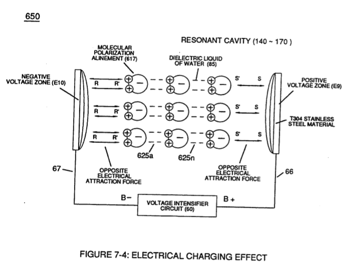
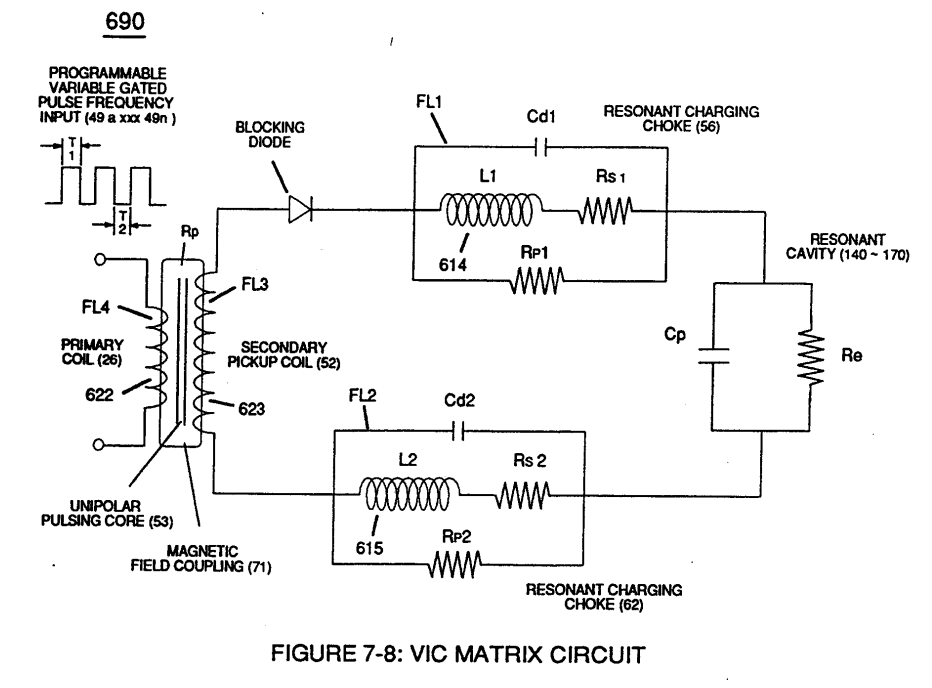
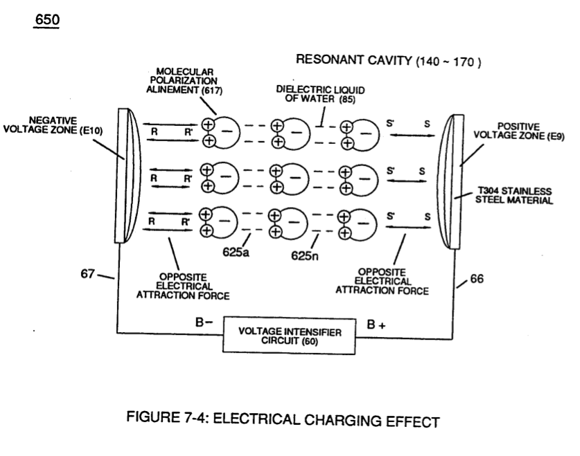
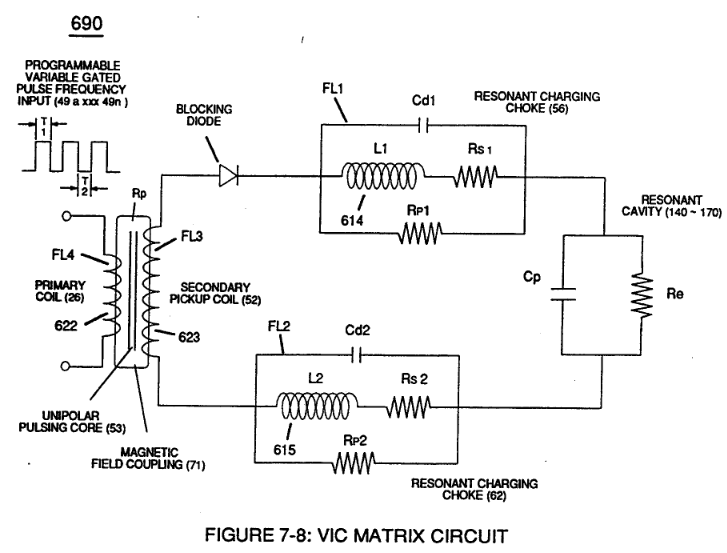
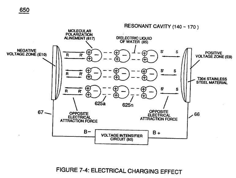
… 1) is formed when outer tapered surface (66) and inner tapered surface (67) forms Water-Gap (616) of Figure (7-11) as to Figure (590) of Figure (6-2) having placed there between Dielectric Water Bath (85/Re), as schematically illustrated in matrix outline in (670) of Figure (7-6) as to (690) of Figure (7-8) and further detailed in Electrical Charging Effect (650) of Figure (7-4).
-
... interacting Distributed Capacitance (Cda xxx Cdn) and Distributed Inductance (D1a xxx D1n) of Figure (7-3) of Inductor Coil (614) of (7-1) with "Electrical Charging Effect" brought on by the dielectric value of water bath (85/Re), as pictorially illustrated in (650) of Figure (7-4).
-
Dielectric Value of Water (85)
The established Dielectric Value of Water (85) being 78.54 ohms since the electron "L" orbit of the water molecule (210) of Figure (3-27) occupies the maximum allowable number of eight electrons when covalent linkup of 'unlike oxygen atom (76) and hydrogen atoms (77a/b) occurs' stabilizing Water molecule (85) into existence ... …
-
… molecule (210) of Figure (3-27) occupies the maximum allowable number of eight electrons when covalent linkup of 'unlike oxygen atom (76) and hydrogen atoms (77a/b) occurs' stabilizing Water molecule (85) into existence ... thereby, maintaining molecular stability of water by opposing the exchange of electrons from an external electron source (amp inducing circuit) beyond molecular Structure (85).
-
Structure (85)
… thereby, maintaining molecular stability of water by opposing the exchange of electrons from an external electron source (amp inducing circuit) beyond molecular Structure (85).
Capacitance (Cd) 5×
-
natural water (85)
Capacitor (E9/E10) of Figure (7-1) as to Figure (650) of Figure (7-4) in direct relationship to Water Gap (616) becomes Taper Resonant Cavity (720) of Figure (7-11) as shown in (590) of Figure (6-2) since Water Gap (616) is occupied by a dielectric liquid (Re) as herein before identified as natural water (85) having no electrolyte added thereto
-
rain water (85f)
... generally rain water (85f) (750) of Figure (7-14) being almost free of contaminates due to Water Evaporation Process (532) of Figure (5-6) ... rain water (850 being an liquid-insulator that restricts the flow of amps
-
water Molecule (85a - 85b - 85c - 85n)
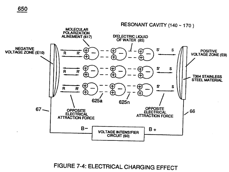
… Molecular Polarization Alignment (617) of Figure (7-4) by way of electrical molecular rotation (opposite electrical attraction force to rotate and position particle alignment) of each water Molecule (85a - 85b - 85c - 85n). being subjected to opposite electrical attraction forces (SS' - RR').
-
water (85)
Inherently, then, Resonant Cavity (720) of Figure (7-11) as to (650) of Figure (7-4) forms capacitor (ER) of Figure (7-1) when the dielectric liquid of water (85) is placed or injected between electrical conducting plates (E9/E10) while applied voltage Potential of opposite polarity (66/67) is directly exposed to Water Molecules (85a xxx 85n), as depicted in T …
-
Water Molecules (85a xxx 85n)
… dielectric liquid of water (85) is placed or injected between electrical conducting plates (E9/E10) while applied voltage Potential of opposite polarity (66/67) is directly exposed to Water Molecules (85a xxx 85n), as depicted in Taper Resonant Cavity (590) of Figure (6-2) as to (650) of Figure (7-4).
Inductance Reactance (Rs - Cd - FL) 1×
-
… ote "Electron Bounce" phenomenon (700) of Figure (7-9) while adjusting (programmable pulse wave-form) input signal Pulse-Frequency (49a xx 49n) to "tune-in" to the "dielectric property" (Re) of water (85) causing amp flow to be reduce to a minimum value while allowing voltage potential (627) of Figure (7-7) to go toward infinity if the electronic components would allow it to happen, as graphically ill …
In-Line Circuit Components 1×
-
Thermal Explosive Energy-Yield (gtnt) (16a xxx 16n) instantly produced from water (85) is determined by:
Taper Resonant Capacitor (ERt) 1×
-
Capacitance (Cp) of Figure (7-6) as to (690) of Figure (7-8) is determined by the surface area (A) of Electrical Voltage-Plates (E1/E2 - E9/E10), the distance (d) between the Electrical Plates (in inches), and the permittivity (Eo) of the dielectric property of water (85) and, is expressed in the following equation:
Circuit Resistance 1×
-
... each choke-coil (LIIL2) being of the same impedance value since both coil-wraps (56/62) are Bifilar wound together onto a single spool-bobbin, (Re) is the dielectric property of water and it's resistive value is typically (78.54 Q) since "rain water" (85f) contains less than 20ppm of any type of contaminates due to Water Evaporation Process (530) of Figure (5-6).

Electron Bounce Phenomenon 3×
-
Water (85)
... triggering Hydrogen Fracturing Process (90) of Figure (5-5) as to (100) of Figure (4-8) ... instantly releasing thermal explosive energy (gtnt) (16) from Water (85) on demand, as illustrated in Taper Resonant Cavity (590) of Figure (6-2) as to (70) of Figure (4-5).
-
... inhibiting "electron flow" to maintain opposite voltage potential (66/E9 _ 67/E10) across Resonant Water Gap (616) during the process of converting water-fuel (85) into instant thermal explosive energy (gtnt)
-
... therefore, producing a physical force-yield (Fy) during gas-ignition (70) of Figure (4-5) which is directly related to the liquid volume of water (85) per injection cycle and applied Resonant Voltage Intensity (Yo -Vn), as illustrated in (590) of Figure (6-2) as to (90) of Figure (5-5).
Mode of Operability 1×
-
Less water contaminants nets even higher energy-yield (gtnta xxx 85a - 85h xxx gtntn), as illustrated in Water Chart (760) of Figure (7-15).
8-2 - Traveling Voltage Wave-Guides 6×
-
injected water bath (85)
… having space-gap (35) there between and thus, fanning Cylindrical Resonant Cavity (730A) of Figure (7-12) as to (770A) of Figure (8-1) when space-gap (616) of Figure (720) exposes injected water bath (85) to unipolar pulse-oscillation of high voltage intensity of opposite polarity (67/66) as to (780) of Figure (8-2) which, in turn, propagates opposite electrical attraction force (RR' _ 88') of Figure …
-
The dielectric property of water (85) (resistance to electron flow) in conjunction with VIC Coil Matrix Circuit (690) of Figure (7-8) (WFC memo 426) as to VIC Coil Assembly (580) of Figure (6-1) (WFC memo 425) ability to inhibit amp "inf …
-
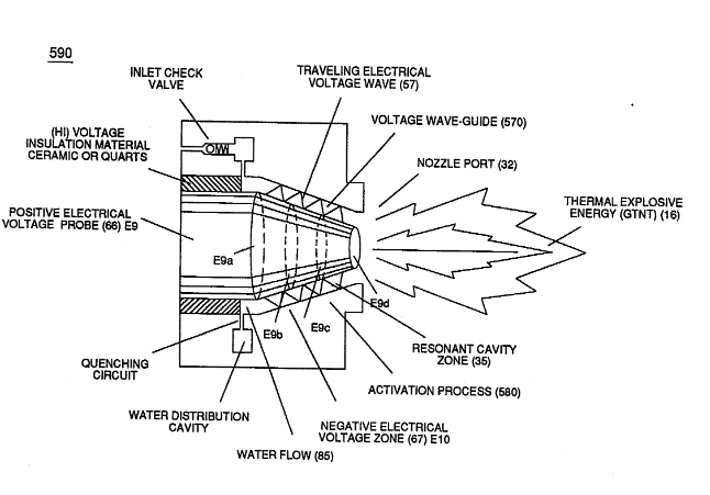
… ions (49a xx 49n) allows voltage amplitude of pulse-frequency potential (T1a xxxT1n) as to (Vo -64a-64b -64c - Vn) of (780A) Figure (8-2) to be applied across cross-sectional circular-ring water bath (85) (donut shape) to cause Voltage Wave-Form (57) of Figure (6-2) to travel the entire longitudinal length of water-gap (616) since stainless steel material (s/s) (T304) forming Voltage surfaces (E9/E1O) …
-
Water Bath (85)
...since Water Bath (85) is a dielectric-liquid (typically 78.54Q) that does not like to transfer nor exchange electrons
-
... allowing pulsating opposite electrical attraction forces (RR' / SS') to perform the work of "Electrically Charging" water bath (85) to bring-on and trigger Hydrogen Fracturing Process (90) of Figure (5-5), as illustrated in Energy Pumping stage (520) of Figure (5-3).
-
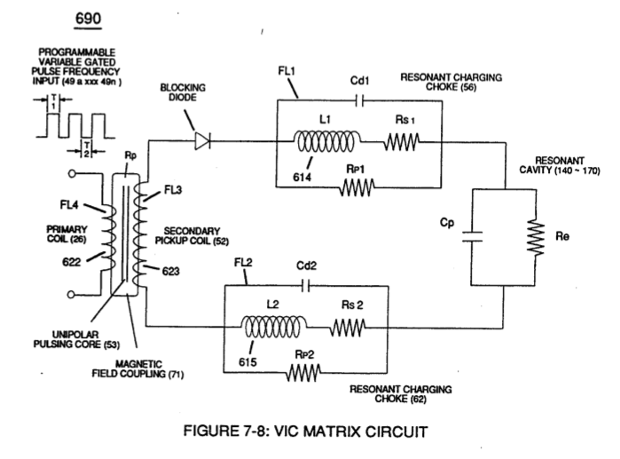
Voltage Intensifier Matrix Circuit (690) of Figure (7-8) electrically connected with resistive liquid (85/Re) (forming Resonant Water Gap "Cp" of Figure 7-8) propagates the transmission of Traveling Voltage Wave-Form (57) of Figure (6-2) as to (770) of Figure(8-1) by the functional relationship of Circuit Resistance Equation (Eq 9) during programmable Voltage Pulsing operations (49a xxx 1'3 xxx 49n) of Figure (8-2).
8-3 - Electrical Voltage-Pulse Wave-Transmission 1×
-
Water (85)
The newly established leading voltage edge (Vpa) and trailing voltage edge (Vpb) being uniform in shape/configuration since both Resonant Charging Chokes (56/Z2 – 62/Z3) resistive values are the same (Typically 11.6 kΩ each) and incoming signal (49a xxx 49n) is electrically linked with Water-Gap Capacitor (Cp) of Figure (7-8) having dielectric liquid of Water (85) there between.
8-4 - State Space (Sp) 1×
-
Generally speaking, Arc Curve (Vac) changing/varying to Arc-Line (Val) of Unipolar Voltage Pulse Wave-form (Vpwf) defines Voltage Pulse Field (Vpf) scan profile (Vsp) by which Trace-point "P" determines the type of "State Space" being used to propagate "Voltage Tickling" of water molecule (85) undergoing "Electrical Stress" under different fluid-pressures.
8-6 - VIC Voltage Sync-Pulse Circuit 1×
-
Water Molecule (85)
This non-voltage shift (Balanced Phasing of opposite Voltage Potential) helps prevents atom displacement during "Snapping-Action" by which "Resonant Electrical Stress" of opposite electrical polarity (RU/RU' - ST/ST') is applied equally across Water Molecule (s) (85) to propagate either Static (585) or Dynamic (612) Electrical Charging Effect (s) at elevated Voltage Peak Potential (s).