Figure (7-12)
Resonant Cavity Electrical Voltage Wave
How it is written
- (7-12) 22×
Drawings 9
-
(730) of Figure (7-12) · Taper Resonant Capacitor (ERt)
-
Traveling Electrical Voltage Wave-forms (730a - b - c) of Figure (7-12) · Electron Bounce Phenomenon
-
Compressional Wave-form (B) of Figure (7-12) · Voltage Amplitude Switch-Off
-
Captioned as this figure · Mode of Operability
-
(730A) of Figure (7-12) · 8-2 - Traveling Voltage Wave-Guides
-
(570) of Figure (7-12) · 8-2 - Traveling Voltage Wave-Guides
-
(730) of Figure (7-12) · 8-5 - Energy Vectoring (Ev)
-
(730C) of Figure (7-12) · 8-7 - Application of Usage
-
(730A) of Figure (7-12) · 8-7 - Application of Usage
On this figure 10
- 35 Resonant Cavity Zone
- 570 Voltage wave-guide
- 582 Flame-Front
- 730 Traveling Electrical Voltage Wave-forms
- 730A Cylindrical Resonant Cavity
- 730C Expanding Resonant Cavity
- 820A —
- E9 Capacitor
- E10 Capacitor
- Vn Voltage Potential
Where it is named · 22
Water Fuel Injector 1×
-
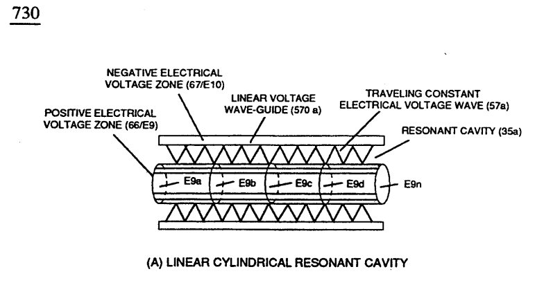
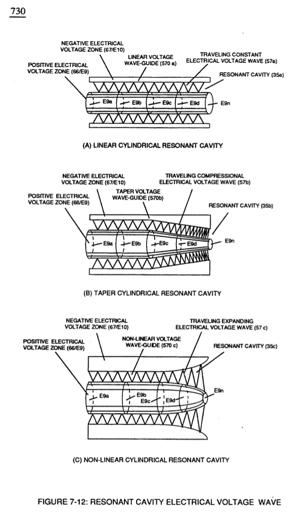
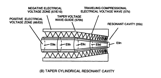
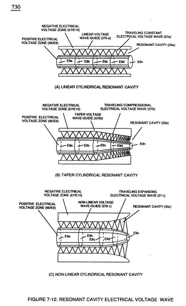
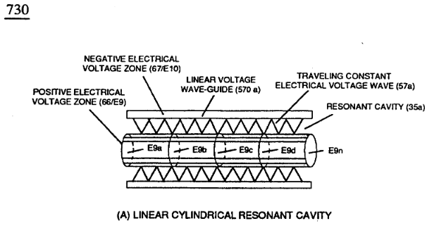
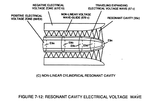
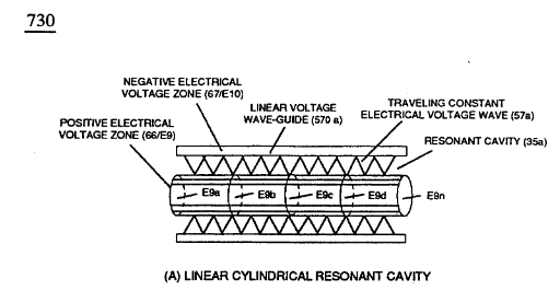
At each progressive point of diminishing circumference surface-area (E9a - b - c - d - E9n) voltage amplitude intensity increases (Vna - b - c - d - Vnn) uniformly, as illustrated in (600) of Figure (6-3) as to Travelling Voltage Wave-forms (730a - b - c) of Figure (7-12), see WFC Memo (426).
Taper Resonant Capacitor (ERt) 2×
-
(730) of Figure (7-12)
Capacitance Reactance 2×
-
Capacitor (ER) should remain relatively small due to the dielectric value of water to obtain maximum Thermal Explosive Energy-Yield (16a xxx 16n) of Figure (4-5) and subsequently establishing Quenching Circuit (370) of Figure (3-40) to prevent gas ignition inside traveling voltage wave-guide (590) of Figure (6-2) as to (730) of Figure (7-12)
-
(730) of Figure (7-12)
Electron Bounce Phenomenon 2×
-
Of course, in practical terms of component interaction, a minute amount of amp leakage is present and does occur due to Electronic Component Limitations but is negligible as to the overall performance of the Hydrogen Fracturing Process (590) of Figure (6-2) when being subjected to either one of Traveling Electrical Voltage Wave-forms (730 a-b-c) of Figure (7-12), see Voltage Graph (750) of Figure (7-14) once again.
-
Traveling Electrical Voltage Wave-forms (730a - b - c) of Figure (7-12)
Voltage Amplitude Switch-Off 2×
-
Voltage levels of variance (Va xxx Vn) is achieved by simply switching-in or switching-out the member of Secondary Coil-cavities (505a xx 505n) (see 740 of Figure 7-13) in direct relationship to Taper Resonant Voltage surfaces (E9/10) of Figure (6-2) which acts and performs as a "Voltage Amplifier" when Compressional Wave-form (B) of Figure (7-12) is intensified at Exit Port (32) of Figure (6-2).
-
Compressional Wave-form (B) of Figure (7-12)
Mode of Operability 1×
8-2 - Traveling Voltage Wave-Guides 5×
-
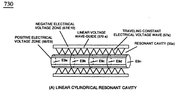
… parallel space relationship to form voltage surfaces (E9/E10) about an cylindrical axis of rotation having space-gap (35) there between and thus, fanning Cylindrical Resonant Cavity (730A) of Figure (7-12) as to (770A) of Figure (8-1) when space-gap (616) of Figure (720) exposes injected water bath (85) to unipolar pulse-oscillation of high voltage intensity of opposite polarity (67/66) as to (780) of …
-
(730A) of Figure (7-12)
-
(570) of Figure (7-12)
8-5 - Energy Vectoring (Ev) 2×
-
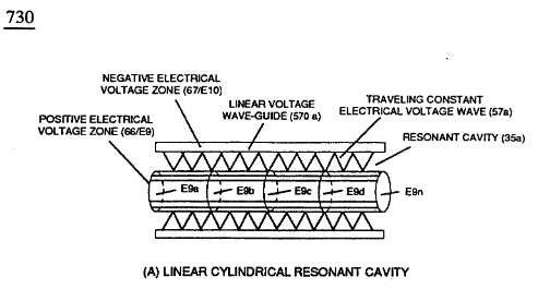
The "mode of operability" of determining the "Operational Parameters" of adjusting the thermal explosive energy (gtnt) exiting from nozzle-port (32) of Figure (4-5) as to (40) of Figure (4-2) is directly related to the characteristics of the applied Voltage Pulse Potential (Vpp) Wave-form (s) (Vpwt) and the geometrical configuration of Resonant Cavity (90) of Figure (4-7) as to (730) of Figure (7-12).
-
(730) of Figure (7-12)
8-7 - Application of Usage 4×
VIC Switchover Circuit 1×
-
In like manner as to linear cylindrical resonant cavity (730) of Figure (7-12), the Differential Voltage Wave-Guide (1040) of (1010) of Figure (11-1) as to Figure (11-6) is constructed in such a way as to allow a smaller tube to be placed inside a much larger tube having space relationship to allow water to pass there between, as so pictorially shown in (170) of Figure (3-25).