(590)
Taper Resonant Cavity
Also written Water Fuel Injection System · Activation Process · Hydrogen Fracturing Process
Where it is first named
… 424) titled "Atomic Energy Balance of Water" is further enhanced by simply electrically interfacing voltage intensifier (VIC) circuit coil-assembly (580) of Figure (6-1) with 'Taper Resonant Cavity" (590) of Figure (6-2), as schematically illustrated in (60) of Figure (3-22) as to pulse core configuration (190) of Figure (3-23) (Memo WFC 422 DA) titled "WFC Hydrogen Gas Management System.
How it is written
- (590) 23×
Drawings 16
-
(57) of Figure (6-2) · In Application of Usage
-
Activation Process (590) of Figure (6-2) · Voltage Intensifier Coil-Assembly
-
(590) of Figure (6-2) · Capacitance (Cd)
-
(E9/10) of Figure (6-2) · Voltage Amplitude Switch-Off
-
Water Fuel Injector Plug (40) of Figure (4-2) · Operational Parameters
-
(220) of Figure (18) · Water Fuel Injector (Taper Resonant Cavity Chamber)
-
The figure it sits on · Water Fuel Injector (Taper Resonant Cavity Chamber)
-
The Following Page 1-7 was not available · Water Fuel Injector (Taper Resonant Cavity Chamber)
-
Figure (4-2) · Water Fuel Injection System - Page 1
-
which simply uses Water Fuel Management (WFMS) System fluid-metering system (40) to control gas ignition (16), as illustrated in (40) of Figure (4-2). · Water Fuel Injection System - Page 4
-
(40) of Figure (4-2) · 8-5 - Energy Vectoring (Ev)
-
Figure (10-3 A/B) · Propagating Electrical Stress
-
The figure it sits on · WFC 429 - Illustrations
-
The figure it sits on · WFC 429 - Illustrations
-
The figure it sits on · WFC 429 - Illustrations
-
The figure it sits on · Wobbling Effect
Where it is named · 23
Water Fuel Injector 1×
-
Taper Resonant Cavity (590)
… 424) titled "Atomic Energy Balance of Water" is further enhanced by simply electrically interfacing voltage intensifier (VIC) circuit coil-assembly (580) of Figure (6-1) with 'Taper Resonant Cavity" (590) of Figure (6-2), as schematically illustrated in (60) of Figure (3-22) as to pulse core configuration (190) of Figure (3-23) (Memo WFC 422 DA) titled "WFC Hydrogen Gas Management System.
Taper Water Fuel Injectors 1×
-
Basically, then, activation process (590), now, design - forms Water Fuel Injector (20) of Figure (4-2) as to (30) of Figure (4-11) (Memo WFC 423 DA)
Voltage Intensifier Coil-Assembly 2×
-
Activation Process (590)
Activation Process (590) of Figure (6-2) as to (100) of Figure (4-8) is achieved since amp flow is restricted to enter into Voltage Triggering Process (70) of Figure (4-5) by way of voltage intensifier coil-assembly (580) of Figure (6-1).
Resistance (Rs) 1×
-
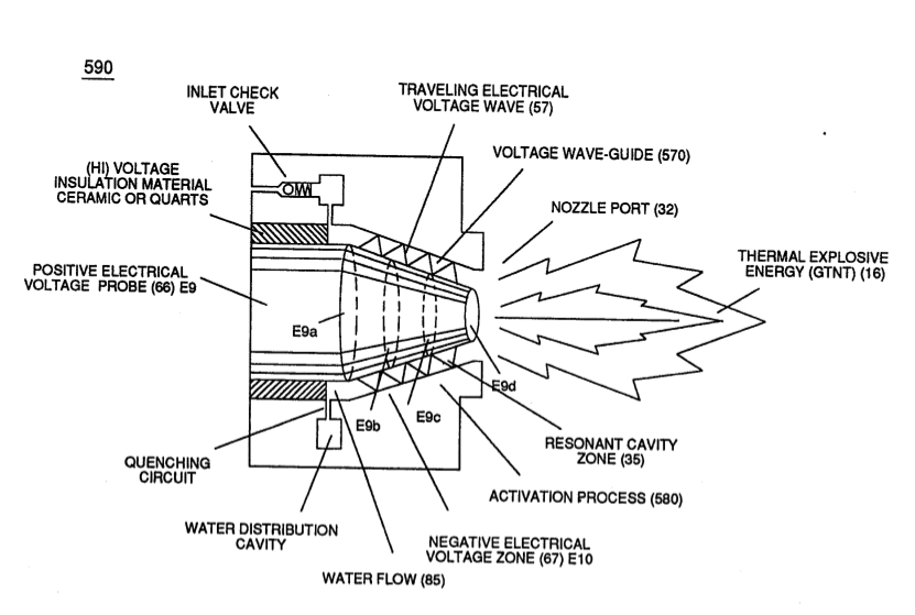
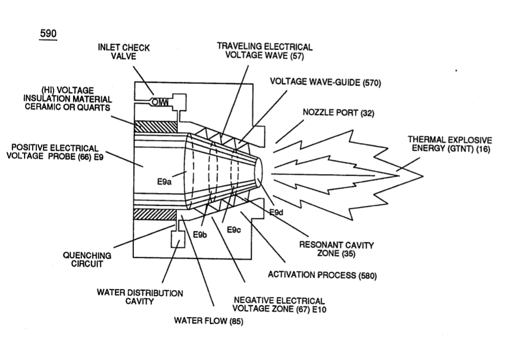
while, at the same time, conducting and permitting the transmission of "Voltage Potential" across circumference surface area (skin effect) (66/67) of Figure (7-11) as to Figure (590) of Figure (6-2) to bring-on and perform Voltage Wave-Guide phenomena (57) of Figure (6-2)
Inductance (FL) 1×
-
Capacitor (E9/E10) of figure (6-2) as to (720) of Figure (7-11) is formed when outer tapered surface (66) and inner tapered surface (67) forms Water-Gap (616) of Figure (7-11) as to Figure (590) of Figure (6-2) having placed there between Dielectric Water Bath (85/Re), as schematically illustrated in matrix outline in (670) of Figure (7-6) as to (690) of Figure (7-8) and further detailed in …
Capacitance (Cd) 4×
-
Capacitor (E9/E10) of Figure (7-1) as to Figure (650) of Figure (7-4) in direct relationship to Water Gap (616) becomes Taper Resonant Cavity (720) of Figure (7-11) as shown in (590) of Figure (6-2) since Water Gap (616) is occupied by a dielectric liquid (Re) as herein before identified as natural water (85) having no electrolyte added thereto
-
(590) of Figure (6-2)
-
Taper Resonant Cavity (590)
… d between electrical conducting plates (E9/E10) while applied voltage Potential of opposite polarity (66/67) is directly exposed to Water Molecules (85a xxx 85n), as depicted in Taper Resonant Cavity (590) of Figure (6-2) as to (650) of Figure (7-4).
-
(590) of Figure (6-2)
Capacitance Reactance 2×
-
Capacitor (ER) should remain relatively small due to the dielectric value of water to obtain maximum Thermal Explosive Energy-Yield (16a xxx 16n) of Figure (4-5) and subsequently establishing Quenching Circuit (370) of Figure (3-40) to prevent gas ignition inside traveling voltage wave-guide (590) of Figure (6-2) as to (730) of Figure (7-12)
-
(590) of Figure (6-2)
Electron Bounce Phenomenon 5×
-
Taper Resonant Cavity (590)
... triggering Hydrogen Fracturing Process (90) of Figure (5-5) as to (100) of Figure (4-8) ... instantly releasing thermal explosive energy (gtnt) (16) from Water (85) on demand, as illustrated in Taper Resonant Cavity (590) of Figure (6-2) as to (70) of Figure (4-5).
-
Taper Resonant Cavity (590)
Taper Resonant Cavity (590) of Figure (6-2)
-
... therefore, producing a physical force-yield (Fy) during gas-ignition (70) of Figure (4-5) which is directly related to the liquid volume of water (85) per injection cycle and applied Resonant Voltage Intensity (Yo -Vn), as illustrated in (590) of Figure (6-2) as to (90) of Figure (5-5).
-
(590) of Figure (6-2)
-
Hydrogen Fracturing Process (590)
Of course, in practical terms of component interaction, a minute amount of amp leakage is present and does occur due to Electronic Component Limitations but is negligible as to the overall performance of the Hydrogen Fracturing Process (590) of Figure (6-2) when being subjected to either one of Traveling Electrical Voltage Wave-forms (730 a-b-c) of Figure (7-12), see Voltage Graph (750) of Figure (7-14) once again.
8-2 - Traveling Voltage Wave-Guides 2×
-
… ation of high voltage intensity of opposite polarity (67/66) as to (780) of Figure (8-2) which, in turn, propagates opposite electrical attraction force (RR' _ 88') of Figure (7-4), as illustrated in (590) of Figure (6-2) as to (585) of Figure (8-1).
-
(590) of Figure (6-2)
8-7 - Application of Usage 2×
-
Taper Resonant Cavity (590)
For example, Taper Resonant Cavity (590) of Figure (6-2) as to (820B) of Figure (8-6) is ideally suited for internal combustion I. C. engines as well as Rocket Engines where high thrust-yield of explosive power (gtnt) (582B) is required;
-
(590) of Figure (6-2)
WFC Development Objectives 2×
-
Water Fuel Injection System (590)
The primary Purpose/objective of Water Fuel Injection System (590) of Figure (6-2) as to "FullSystem" development (10) of Figure (4-1) is, in the realm of scientific quest, to help reverse the damage being done to "Earth Ecological Life Support System" by first of all encouraging the use of "Water" as a new "Fuel" source
-
Water Fuel Injection System (590)
Water Fuel Injection System (590) of Figure (6-2)