(VIC)
Resonant Cavity Voltage Intensifier Circuit
Also written VIC Voltage Enhancement Circuit · Voltage Intensifier
Where it is first named
U.S. patent #4,826,581 issued May 2, 1989, Electrical Polarization Process U.S. Patent #4,936,961 issued Iune26, 1990, Resonant Cavity Voltage Intensifier Circuit (VIC) U.S. Patent 5,149,407 issued Sept 22, 1992, and other U.S. patents pending under the Patent Cooperation Treaty Act (PCT) Worldwide.
How it is written
- (VIC) 7×
- (VIC - VB) 2× with (Vb) VIC Voltage Enhancement Circuit
Drawings 43
-
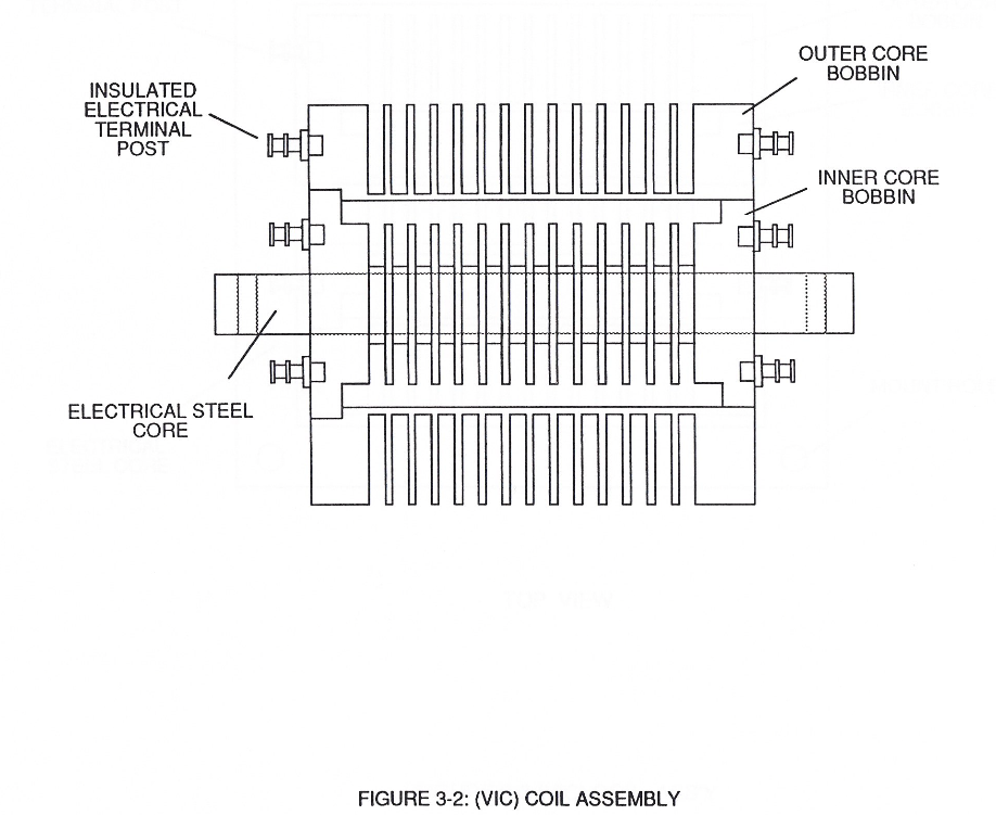
3-2 (VIC) Coil Assembly · Voltage Intensifier Coil Assembly
-
Carries this number · Electronic Circuit Design
-
Carries this number · Electronic Circuit Design
-
Carries this number · Electronic Circuit Design
-
Carries this number · Electronic Circuit Design
-
(220) of Figure (18) · Water Fuel Injector (Taper Resonant Cavity Chamber)
-
Carries this number · Water Fuel Injector (Taper Resonant Cavity Chamber)
-
coil-structures (580) of Figure (6-1) · Voltage Intensifier Coil-Assembly
-
(VIC) coil-assembly (530) of Figure (5-6) · Tri - Coil Construction
-
(580) of Figure (6-1) · Inductance (FL)
-
(580) of Figure (6-1) · Multi-layer Coil
-
(580) of Figure (6-1) (WFC memo 425) · 8-2 - Traveling Voltage Wave-Guides
-
(850) of Figure (8-11) · 8-6 - VIC Voltage Sync-Pulse Circuit
-
Carries this number · WFC 427 Illustrations
-
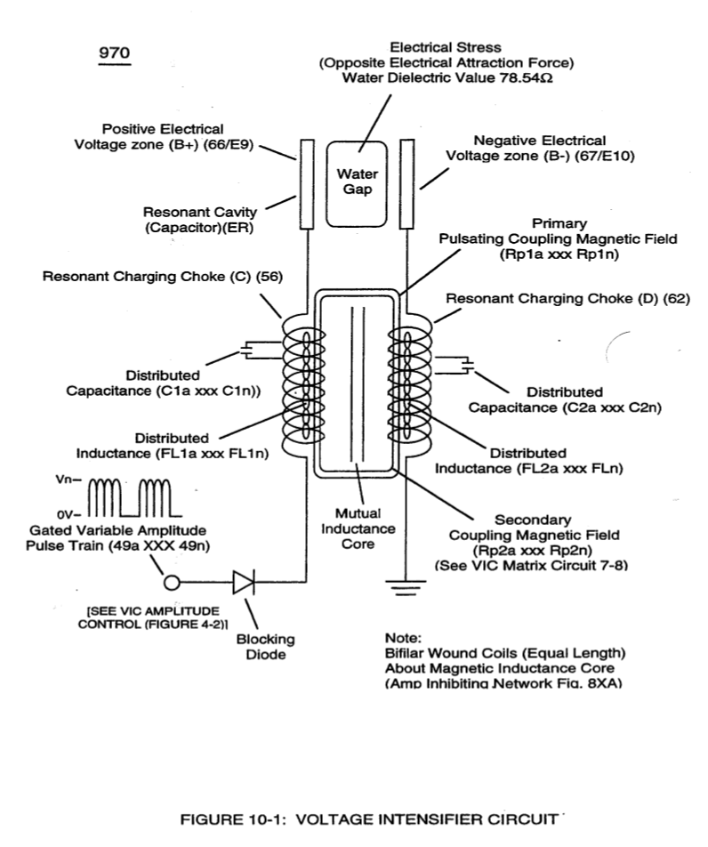
The programmable pulse-frequency (49a xxx 49n) of Figure (10-1) input is simply adjusted to tune-in to the dielectric property of the Water Molecule. · Propagating Electrical Stress
-
(580) of Figure (6-1) · Voltage to Amp Differential Ratio
-
Carries this number · WFC 429 - Illustrations
-
Carries this number · Wobbling Effect
-
(970) of Figure (10-1) · VIC Switchover Circuit
-
Figure (3-23) · Voltage Intensifier Circuit (60)
-
Figure (3-23) · Voltage Dynamics
-
The figure it sits on · WFC 422DA - Illustrations
-
The figure it sits on · Differential Air-Gas Inlet Control
-
...converts water mist (68) into it's component gases hydrogen (77 a/b) oxygen (76) and ambient air gases (97); · Triggering Process
-
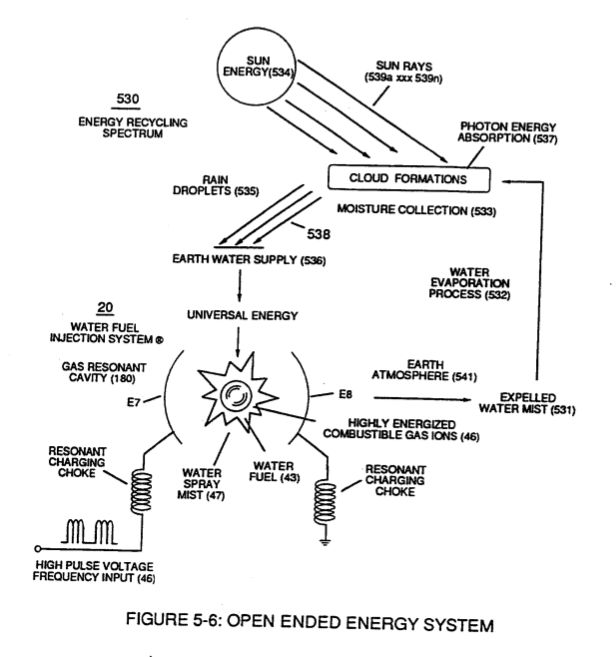
Figure (5-6) · Energy Recycling Spectrum
-
(190) of Figure (3-23) · Tri - Coil Construction
-
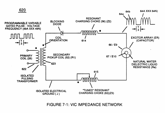
Voltage Intensifier Circuit (620) of Figure (7-1) · Instant Explosion of Water
-
(620) of Figure (7-1) · Instant Explosion of Water
-
(620) of Figure (7-1) · Resistance (Rs)
-
(614) of Figure (7-1) · Inductance (FL)
-
Inductor (614) of Figure (7-1) · Inductance (FL)
-
(614) of (7-1) · Inductance (FL)
-
(532) of Figure (5-6) · Capacitance (Cd)
-
Figure (7-1) · Capacitance (Cd)
-
Inductance Pulsing-Core (190) of Figure (3-23) · Inductance Reactance (Rs - Cd - FL)
-
(620) of Figure (7-1) · Inductance Reactance (Rs - Cd - FL)
-
Choke-Coil (62) of Figure (7-1) · Transformer Action
-
The figure it sits on · Electron Bounce Phenomenon
-
The figure it sits on · WFC 426 - Illustrations
-
(620) of Figure (7-1) · 8-6 - VIC Voltage Sync-Pulse Circuit
-
"Resonant Charging Choke" (56) of Figure (7-1) · Propagating Electrical Stress
-
(620) of figure (7-1) · Voltage to Amp Differential Ratio
-
Differential Voltage Wave-Guild (1040B) · Electrical Crossover Switching Circuit
Where it is named · 9
In Summation 1×
-
Resonant Cavity Voltage Intensifier Circuit (VIC)
U.S. patent #4,826,581 issued May 2, 1989, Electrical Polarization Process U.S. Patent #4,936,961 issued Iune26, 1990, Resonant Cavity Voltage Intensifier Circuit (VIC) U.S. Patent 5,149,407 issued Sept 22, 1992, and other U.S. patents pending under the Patent Cooperation Treaty Act (PCT) Worldwide.
Voltage Intensifier Coil Assembly 1×
-
3-2 (VIC) Coil Assembly
Water Fuel Injector 1×
-
… of opposite electrical polarity (ST - ST' - RU - RU') of Figure (5-1) (Memo WFC 424) titled "Atomic Energy Balance of Water" is further enhanced by simply electrically interfacing voltage intensifier (VIC) circuit coil-assembly (580) of Figure (6-1) with 'Taper Resonant Cavity" (590) of Figure (6-2), as schematically illustrated in (60) of Figure (3-22) as to pulse core configuration (190) of Figure (3 …
Tri - Coil Construction 3×
-
Resonant bobbin assembly (503), primary bobbin assembly (504), and secondary bobbin assembly (506), now, make up and structurally forms voltage intensifier (VIC) coil-assembly (530) of Figure (5-6) when electrical steel core material (53) forms a close-loop magnetic induction pathway centrally through and around (VIC) coil-assembly (530), as schematically illustrated in (190) of Figure (3-23) (Memo WFC 422 DA).
-
Resonant bobbin assembly (503), primary bobbin assembly (504), and secondary bobbin assembly (506), now, make up and structurally forms voltage intensifier (VIC) coil-assembly (530) of Figure (5-6) when electrical steel core material (53) forms a close-loop magnetic induction pathway centrally through and around (VIC) coil-assembly (530), as schematically illustrated in (190) of Figure (3-23) (Memo WFC 422 DA).
-
(VIC) coil-assembly (530) of Figure (5-6)
Instant Explosion of Water 2×
-
VIC Voltage Enhancement Circuit (VIC - VB)
VIC Voltage Enhancement Circuit (VIC - VB) (620) of Figure (7-1) incorporates the use of stainless steel wire-wrap coils (614/615) to accomplish the formation of unipolar gated pulse-wave (64a xxx T3 xxx 64n) without experiencing "signal dist …
-
(VIC - VB) (620) of Figure (7-1)
VIC Switchover Circuit 1×
-
Voltage Intensifier (VIC)
Electrically energizing Voltage Intensifier (VIC) Circuit (1002), now, causes both bipolar water molecules (1004/1006) to be deflected and displaced in a left-hand movement, as so illustrated in (1030) of Figure (11-4).