Figure (8-2)
Programmable Voltage Pulse-wave
How it is written
- (8-2) 18×
Drawings 7
-
(780A) Figure (8-2) · 8-2 - Traveling Voltage Wave-Guides
-
Figure (8-2) · 8-2 - Traveling Voltage Wave-Guides
-
(780 B) of Figure (8-2) · 8-4 - State Space (Sp)
-
(780 A/B/C) of Figure (8-2) · 8-4 - State Space (Sp)
-
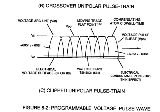
Clipped Voltage Wave-form (780C) of Figure (8-2) · 8-5 - Energy Vectoring (Ev)
-
Captioned as this figure · 8-6 - VIC Voltage Sync-Pulse Circuit
-
Captioned as this figure · WFC 427 Illustrations
On this figure 26
- 49 Voltage Pulse frequency
- 64 Pulse Train
- 66 Positive Voltage Potential
- 67 Opposite Polarity
- 85 Water Molecule
- 583 Voltage Pulse Train
- 585 Static Electrical Charging Effect
- 602 Voltage Pulse Train
- 605 clipped Voltage Pulse Train
- 606 clipped Voltage Pulse Train
- 607 Crossover Unipolar Pulse Train
- 608 Crossover Unipolar Pulse Train
- 609 Progressive Voltage Sync-Wave
- 611 Progressive Voltage Sync-Wave
- 616 Water Gap
- 690 VIC Matrix Circuit
- 720 Taper Resonant Cavity
- 780 —
- 780A Planar Unipolar Pulse Train
- 780B Convergent Point "Q"
- 780C Clipped Unipolar Pulse Train
- Est Electrical Stress Force
- Pwf Pulse Wave Frequency
- Vn Voltage Potential
- Vo Applied Voltage Amplitude
- Vpp Voltage Peak Potential
Where it is named · 18
8-2 - Traveling Voltage Wave-Guides 6×
-
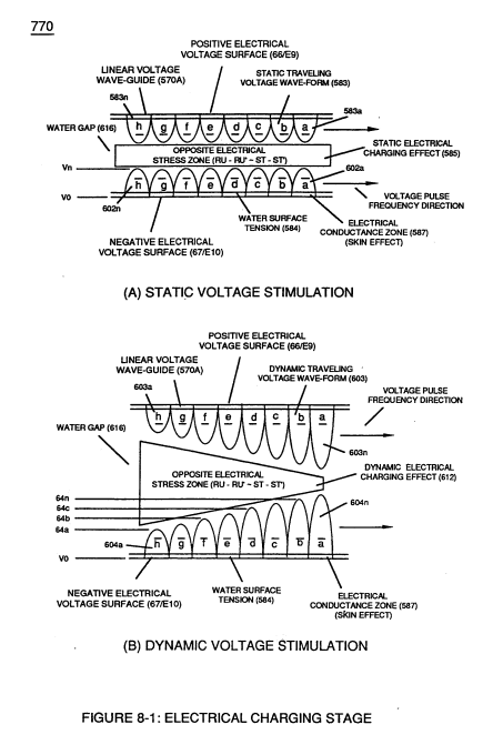
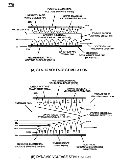
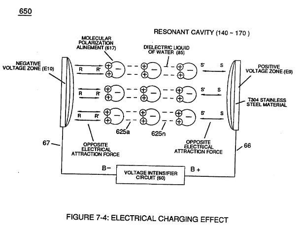
… (770A) of Figure (8-1) when space-gap (616) of Figure (720) exposes injected water bath (85) to unipolar pulse-oscillation of high voltage intensity of opposite polarity (67/66) as to (780) of Figure (8-2) which, in turn, propagates opposite electrical attraction force (RR' _ 88') of Figure (7-4), as illustrated in (590) of Figure (6-2) as to (585) of Figure (8-1).
-
(780) of Figure (8-2)
-
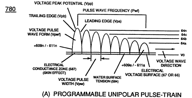
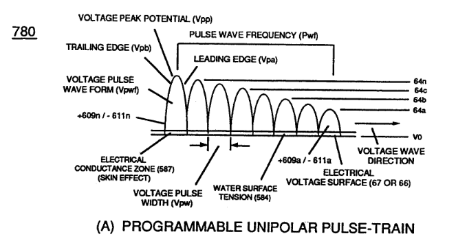
… p "influxing" (Electron Bounce Phenomenon EbP) during pulsing operations (49a xx 49n) allows voltage amplitude of pulse-frequency potential (T1a xxxT1n) as to (Vo -64a-64b -64c - Vn) of (780A) Figure (8-2) to be applied across cross-sectional circular-ring water bath (85) (donut shape) to cause Voltage Wave-Form (57) of Figure (6-2) to travel the entire longitudinal length of water-gap (616) since stai …
-
(780A) Figure (8-2)
-
Voltage Intensifier Matrix Circuit (690) of Figure (7-8) electrically connected with resistive liquid (85/Re) (forming Resonant Water Gap "Cp" of Figure 7-8) propagates the transmission of Traveling Voltage Wave-Form (57) of Figure (6-2) as to (770) of Figure(8-1) by the functional relationship of Circuit Resistance Equation (Eq 9) during programmable Voltage Pulsing operations (49a xxx 1'3 xxx 49n) of Figure (8-2).
-
Figure (8-2)
8-4 - State Space (Sp) 5×
-
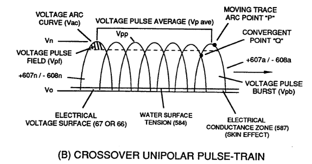
Electrical Attraction Force intensity (RR' - SS' as to RU/RU' - ST/ST' as to 550 of Figure 5-8) at Peak Voltage Potential (Vpp) is either increasing or decreasing or remaining constant as to Voltage Peak Excursion Point "P" trace-position which scans the exact Pulse Wave-Form (66- 583/67-602) being produced, as illustrated in (780B) of Figure (8-2).
-
(780 B) of Figure (8-2)
-
… Wave-form (Vcwf) during Voltage Pulse Shaping by way of Programmable Pulsing Circuit (WFC project 422DA/423DA) electrically interfaced with VIC Matrix Circuit (690), as illustrated in (780) of Figure (8-2).
-
(780 A/B/C) of Figure (8-2)
-
… osite Attraction Force (RR' -SS') to remain at constant electrical intensity (RR' - SS' cei) when Peak Voltage Potential (Vpp) is clipped in forming Arc-Line (Val), as illustrated in (780C) of Figure (8-2).

8-5 - Energy Vectoring (Ev) 4×
-
Static State Space (Sss) is the electrical condition by which Electrical Attraction Force (RR' - SS' as to RU/RU' - ST/ST') is being held constant once Voltage Pulse Burst Vpb) occurs during Voltage Pulsing Operation (Vpwf) ... forming synchronized Clipped Voltage Wave-form (780C) of Figure (8-2) in like manner to voltage sync-pulse (583 - 602).
-
Clipped Voltage Wave-form (780C) of Figure (8-2)
-
… a of Voltage Sync-Wave (+/-) propagation, Unipolar Voltage Pulse Train (583/602a xxx 583/602) of (770A) of Figure (8-1), clipped Voltage Pulse Train (605/606a xxx 605/606n) of Figure (780C) of Figure (8-2), and Crossover Unipolar Pulse Train (607/608a xxx 607/608n) brings-on Static Voltage Stimulation (Vsvs) by which Static Electrical Charging Effect (585) is being held constant since Electrical Stress …
-
On the other hand, Progressive Voltage Sync-Wave (+609 / - 611) (609/611a xxx 609/611n) of Figure (780A) of Figure (8-2) encourages Dynamic Voltage Stimulation (Dvs) since Voltage Peak Potential (Vpp) increases as Voltage Sync-Wave Front (a to b to c and so on) advances in the number of Unipolar Voltage Pulse (s) (Vwp), as illustrated in Figure (3-21) ... …
8-6 - VIC Voltage Sync-Pulse Circuit 2×
-
Voltage Sync-Pulse Gated Frequency (583/602a xxx 583/602n) (603/604a xxx 603/604n) of Figure (8-1) as to (605/606a xxx 605/606n) (607/608a xxx 607/608n) (609/611a xxx 609/611n) of Figure (8-2)
-
… nd maintain Capacitance Charging Effect (650) of Figure (7-4) across Water-Gap (Cp) of (7-8) during applied pulsing operations (49a xxx 49n), Crossover Voltage Wave-Form (780B) as to (780C) of Figure (8-2) is generally utilized by not allowing Convergent Point "Q" of Figure (780B) to reach Electrical Ground Point (0V) when each Unipolar Voltage Pulse (Vpp) is electrical energized in phase-distance rela …
Quartz Tube Configuration & Operational Parameters 1×
-
... forming Pulse Wave Frequency (Pwf), as so illustrated in (780) of Figure (8-2) as to (770) of Figure (8-1).