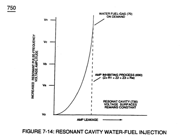
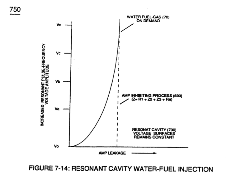
Figure (7-14)
Resonant Cavity Water-fuel Injection
How it is written
- (7-14) 13×
Drawings 6
-
(750) of Figure (7-14) · Inductance (FL)
-
(750) of Figure (7-14) · Capacitance (Cd)
-
(750) of Figure (7-14) · Inductance Reactance (Rs - Cd - FL)
-
Voltage Graph (750) of Figure (7-14) · Electron Bounce Phenomenon
-
Captioned as this figure · WFC 426 - Illustrations
-
Voltage Performance Graph (750) of Figure (7-14) · Voltage to Amp Differential Ratio
On this figure 4
Where it is named · 13
Voltage Intensifier Coil-Assembly 1×
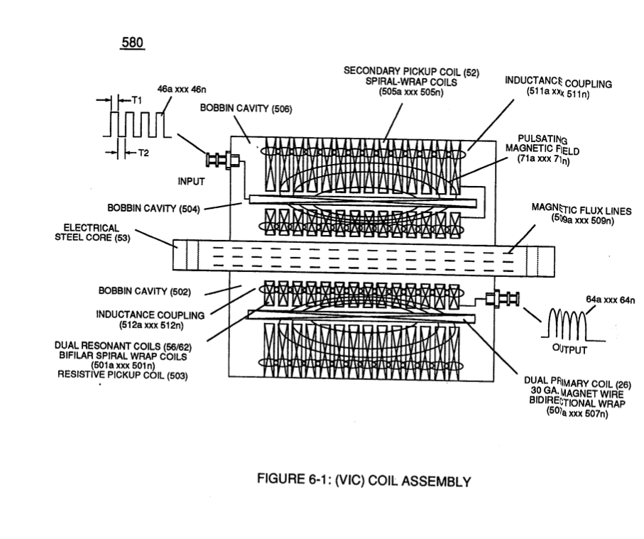
Inductance (FL) 2×
-
(750) of Figure (7-14)
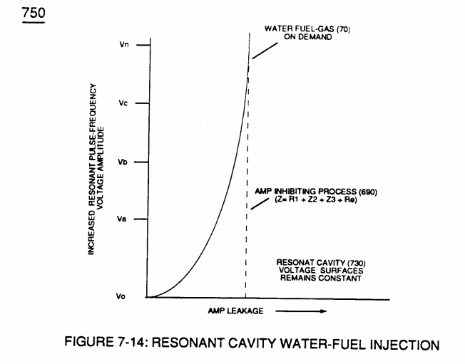
Capacitance (Cd) 2×
-
(750) of Figure (7-14)
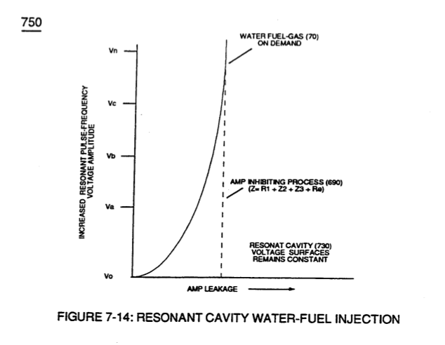
Inductance Reactance (Rs - Cd - FL) 3×
-
(750) of Figure (7-14)
Electron Bounce Phenomenon 2×
-
Of course, in practical terms of component interaction, a minute amount of amp leakage is present and does occur due to Electronic Component Limitations but is negligible as to the overall performance of the Hydrogen Fracturing Process (590) of Figure (6-2) when being subjected to either one of Traveling Electrical Voltage Wave-forms (730 a-b-c) of Figure (7-12), see Voltage Graph (750) of Figure (7-14) once again.
-
Voltage Graph (750) of Figure (7-14)
Propagating Electrical Stress 1×
Voltage to Amp Differential Ratio 2×
-
keeping amp-surge (inhibiting amp flow) to a minimal level [See Voltage Performance Graph (750) of Figure (7-14)] while enhancing Voltage Potential of Electrical Stress (64/RU-RU'a xxx 64/ST-ST'n) as additional Dual Choke Coils (56/62 _ SS56/62) are included in the stacked coil-array forming Voltage Intensifier Circuit (970) of Figure (10-1) as to (620) of figure (7-1)
-
Voltage Performance Graph (750) of Figure (7-14)