(770)
Static Voltage Stimulation
Also written Dynamic Voltage Stimulation · Traveling Voltage Wave-Action · Dynamic Voltage Waveform · Voltage Wave-Guides
Where it is first named
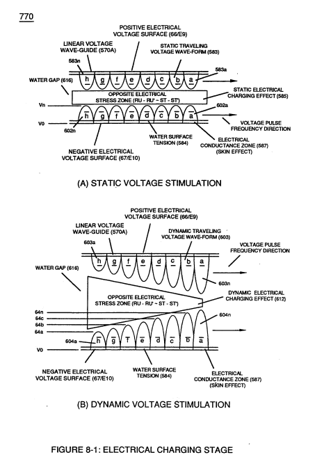
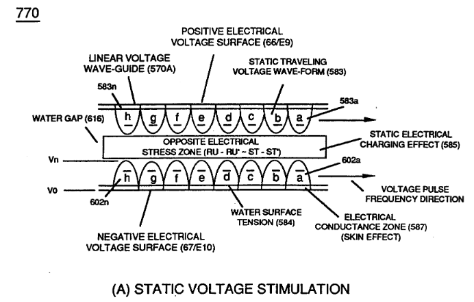
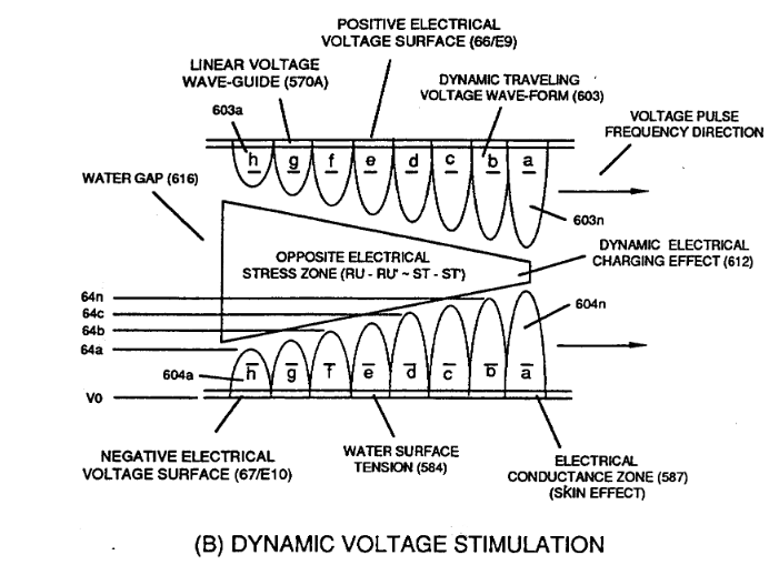
The formation of tubular Traveling Voltage Wave-guide (570a) of Figure (7-12) (WFC Memo 426) as to (770) of Figure (8-1) is physically formed when positive electrical voltage surface (66/E9) and negative electrical voltage surface (67/E10) are placed in parallel space relationship to form voltage surfac …
How it is written
- (770) 16×
- (770 A) 1× with (770A) Voltage Tickling of State Space
- (770 A/B) 1× with (770A) Voltage Tickling of State Space, (770B) Stimulation
- (770 B) 1× with (770B) Stimulation
Drawings 15
-
(770) of Figure(8-1) · 8-2 - Traveling Voltage Wave-Guides
-
(770) of Figure (8-1) · 8-3 - Electrical Voltage-Pulse Wave-Transmission
-
(770 A) of Figure (8-1) · 8-4 - State Space (Sp)
-
(770 B) of Figure (8-1) · 8-4 - State Space (Sp)
-
(770A) of Figure (8-1) · 8-5 - Energy Vectoring (Ev)
-
Carries this number · 8-6 - VIC Voltage Sync-Pulse Circuit
-
Carries this number · WFC 427 Illustrations
-
"Voltage Tickling of State Space" (770A) of Figure (8-1) · WFC Exhaust Air Reclaimer
-
... see Dynamic Voltage Waveform (770) of Figure (8-1), once again. · Voltage to Amp Differential Ratio
-
Carries this number · Quartz Tube Configuration & Operational Parameters
-
Carries this number · Quartz Tube Configuration & Operational Parameters
-
(585) of Figure (8-1) · 8-4 - State Space (Sp)
-
(612) of Figure (8-1) · 8-5 - Energy Vectoring (Ev)
-
"Voltage Tickling of State Space" (770B) of Figure (8-1) · WFC Exhaust Air Reclaimer
-
... establishing variable Dynamic Electrical Charging Effect (612). · Quartz Tube Configuration & Operational Parameters
Where it is named · 19
8-2 - Traveling Voltage Wave-Guides 4×
-
The formation of tubular Traveling Voltage Wave-guide (570a) of Figure (7-12) (WFC Memo 426) as to (770) of Figure (8-1) is physically formed when positive electrical voltage surface (66/E9) and negative electrical voltage surface (67/E10) are placed in parallel space relationship to form voltage surfac …
-
(770) of Figure (8-1)
-
Voltage Intensifier Matrix Circuit (690) of Figure (7-8) electrically connected with resistive liquid (85/Re) (forming Resonant Water Gap "Cp" of Figure 7-8) propagates the transmission of Traveling Voltage Wave-Form (57) of Figure (6-2) as to (770) of Figure(8-1) by the functional relationship of Circuit Resistance Equation (Eq 9) during programmable Voltage Pulsing operations (49a xxx 1'3 xxx 49n) of Figure (8-2).
-
(770) of Figure(8-1)
8-3 - Electrical Voltage-Pulse Wave-Transmission 2×
-
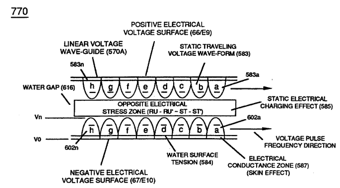
… 9) which, inactivated electrical-state, allows positive Voltage Pulse-Wave (583) to be duplicated in succession to form Voltage Pulse Train (66 - 583a xxx 583n), as illustrated in (770) of Figure (8-1).
-
(770) of Figure (8-1)
8-4 - State Space (Sp) 3×
-
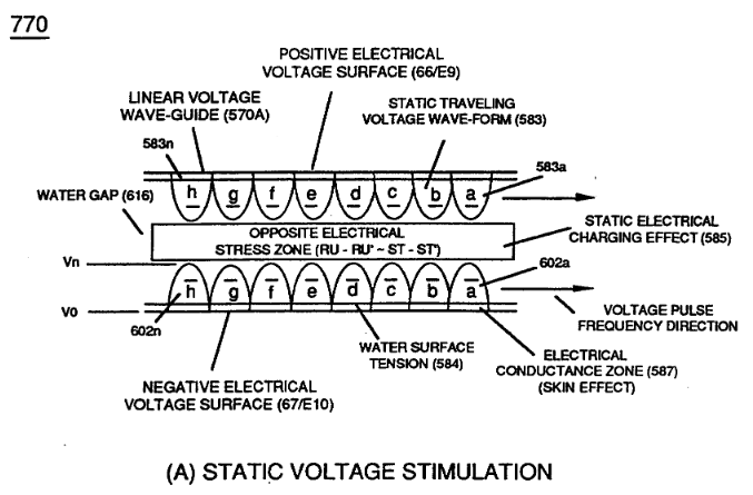
During the electrical-formation (66- Vpa/Vpb - 67- Vpa/Vpb) of each opposite Electrical Voltage-Wave (66-583 - 67-602), opposite electrical attraction force (RR' - SS') of Figure (7-4) is produced across water cap (Cp) of Figure (7-8) which, now, sets up and defines the conditions of “State Space," as illustrated in (770 A/B) of Figure (8-1) as to (650) of Figure (7-4).
-
(770 A) of Figure (8-1)
-
(770 B) of Figure (8-1)
8-6 - VIC Voltage Sync-Pulse Circuit 1×
-
Traveling Voltage Wave-Action (770)
... all, forming Voltage Pulse Burst Wave (619) as to Unipolar Pulse-Train (780A), Crossover Unipolar Pulse-Train (780B), and Clipped Unipolar Pulse Train (780C) as to Traveling Voltage Wave-Action (770) of Figure (8-1) of opposite voltage polarity (+/-) of equal Voltage-Pulse Amplitudes (+Vpp/- Vpp) are zero reference to electrical ground state (0V) by placing Amp Inhibitor Circuit (860) (Amp Inhibi …
Voltage to Amp Differential Ratio 1×
-
Dynamic Voltage Waveform (770)
... see Dynamic Voltage Waveform (770) of Figure (8-1), once again.
Optical Thermal Lens 1×
-
Voltage Wave-Guides (770)
The Vacuum Chamber (Cv) containing the hydrogen gas atoms is composed of a high temperature quartz material (918) while Voltage Zones (ER) becomes Voltage Wave-Guides (770) of Figure (8-1) by the use of chemically inert T304 stainless steel material
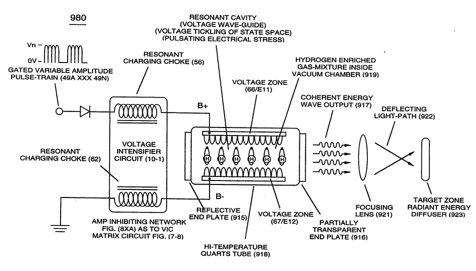
Quartz Tube Configuration & Operational Parameters 7×
-
Static Voltage Stimulation (770)
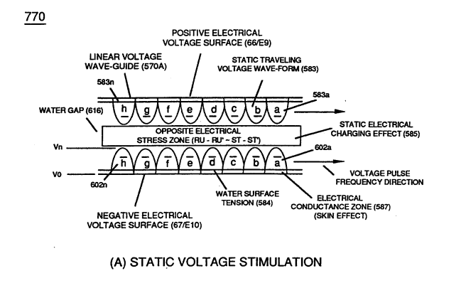
Exposing the hydrogen atoms to applied Static Voltage Stimulation (770) of Figure (8-1) causes the Static Electrical Charging Effect (585) to set up "Voltage Tickling of State Space" which takes the hydrogen atom (s) from "Quiescent State" (Qs) to "Active State" (As) and …
-
... forming Pulse Wave Frequency (Pwf), as so illustrated in (780) of Figure (8-2) as to (770) of Figure (8-1).
-
Static Voltage Stimulation (770)
Static Voltage Stimulation (770) of Figure (8-1A) is where Voltage Peak Potential (Vpp) remains constant during Voltage Pulse Formation (VpbNpa) to keep reforming Flex-Density Potential (Fdpa xxx Fdpn) from going beyond a certain point away from Static State of Equilibrium (Esse)
-
Dynamic Voltage Stimulation (770)
Dynamic Voltage Stimulation (770) of Figure (8-1B) continues to go farther and farther away from the State of Equilibrium (Esse) during each and every Voltage Pulsing Cycle (Vpf), as so illustrated in (770) of Figure (8-1B}
-
Dynamic Voltage Stimulation (770) of Figure (8-1B) continues to go farther and farther away from the State of Equilibrium (Esse) during each and every Voltage Pulsing Cycle (Vpf), as so illustrated in (770) of Figure (8-1B}
-
Static Voltage Stimulation (770)
In both cases, Static Voltage Stimulation (770) of Figure (8-1A) and Dynamic Voltage Stimulation (770) of Figure (8-1B) incorporates the use of Positive Electrical Voltage Potential (B+) (Ell) and Negative Electrical Voltage Potential (B-) (EI2) to form synchronized diametrically opposed Voltage Gate-Pulse (Vgp) (583/602) across Vacuum Gap (Vc)
-
Dynamic Voltage Stimulation (770)
In both cases, Static Voltage Stimulation (770) of Figure (8-1A) and Dynamic Voltage Stimulation (770) of Figure (8-1B) incorporates the use of Positive Electrical Voltage Potential (B+) (Ell) and Negative Electrical Voltage Potential (B-) (EI2) to form synchronized diametrically opposed Voltage Gate-Pulse (Vgp) (583/602) across Vacuum Gap (Vc)