(49) · also written as a run, 49a xxx 49n
Voltage Pulse frequency
Also written applied voltage · Voltage · Programmable Pulsing Operations · Gated Pulse-Frequency · Pulsing Operations · Pulse-Frequency · opposite electrical voltage fields · electrical-static spark ignition and 15 more
Where it is first named
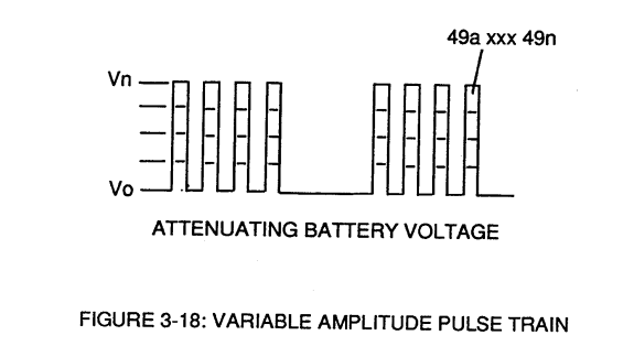
The resultant pulse wave form (49a xxx 49n) of Figure (3-18) superimposed onto primary coil (26) is exact duplicate of proportional pulse train (47a xxx 47n).
How it is written
- (49a xxx 49n) 22×
- (49) 8×
- (49/51) 3× with (51) Opposite Electrical Voltage Fields
- (49a xxx 49n - T3 - 49a xxx 49n) 2× with (T3) Unipolar Pulse-Train
- (49a xx 49n) 2×
- (49a xxx 49n - T3 - 49a xxx 49a) 1× with (T3) Unipolar Pulse-Train
- (49a xxx 1'3 xxx 49n) 1×
- (E11/E12 ... 49a xxx 49n) 1×
49a xxx 49n is Meyer's shorthand for a run of the same thing: 49a is the first, 49n the last, and the x's stand for however many lie between. Every stage of the run is this one numeral. A pair before the letters, 583/602a, is a run of two things that go together, one of each per stage.
Drawings 131
-
Figure (3-22) · Analog Voltage generator (40)
-
Figure (3-22) · Voltage Amplitude Control Circuit (50)
-
Figure (3-18) · Cell Driver Circuit (90)
-
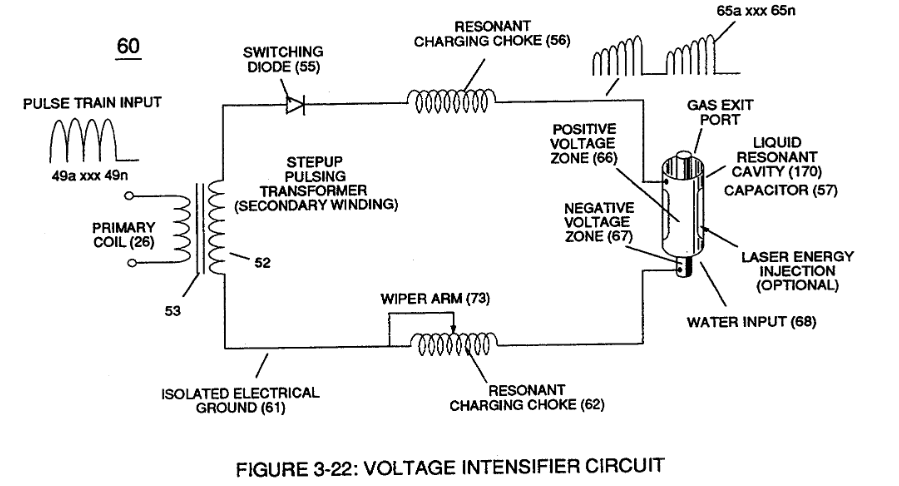
Figure (3-22) · Voltage Intensifier Circuit (60)
-
Figure (3-22) · Voltage Dynamics
-
Voltage Intensifier Circuit (60) of Figure (3-22) · Gas Processor
-
(270) of Figure (3-34) · Gas Processor
-
Carries this number · WFC 422DA - Illustrations
-
Carries this number · WFC 422DA - Illustrations
-
Carries this number · WFC 422DA - Illustrations
-
(70) of Figure (3B) · Water Fuel Injector (Taper Resonant Cavity Chamber)
-
Electronic Circuit (110) of Figure (7) · Water Fuel Injector (Taper Resonant Cavity Chamber)
-
(220) of Figure (18) · Water Fuel Injector (Taper Resonant Cavity Chamber)
-
Carries this number · Water Fuel Injector (Taper Resonant Cavity Chamber)
-
The Following Page 1-7 was not available · Water Fuel Injector (Taper Resonant Cavity Chamber)
-
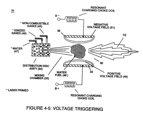
Figure (4-5) · Water Fuel Injection System - Page 1
-
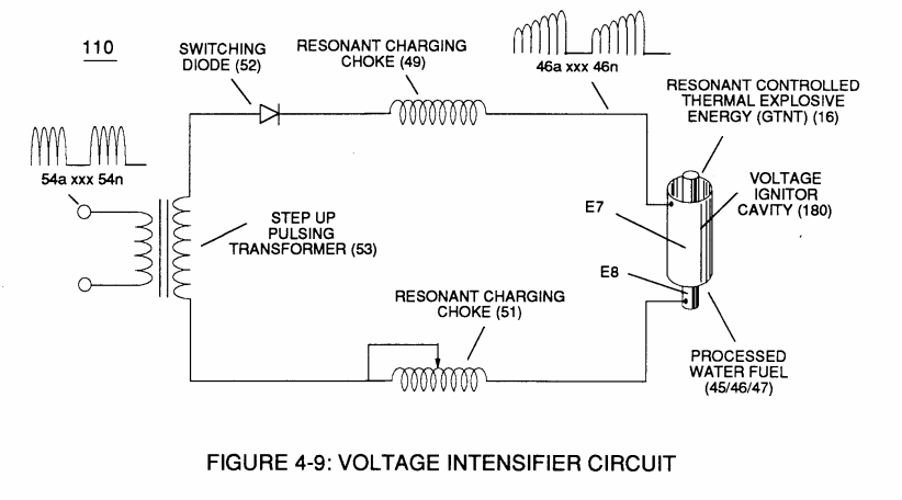
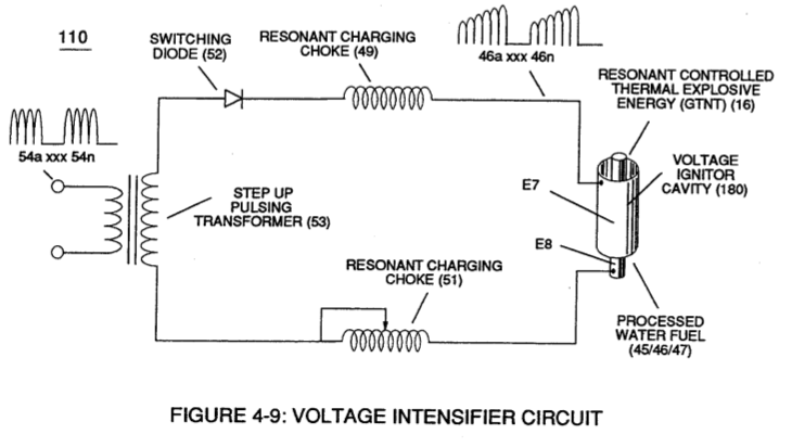
Figure (4-9) · Water Fuel Injection System - Page 2
-
but, also prevents electron flow into destabilizing gas process (180), as so illustrated in Figure (4-5). · Water Fuel Injection System - Page 3
-
Carries this number · In Application of Usage
-
(110) of Figure (4-9) · In Application of Usage
-
(270) of (3-34) · In Application of Usage
-
Voltage Triggering Process (70) of Figure (4-5) · Voltage Intensifier Coil-Assembly
-
Carries this number · VIC Matrix Circuit
-
Voltage Intensifier Circuit (60) of Figure (3-22) · Instant Explosion of Water
-
Voltage Intensifier Circuit (620) of Figure (7-1) · Instant Explosion of Water
-
(56/62) of Figure (3-22) · Instant Explosion of Water
-
(T2) of Figure (7-8) · Instant Explosion of Water
-
(56) of Figure (3-22) · Instant Explosion of Water
-
(620) of Figure (7-1) · Instant Explosion of Water
-
Figure (7-8) · Resistance (Rs)
-
(16) of Figure (4-5) · Resistance (Rs)
-
(110) of Figure (4-9) · Resistance (Rs)
-
(620) of Figure (7-1) · Resistance (Rs)
-
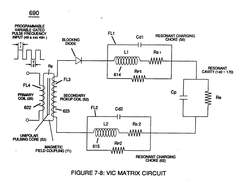
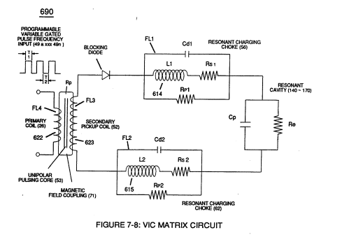
(690) of Figure (7-8) · Resistance (Rs)
-
(614) of Figure (7-1) · Inductance (FL)
-
(690) of Figure (7-8) · Inductance (FL)
-
Inductor (614) of Figure (7-1) · Inductance (FL)
-
(614) of (7-1) · Inductance (FL)
-
Figure (7-1) · Capacitance (Cd)
-
(690) of Figure (7-8) · Capacitance (Cd)
-
(690) of Figure (7-8) · Inductance Reactance (Rs - Cd - FL)
-
"Electron Bounce" phenomenon (700) of Figure (7-9) · Inductance Reactance (Rs - Cd - FL)
-
Figure (7-8) · Inductance Reactance (Rs - Cd - FL)
-
(620) of Figure (7-1) · Inductance Reactance (Rs - Cd - FL)
-
(690) of Figure (7-8) · Taper Resonant Capacitor (ERt)
-
Figure (4-5) · Capacitance Reactance
-
690 of Figure 7-8 · Circuit Resistance
-
Choke-Coil (62) of Figure (7-1) · Transformer Action
-
(52) of Figure (7-8) · Electron Bounce Phenomenon
-
Carries this number · WFC 426 - Illustrations
-
(690) of Figure (7-8) · 8-2 - Traveling Voltage Wave-Guides
-
(631) of Figure (7-9) · 8-3 - Electrical Voltage-Pulse Wave-Transmission
-
(52) of Figure (7-8) · 8-3 - Electrical Voltage-Pulse Wave-Transmission
-
(Cp) of Figure (7-8) · 8-4 - State Space (Sp)
-
Figure (4-5) · 8-5 - Energy Vectoring (Ev)
-
(620) of Figure (7-1) · 8-6 - VIC Voltage Sync-Pulse Circuit
-
(690) of Figure (7-8) · 8-6 - VIC Voltage Sync-Pulse Circuit
-
(840) of Figure (8-10) · 8-6 - VIC Voltage Sync-Pulse Circuit
-
(Cp) of (7-8) · 8-6 - VIC Voltage Sync-Pulse Circuit
-
Carries this number · WFC 427 Illustrations
-
Carries this number · WFC Development Objectives
-
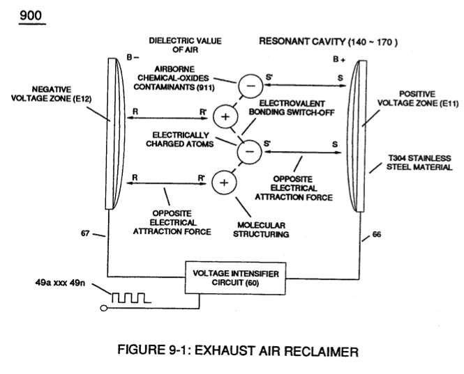
Voltage Intensifier Circuit (110) of Figure (4-9) · WFC Exhaust Air Reclaimer
-
(690) of Figure (7-8) · Propagating Electrical Stress
-
"Resonant Charging Choke" (56) of Figure (7-1) · Propagating Electrical Stress
-
Figure (10-3 A/B) · Propagating Electrical Stress
-
Figure (3-34) · Propagating Electrical Stress
-
Voltage Intensifier Circuit (60) of Figure (3-22) · Propagating Electrical Stress
-
(990) of Figure (10-3) · Propagating Electrical Stress
-
Blocking Diode (52) of Figure (4-9) · Propagating Electrical Stress
-
(60) of Figure (3-22) · Propagating Electrical Stress
-
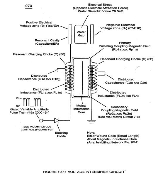
The programmable pulse-frequency (49a xxx 49n) of Figure (10-1) input is simply adjusted to tune-in to the dielectric property of the Water Molecule. · Propagating Electrical Stress
-
Carries this number · Voltage to Amp Differential Ratio
-
blocking diode (55) of Figure (3-34) · Voltage to Amp Differential Ratio
-
Figure (10-3A) · Voltage to Amp Differential Ratio
-
(620) of figure (7-1) · Voltage to Amp Differential Ratio
-
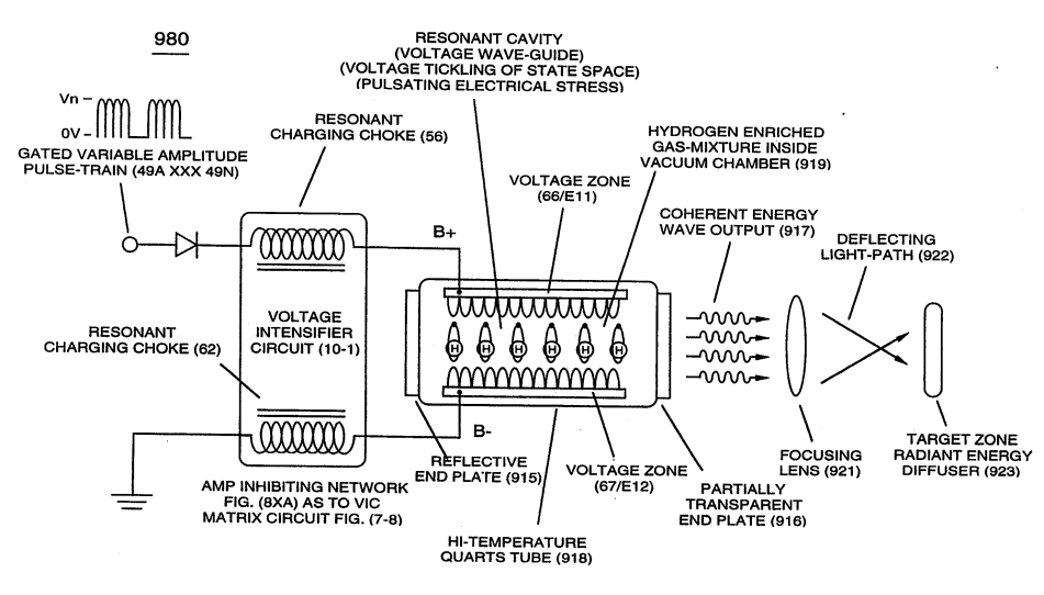
... emitting Coherent Energy Wave-Form (917), as so illustrated in (980) of Figure (10-2). · Optical Thermal Lens
-
Carries this number · WFC 429 - Illustrations
-
Carries this number · WFC 429 - Illustrations
-
Carries this number · WFC 429 - Illustrations
-
Carries this number · WFC 429 - Illustrations
-
Carries this number · WFC 429 - Illustrations
-
Carries this number · Wobbling Effect
-
voltage intensifier circuit (990) of Figure (10-3) · VIC Switchover Circuit
-
(970) of Figure (10-1) · VIC Switchover Circuit
-
Figure (3-28) · Voltage Intensifier Circuit (60)
-
Ohm's law of LC circuit (180) of Figure (3-28) in series is given by (Eq 5) · Voltage Intensifier Circuit (60)
-
Voltage (Vc) of Figure (3-28) across the capacitor is given by (Eq 7) · Voltage Intensifier Circuit (60)
-
The figure it sits on · WFC 422DA - Illustrations
-
The figure it sits on · Electronic Circuit Design
-
The figure it sits on · Differential Air-Gas Inlet Control
-
Figure (5-8) · Energy Pumping Action
-
(550) of Figure (5-8) · In Application of Usage
-
(550) of Figure (5-8) · Covalent Switch-Off
-
(7) of Figure (5-8) · Energy Aperture of the Atom
-
(550) of Figure (5-8) · Solar Energy Actuator
-
"Voltage Intensity of Opposite Potential" (600) of Figure (6-3) · Voltage Intensifier Coil-Assembly
-
The figure it sits on · WFC 425 - Illustrations
-
(628) of Figure (7-7) · Instant Explosion of Water
-
Figure (7-13) · Inductance (FL)
-
(600) of Figure (6-3) · Inductance (FL)
-
(600) of Figure (6-3) · Inductance (FL)
-
(627) of Figure (7-7) · Inductance Reactance (Rs - Cd - FL)
-
(see 740 of Figure 7-13) · Voltage Amplitude Switch-Off
-
The figure it sits on · WFC 426 - Illustrations
-
The figure it sits on · WFC 426 - Illustrations
-
The figure it sits on · 8-1 - Propagating "Resonant Action" By Voltage Tickling of State Space
-
(780A) Figure (8-2) · 8-2 - Traveling Voltage Wave-Guides
-
(770) of Figure(8-1) · 8-2 - Traveling Voltage Wave-Guides
-
Figure (8-2) · 8-2 - Traveling Voltage Wave-Guides
-
(770) of Figure (8-1) · 8-3 - Electrical Voltage-Pulse Wave-Transmission
-
(770 A) of Figure (8-1) · 8-4 - State Space (Sp)
-
(770 B) of Figure (8-1) · 8-4 - State Space (Sp)
-
(780 B) of Figure (8-2) · 8-4 - State Space (Sp)
-
(780 A/B/C) of Figure (8-2) · 8-4 - State Space (Sp)
-
(585) of Figure (8-1) · 8-4 - State Space (Sp)
-
(550 of Figure 5-8) · 8-4 - State Space (Sp)
-
(770A) of Figure (8-1) · 8-5 - Energy Vectoring (Ev)
-
Clipped Voltage Wave-form (780C) of Figure (8-2) · 8-5 - Energy Vectoring (Ev)
-
(612) of Figure (8-1) · 8-5 - Energy Vectoring (Ev)
-
The figure it sits on · 8-6 - VIC Voltage Sync-Pulse Circuit
-
The figure it sits on · WFC 427 Illustrations
-
The figure it sits on · WFC 427 Illustrations
-
The figure it sits on · WFC 427 Illustrations
-
"Electrovalent Switch-off" phenomenon (550) of Figure (5-8) · WFC Exhaust Air Reclaimer
-
"Voltage Tickling of State Space" (770A) of Figure (8-1) · WFC Exhaust Air Reclaimer
-
"Voltage Tickling of State Space" (770B) of Figure (8-1) · WFC Exhaust Air Reclaimer
-
Dynamic Electrical Charging Effect (612) of Figure (8-1) · Propagating Electrical Stress
-
hydrogen energy aperture (7) of (550) of Figure (5-8) · Optical Thermal Lens
-
The figure it sits on · Quartz Tube Configuration & Operational Parameters
-
... establishing variable Dynamic Electrical Charging Effect (612). · Quartz Tube Configuration & Operational Parameters
-
The figure it sits on · Degaussing Radioactive Material
Where it is named · 47
Cell Driver Circuit (90) 2×
-
pulse wave form (49a xxx 49n)
The resultant pulse wave form (49a xxx 49n) of Figure (3-18) superimposed onto primary coil (26) is exact duplicate of proportional pulse train (47a xxx 47n).
-
However, each pulse train (47) (49) are electrically isolated from each other.
Voltage Intensifier Circuit (60) 3×
-
variable controlled switch-gate (49a xxx 49n)
By integrating and joining together variable voltage amplitude control signal (318 xxx 32n) of Figure (3-15) with variable controlled switch-gate (49a xxx 49n) of Figure (3-18) across primary coil (26) of Figure (3-22),
-
applied voltage (49)
The voltage across inductor (56) or capacitor (57) is greater than applied voltage (49) of Figure (3-18).
-
applied voltage (49)
At frequency close to resonance, the voltage across the individual components is higher than applied voltage (49), and, at resonant frequency, the voltage (Vt) of Figure (3-28) across both inductor and the capacitor are theoretically infinite.
Water Fuel Injection System 1×
-
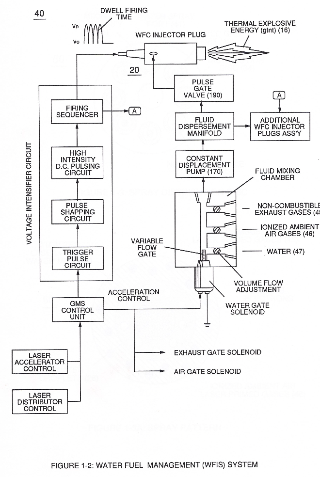
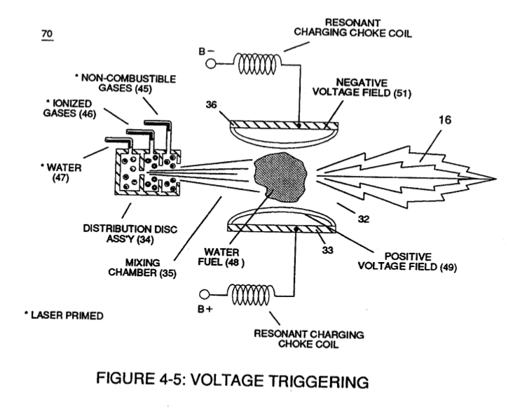
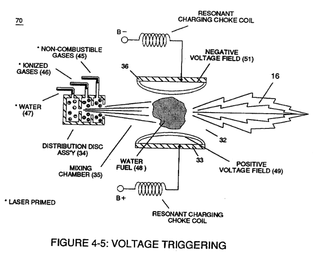
… ic Resonant (240) of Figure (30); but, also sets up and triggers Hydrogen Fracturing Process (390) of Figure (41) as to Figure (6) under control state (on demand) via electrical-static spark ignition (49 / 51) of Figure (3B)....releasing thermal explosive energy (gtnt) (16) passing beyond gas exit port (32) of Figure (3B), as further illustrated in Figure (2) as to Figure (1).
Water Fuel Injector (Taper Resonant Cavity Chamber) 2×
-
opposite electrical voltage fields (49/51)
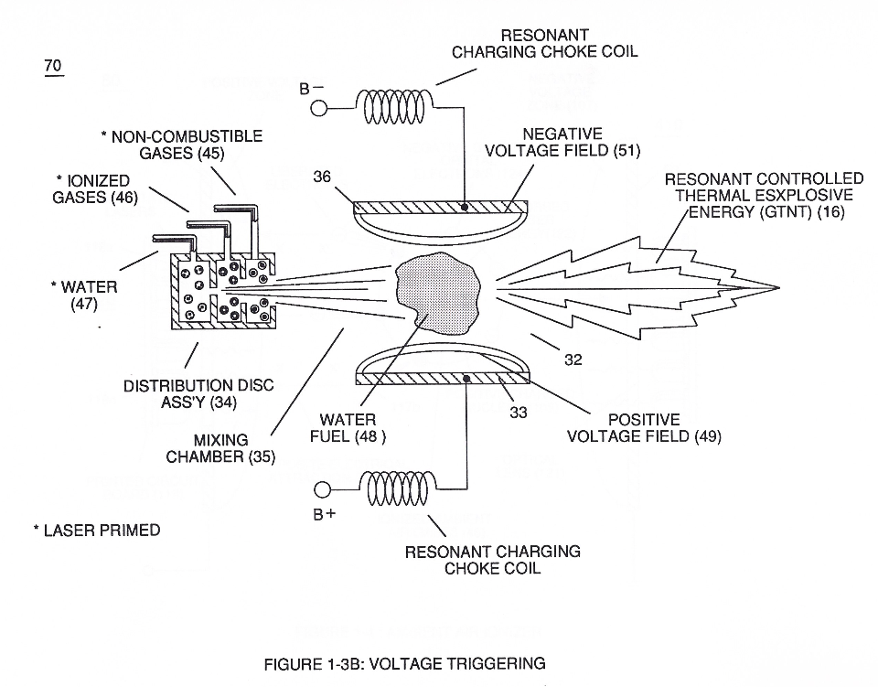
… Resonant Cavity Chamber (180) of Figure (14) to enhance operational parameters of Hydrogen Fracturing Process (100) of Figure (6) being stimulated to activation by opposite electrical voltage fields (49/51) of Figure (3B) as to (180) of Figure (14).
-
Once water fuel-droplets (xxx 48n) fully occupies open space cavity (Resonant Cavity Zone) (35) and then exposed to applied pulsating opposite electrical voltage fields (49/51) of voltage wave form (280) of Figure (17), the electrically stimulated water fuel droplets (48a xxx 48n) are subjected to release thermal explosive energy (gtnt) (16) undergoing Electrical-Resonant in a sequential manner:
Amp Inhibiting Circuit Vs Voltage Enhancement 1×
-
Pulse-Voltage Frequency (49a xxx 49n)
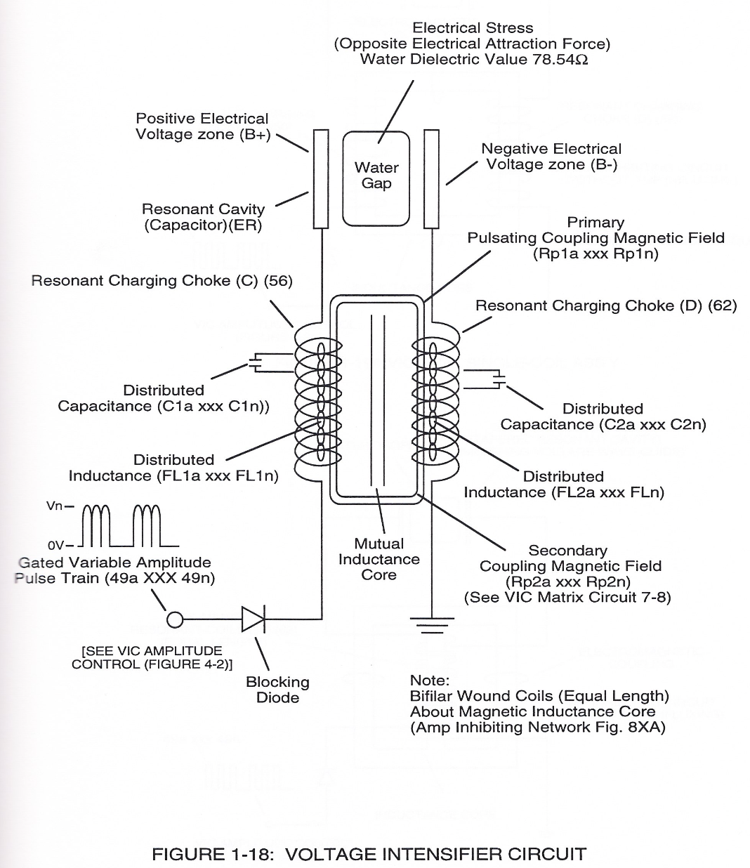
… ounding effect (increasing magnetic field-strength during each pulsing cycle) of electromagnetic field-strength (Rpla xxx Rpin = Rp2a xxx Rp2n) (mutual induction) when applied Pulse-Voltage Frequency (49a xxx 49n) passes through the positive energized Resonant Charging Choke (56).
Water Fuel Injection System - Page 1 1×
-
electrical-static spark ignition (49/51)
but, also, sets up and triggers Hydrogen Fracturing Process (390) of Figure (3-42) as to Figure (3-6) under control state (on demand) via electrical-static spark ignition (49/51) of Figure (4-5)
Instant Explosion of Water 2×
-
Programmable Pulsing Operations (49a xxx 49n)
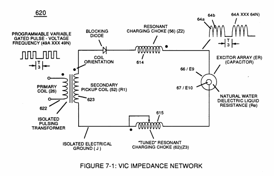
Voltage Intensifier Circuit (60) of Figure (3-22) (Memo WFC 422 DA) as to Figure (1-1) (Memo WFC 420) and Voltage Intensifier Circuit (620) of Figure (7-1) are specifically designed to restrict amp flow during Programmable Pulsing Operations (49a xxx 49n) but in different operational modes:
-
... input-signal (49a xxx 49n) being a Pulse-Train where (T2) pulse offtime (T2) is adjusted to allow Unipolar Pulse-Train (64a xxx T3 xxx 64n)
Resistance (Rs) 1×
-
Voltage Pulsing Operation (49a xxx 49n)
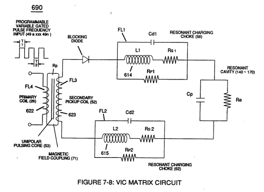
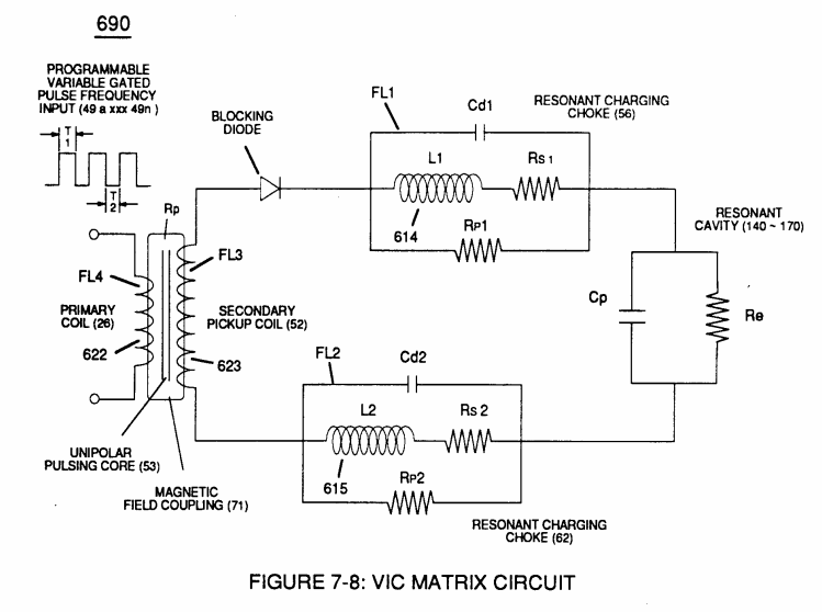
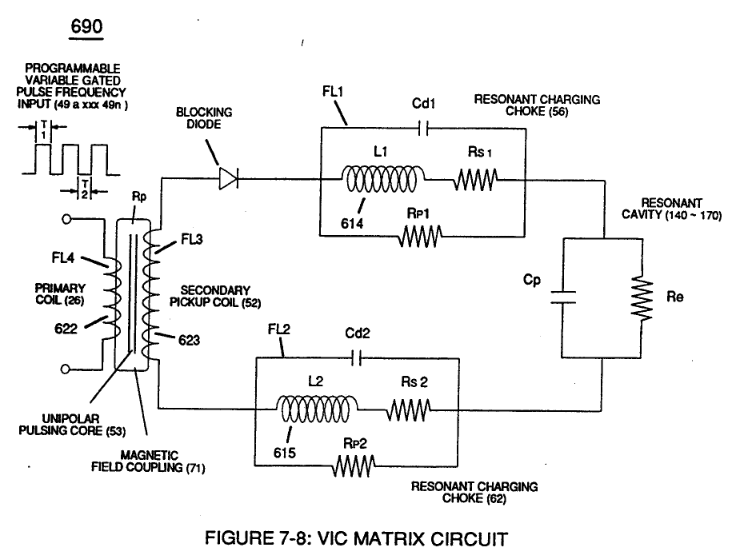
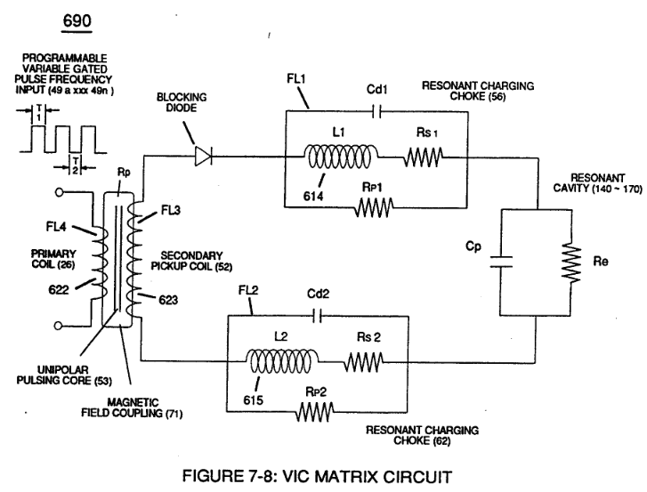
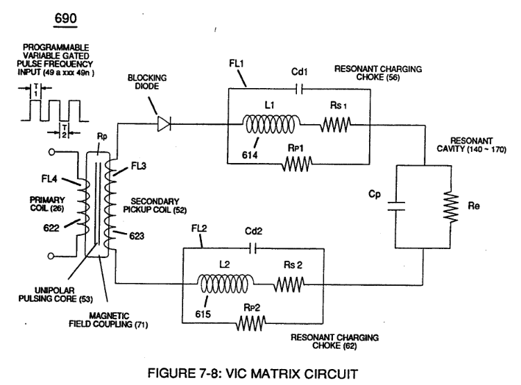
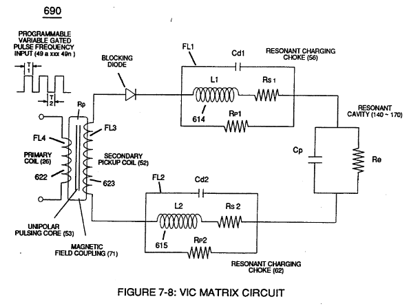
... allowing the dielectric value of Water (Re) to be a part of Voltage Intensifier Circuit (110) of Figure (4-9) capability of restricting amp flow during Voltage Pulsing Operation (49a xxx 49n) of (620) of Figure (7-1) as to VIC Matrix Circuit (690) of Figure (7-8)
Inductance (FL) 1×
-
Voltage Pulse frequency (49a xxx 49n)
Component Interaction promotes Component Reactance during D.C. pulsing operations while allowing variable voltage amplitude (Vo - Va -Vb - Vn) of Figure (7-13) to be attenuated independently of Voltage Pulse frequency (49a xxx 49n), as so illustrated in (600) of Figure (6-3).
Inductance Reactance (Rs - Cd - FL) 2×
-
D.C. Pulsing (49a xxx 49n)
Inductance Reactance occurs when resistance (Rs), capacitance (Cd), and Inductance (FL) interacts together during D.C. Pulsing (49a xxx 49n), as schematically depicted in (690) of Figure (7-8).
-
Pulse-Frequency (49a xx 49n)
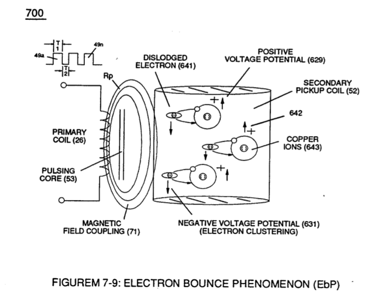
… in equal electromagnetic intensity (FL1 = FL2) to encourage and promote "Electron Bounce" phenomenon (700) of Figure (7-9) while adjusting (programmable pulse wave-form) input signal Pulse-Frequency (49a xx 49n) to "tune-in" to the "dielectric property" (Re) of water (85) causing amp flow to be reduce to a minimum value while allowing voltage potential (627) of Figure (7-7) to go toward infinity if the elect …
In-Line Circuit Components 3×
-
Gated Pulse-Frequency (49a xxx 49n - T3 - 49a xxx 49n)
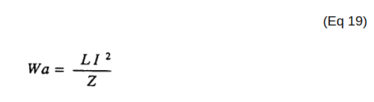
Inductance Reactance directly determines "Stored" Energy (Wa) which is controlled by input Voltage Potential attenuated or varied by way of Voltage Amplitude (Vo xxx Va xxx V b - Vf xxx Vg xxx Vn) of Figure (7-13) and/or Gated Pulse-Frequency (49a xxx 49n - T3 - 49a xxx 49n), or both.
-
... determining voltage swing from highest voltage level (Vn) to volts switch-off point (Vff), and establishing Impedance (FL) which minimizes heat loss of electrical input power (49) by impairing electron movement.
-
Voltage Potential (49a xxxx 49n - T3 - 49a xxx 49n)
Gated Pulse-Frequency of applied Voltage Potential (49a xxxx 49n - T3 - 49a xxx 49n)
Transformer Action 3×
-
Voltage (49)
Inductance Core (53) of Figure (6-1) composed of "Grain Oriented" Electrical Steel laminations step up applied Voltage (49) when Magnetic Field Coupling (71) of Figure (7-8) cross over to Secondary Pickup Coil-winding (52) which has more turns of wire than Primary Coil- winding (26) by way of "Eddy" currents that induce m …
-
(Ip) is the amount of current flow in the Primary Coil-Winding (26) when electrically "energized" during pulsing operations (49a xxx 49n - T3 - 49a xxx 49a).
-
… one side of Water Gap (Cp) of Figure (7-8) is accomplished by low electrical power input (Tab 38) when Choke-Coil (62) of Figure (7-1) magnetic field (FL2) (690) of Figure (7-8) during pulse on-time (49) impede "Electron-Flow" since electron mass is composed of electromagnetic matter which interacts with magnetic field strength (FL2).
Electron Bounce Phenomenon 2×
-
… closed-loop magnetic pulsing core (53) of Figure (190) penetrates Inductance coil-windings (52 - 56 - 62) simultaneously during each and every pulse on-time (T1a xxx T1n) as programmable pulse-train (49a xxx 49n T3 - 49a xxx 49n) is adjusted to "Tune - in" to the dielectric property of Water (Re)
-
... producing Dynamic Voltage Potential (600) of Figure (6-3) during repetitive pulsing (49a xxx 49n - T3 - 49a xxx 49n)
Voltage Amplitude Switch-Off 1×
-
Pulse-train (49a xx 49n - T3 - 49a xxx 49n)
Switching the member of Secondary Coil-Array (505a xxx 505n) maximizes electrical power transfer from Primary Coil (26) to Secondary Coil (52) by keeping Voltage Amplitude of Pulse-train (49a xx 49n - T3 - 49a xxx 49n) constant.
8-2 - Traveling Voltage Wave-Guides 2×
-
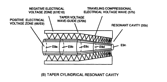
… Circuit (690) of Figure (7-8) (WFC memo 426) as to VIC Coil Assembly (580) of Figure (6-1) (WFC memo 425) ability to inhibit amp "influxing" (Electron Bounce Phenomenon EbP) during pulsing operations (49a xx 49n) allows voltage amplitude of pulse-frequency potential (T1a xxxT1n) as to (Vo -64a-64b -64c - Vn) of (780A) Figure (8-2) to be applied across cross-sectional circular-ring water bath (85) (donut shape …
-
Voltage Intensifier Matrix Circuit (690) of Figure (7-8) electrically connected with resistive liquid (85/Re) (forming Resonant Water Gap "Cp" of Figure 7-8) propagates the transmission of Traveling Voltage Wave-Form (57) of Figure (6-2) as to (770) of Figure(8-1) by the functional relationship of Circuit Resistance Equation (Eq 9) during programmable Voltage Pulsing operations (49a xxx 1'3 xxx 49n) of Figure (8-2).
8-3 - Electrical Voltage-Pulse Wave-Transmission 3×
-
Voltage Pulse Frequency (49a xxx - 1'3 - xxx 49n)
Electrical Voltage-Pulse Wave-Transmission (583a xxx 583n), now formed, occurs along Electrical Conductance Zone (587) since applied Electrical Pulse Voltage amplitude (Vo - 64a - 64b- 64c - Vn) is time responsive (T1/T2a - T3 – T1/T2n) to incoming gated Voltage Pulse Frequency (49a xxx - 1'3 - xxx 49n).
-
Voltage Pulse Frequency (49a xxx 49n)
Each Voltage Pulse duration time-period (T1 on time) from start to finish is directly related to applied Voltage-Pulse Amplitude (Vo xxx Vn) and reoccurring Voltage Pulse Frequency (49a xxx 49n) forming "Unipolar Voltage Pulse-Wave" (583) from zero voltage ground state (Vo) to a predetermined Voltage Level ( xxx 64 x - 64y - 64z - Vn) on the leading edge of the Voltage Pulse-Wave (Vpa) and, …
-
incoming signal (49a xxx 49n)
The newly established leading voltage edge (Vpa) and trailing voltage edge (Vpb) being uniform in shape/configuration since both Resonant Charging Chokes (56/Z2 – 62/Z3) resistive values are the same (Typically 11.6 kΩ each) and incoming signal (49a xxx 49n) is electrically linked with Water-Gap Capacitor (Cp) of Figure (7-8) having dielectric liquid of Water (85) there between.
8-4 - State Space (Sp) 1×
-
Voltage Burst-Frequency (49a xxx 49n)
The newly formed Opposite Electrical Attraction Force (RR' - SS') intensity is directly related to the applied Voltage Amplitude Burst-Time (Vpa - Vn -Vpb) as to the Voltage Burst-Frequency (49a xxx 49n) as to Voltage Peak Excursion Point "P" at the height of Unipolar Voltage Pulse Wave (583/602) which, in turns, determines maximum Voltage Peak-Potential (Vpp) at any given time during each Voltage Pu …
8-5 - Energy Vectoring (Ev) 3×
-
Voltage Pulse Operation (49a xxx 49n)
… which combined together (Vpf + Vpb) Electrical Stress (Es) variances corresponds to the Voltage Pulse Shape of each synchronized opposite Voltage Pulse Wave (583 - 602) of (770A) of Figure (8-1) being produced during applied Voltage Pulse Operation (49a xxx 49n);
-
… Electrical Charging Effect (585) is being held constant since Electrical Stress Force (Est) averages out either Dynamic State Space (Dss) or Static State Space (Sss) during repeated pulsing operation (49a xxx 49n).
-
... producing Dynamic Electrical Charging Effect (612) of Figure (8-1) that increases Electrical Stress Pressure (Espa + Espb + Espc, and so on) continually during each gated voltage pulsing cycle (49a xxx T3 xxx 49n).
8-6 - VIC Voltage Sync-Pulse Circuit 2×
-
Pulsing Operations (49a xxx 49n)
Blocking Diode (618) functions as an "Electrical Isolator" that prevents electrical discharge of Dual Secondary Coil (616A / B) during applied Pulsing Operations (49a xxx 49n).
-
To ensure and maintain Capacitance Charging Effect (650) of Figure (7-4) across Water-Gap (Cp) of (7-8) during applied pulsing operations (49a xxx 49n), Crossover Voltage Wave-Form (780B) as to (780C) of Figure (8-2) is generally utilized by not allowing Convergent Point "Q" of Figure (780B) to reach Electrical Ground Point (0V) when each Unipolar V …
WFC Exhaust Air Reclaimer 2×
-
This is accomplished since the Voltage Intensifier Circuit (110) of Figure (4-9) is pulsed sensitive (49a xxx 49n) to tune-in to the dielectric properties of the airborne gas-molecule to not only activate Covalent Switch-Off phenomenon (550) of Figure (5-8) by restricting amp influxing to cause "Electrical Stress …
-
pulse-stimulation (E11/E12 ... 49a xxx 49n)
Air purification by atomic deflection (900) of Figure (9-1) is possible since airborne atoms are neither destroyed nor created during exposure to "Voltage" pulse-stimulation (E11/E12 ... 49a xxx 49n) propagating "Electrical Stress" pulse-waves (Mm'- ASS') which, in turn, induces "Electrovalent Switch-off" phenomenon (550) of Figure (5-8).
Propagating Electrical Stress 4×
-
The energized "Resonant Charging Choke" (56) of Figure (7-1) as to Figure (10-1) by way of input voltage-pulses (49a xxx 49n) creates an electromagnetic coupling field (Rp1) of Figure (7-8) due to its self-inductance (640) of Figure 7-3B) crosses over and passes through electrically ground connected Resonant Charging Choke (62), as so illustrated in Figure (10-1)
-
Voltage Pulse-Potential (Va xxx Vn/49a xxx 49n)
… The length and diameter size of the copper-wire spiral wrapped coil (56/62) of Figure (10-1) being paired together and electrically energized in conjunction with applied Voltage Pulse-Frequency determines how much "Amp Leakage" will occur across capacitor Gap (Cp) while "Voltage Pulse-Potential" (Va xxx Vn/49a xxx 49n) of "Opposite polarity" (B+/B-) is/are allowed to be applied across "Electrical Voltage Plates" (Voltage-Zones) (66/67).
-
… ounding effect (increasing magnetic field-strength during each pulsing cycle) of electromagnetic field-strength (Rp1a xxx Rp1n - Rp2a xxx Rp2n) (mutual induction) when applied Pulse-Voltage frequency (49a xxx 49n) of Figure (3-34) passes through the positive energized Resonant Charging Choke (56).
-
The programmable pulse-frequency (49a xxx 49n) of Figure (10-1) input is simply adjusted to tune-in to the dielectric property of the Water Molecule.
Voltage to Amp Differential Ratio 1×
-
Pulse-Train Waveform (49a xxx 49n)
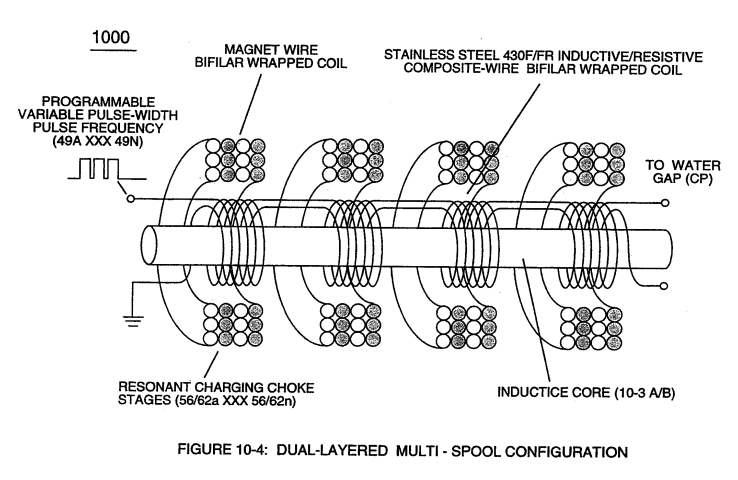
Opposite polarity Voltage Wave burst (1010) of Figure (10-5) as to Dynamic Voltage Stimulation (770B) of Figure (8-1) is simply produced when Programmable Variable Pulse-Width Pulse-Train Waveform (49a xxx 49n) is allowed to be electrically transmitted through and beyond Resonant Charging Chokes Stages (56/62a xx 56/62n + SS56/62a xxx SS56/62n) of Figure (10-4) that are not only electrically connected in se …
Optical Thermal Lens 1×
-
The Energy Pumping Stage (520) of Figure (5-3) as to (500) of Figure (5-1) attenuates the hydrogen energy aperture (7) of (550) of Figure (5-8) when applied Opposite Voltage Potential (Va xxx Vn) (49a xxx 49n) (B+/B-) produces pulsating Electrical Stress Wave-form (opposite electrical attraction force) (RU/RU' - ST/ST'a xxx RU/RU' ST/ST'n) during Pulsing Operations.
A Technique Called "Easer" 2×
-
Input Pulse Frequency (49)
… 5) that have ~to a higher energy state (activated state) (K to L orbit or beyond) suddenly jumps back to its original lower energy state (quiescent state) (back to K orbit) when Input Pulse Frequency (49) terminates Voltage-Sync Pulse (Vsp) during applied pulse off-time (T2) of Figure (7-8)
-
Voltage Pulse Cycling (49a xxx 49n)
Together but in separate variable forms, Applied Voltage Peak Potential (Vpp),Voltage Pulse Cycling (49a xxx 49n), and Opposite Voltage Potential (Vgpa xxx Vgp) forming Voltage Sync-Pulse (49-Vpp-Vgpa xxx 49-Vpp-Vgpn) determines the energy-intensity (Eie) of the coherent-beam (919).
Appendix B - Glossary of Applicaiton Notes 1×
-
… one side of Water Gap (Cp) of Figure (7-8) is accomplished by low electrical power input (Tab 38) when Choke-Coil (62) of Figure (7-1) magnetic field (FL2) (690) of Figure (7-8) during pulse on-time (49) impede "Electron-Flow" since electron mass is composed of electromagnetic matter which interacts with magnetic field strength (FL2). …