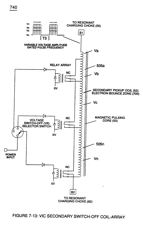
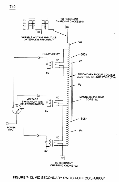
Figure (7-13)
VIC Secondary Switch-off Coil-array
How it is written
- (7-13) 5×
- (see 740 of Figure 7-13) 2× with (740)
Drawings 4
-
Figure (7-13) · Inductance (FL)
-
(see 740 of Figure 7-13) · Voltage Amplitude Switch-Off
-
Captioned as this figure · WFC 426 - Illustrations
-
Beside the passage · In-Line Circuit Components
On this figure 10
- 49 Voltage Pulse frequency
- 505 Secondary Coil-cavities
- 740 —
- T3 Unipolar Pulse-Train
- V Voltage Amplitude
- Va —
- Vb VIC Voltage Enhancement Circuit
- Vn Voltage Potential
- Vo Applied Voltage Amplitude
- Wa Energy
Where it is named · 7
Inductance (FL) 2×
-
Component Interaction promotes Component Reactance during D.C. pulsing operations while allowing variable voltage amplitude (Vo - Va -Vb - Vn) of Figure (7-13) to be attenuated independently of Voltage Pulse frequency (49a xxx 49n), as so illustrated in (600) of Figure (6-3).
-
Figure (7-13)
In-Line Circuit Components 1×
-
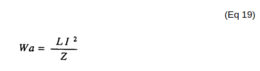
Inductance Reactance directly determines "Stored" Energy (Wa) which is controlled by input Voltage Potential attenuated or varied by way of Voltage Amplitude (Vo xxx Va xxx V b - Vf xxx Vg xxx Vn) of Figure (7-13) and/or Gated Pulse-Frequency (49a xxx 49n - T3 - 49a xxx 49n), or both.
Voltage Amplitude Switch-Off 4×
-
Voltage levels of variance (Va xxx Vn) is achieved by simply switching-in or switching-out the member of Secondary Coil-cavities (505a xx 505n) (see 740 of Figure 7-13) in direct relationship to Taper Resonant Voltage surfaces (E9/10) of Figure (6-2) which acts and performs as a "Voltage Amplifier" when Compressional Wave-form (B) of Figure (7-12) is intensified at Exit Port (32) of Figure (6-2).
-
Voltage levels of variance (Va xxx Vn) is achieved by simply switching-in or switching-out the member of Secondary Coil-cavities (505a xx 505n) (see 740 of Figure 7-13) in direct relationship to Taper Resonant Voltage surfaces (E9/10) of Figure (6-2) which acts and performs as a "Voltage Amplifier" when Compressional Wave-form (B) of Figure (7-12) is intensified at Exit Port (32) of Figure (6-2).
-
(see 740 of Figure 7-13)