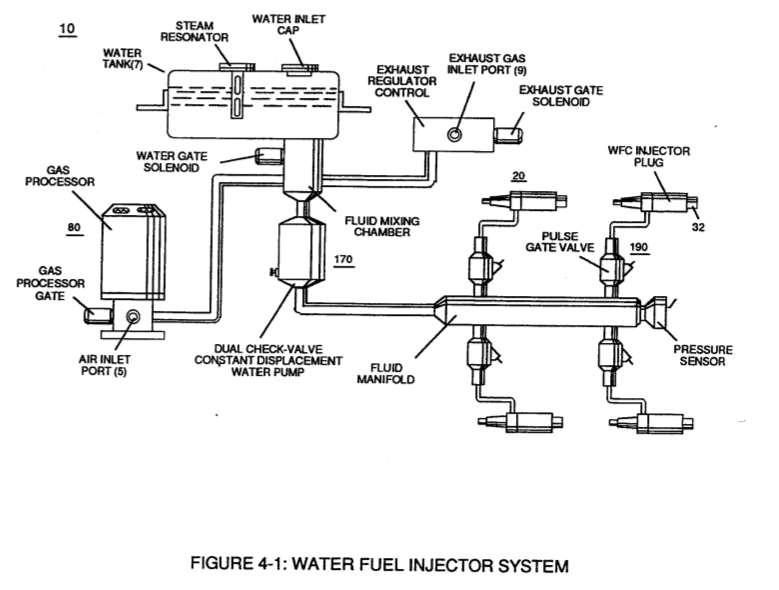
Figure (4-1)
Water Fuel Injector System
How it is written
- (4-1) 21×
Drawings 4
-
reciprocating WFC Fuel-kits can be similar to Car design (340); · Aviation Application
-
Captioned as this figure · Electronic Circuit Design
-
Figure (4-1) · Water Fuel Injection System - Page 1
-
"FullSystem" development (10) of Figure (4-1) · WFC Development Objectives
On this figure 6
- 2O Cluster Array
- 10 Led Pickup Circuit
- 16 Flame Projection
- 20 Laser Accelerator Assembly
- 30 Circuit
- 190 Voltage Intensifier Circuit
Where it is named · 21
Aviation Application 2×
-
whereas, Water Fuel Injector kits (10) of figure (4-1) can alternately be used as a self-contained Fuel-unit having no pre-pressurized vessel which converts water directly in thermal explosive energy (gtnt) on demand, as illustrated in WFC memo 423 DA.
-
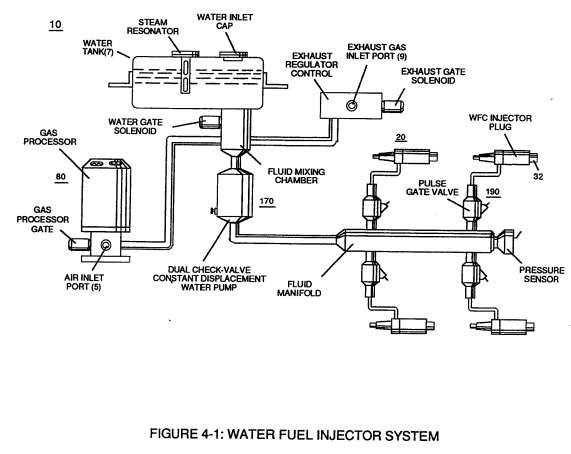
In terms of mechanical interfacing: Water Fuel Injector Assembly (10) of Figure (4-1) can replace standard fuel-injector ports of existing jet engines as shown in (150) of Figure (4-13); or be utilized in Furnace Nozzle Assembly (140) of Figure (4-12) for grain dryers or conventional\heating systems;
Operational Parameters 2×
-
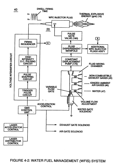
Coupling and subsequently integrating Hydrogen Gas Management (GMS) system (440) with either Hydrogen Fuel-Gas Assembly (450) of Figure (3-1) or Water Fuel Injector Assembly (10) of Figure (4-1) as to Water Fuel Management (WFMS) System (40) of Figure (4-2), now, sets up a full engineering system-approach on how to use Water as a "New" fuel-source.
-
Water Fuel Injector Assembly (10) of Figure (4-1)
Water Fuel Injection System - Page 1 7×
-
Figure (4-1)
-
Secondly, ionized air gases (46a xxx 46n) of Figure (4-4) (laser primed ambient air gases having missing electrons) produced by Ambient Air Ionizer (80) of Figure (4-6) as to Figure (4-1) and non-combustible gases (45) of Figure (4-4) are intermixed with expelling water mist (47a xxx 47n) to form Water-fuel mixture (48) by way of gas mixing disc (34) of Figure (4-5) as to (30) of Figure (4-2);
-
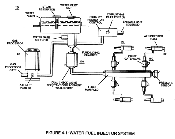
Figure (4-1)
Water Fuel Injection System - Page 3 4×
-
Incoming ambient air gases (5a xxx 5n) become laser primed and ionized when passing through Ambient Air Ionizer (Gas Processor) (80) of Figure (4-6) as to (10) of Figure (4-1) since electron extraction circuit (120) of Figure (4-10) not only captures and consumes ejected electrons (7a xx 7n) of Figure (4-8);
-
(10) of Figure (4-1)
-
Additional WFC Injector Assemblies (20) of Figure (4-1) are arranged in cluster array (20a xxx 2On) to increase energy-yield output (16a xxx 16n) of Figure (4-12/4-13/4-14).
-
WFC Injector Assemblies (20) of Figure (4-1)
Water Fuel Injection System - Page 4 4×
-
... especially when ionized ambient air gases (400 xxx 46n) and non-combustible gases (45a xxx 45n) are intermixed with water supply (47) prior to entering Water Fuel Injector Plug (20/30), as illustrated in (40) of Figure (4-2) as to (10) of Figure (4-1).
WFC Development Objectives 2×
-
The primary Purpose/objective of Water Fuel Injection System (590) of Figure (6-2) as to "FullSystem" development (10) of Figure (4-1) is, in the realm of scientific quest, to help reverse the damage being done to "Earth Ecological Life Support System" by first of all encouraging the use of "Water" as a new "Fuel" source
-
"FullSystem" development (10) of Figure (4-1)