(505) · also written as a run, 505a xxx 505n
Secondary Coil-cavities
Also written Secondary Coil-Array · Secondary Coil-Wrap
Where it is first named
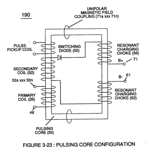
Secondary pickup coil (52) of Figure (3-23) is, also, composed of individual spiral wrapped coils (505a xxx 505n) (typically .002 Ga. magnet wire) electrically connected in sequential order to form bobbin cavity (506) which is placed on top of and in space relationship to primary coil cavity (504).
How it is written
- (505) 4×
- (505a xxx 505n) 3×
- (505a xx 505n) 1×
505a xxx 505n is Meyer's shorthand for a run of the same thing: 505a is the first, 505n the last, and the x's stand for however many lie between. Every stage of the run is this one numeral.
Drawings 20
-
Carries this number · Electronic Circuit Design
-
coil-structures (580) of Figure (6-1) · Voltage Intensifier Coil-Assembly
-
Figure (7-13) · Inductance (FL)
-
(580) of Figure (6-1) · Inductance (FL)
-
(710) of Figure (7-10) · Inductance (FL)
-
(710) of Figure (7-10) · Capacitance (Cd)
-
(580) of Figure (6-1) · Multi-layer Coil
-
(710) of Figure (7-10) · Transformer Action
-
(see 740 of Figure 7-13) · Voltage Amplitude Switch-Off
-
Carries this number · WFC 426 - Illustrations
-
Carries this number · WFC 426 - Illustrations
-
(580) of Figure (6-1) · Voltage to Amp Differential Ratio
-
Figure (3-23) · Voltage Intensifier Circuit (60)
-
Figure (3-23) · Voltage Dynamics
-
The figure it sits on · WFC 422DA - Illustrations
-
(190) of Figure (3-23) · Tri - Coil Construction
-
Inductance Pulsing-Core (190) of Figure (3-23) · Inductance Reactance (Rs - Cd - FL)
-
... each bobbin cavity adhering to equation (Eq 20), as illustrated in (710) of Figure (7-10). · Transformer Action
-
The figure it sits on · Electron Bounce Phenomenon
-
(580) of Figure (6-1) (WFC memo 425) · 8-2 - Traveling Voltage Wave-Guides
Where it is named · 8
Tri - Coil Construction 1×
-
Secondary pickup coil (52) of Figure (3-23) is, also, composed of individual spiral wrapped coils (505a xxx 505n) (typically .002 Ga. magnet wire) electrically connected in sequential order to form bobbin cavity (506) which is placed on top of and in space relationship to primary coil cavity (504).
Transformer Action 5×
-
Secondary Coil-Wrap (505)
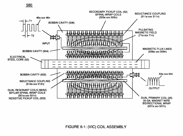
(Ns) is the number of turns of wire that make up Secondary Coil-Wrap (505) of Figure (6-1),
-
(Ns) is the number of turns of wire for each bobbin cavity (505) of Figure (6-1) as to (710) of Figure (7-10) that are electrically connected in series arrangement (505a xxx 505n) to form Secondary Coil-Wrap (52),
-
(Ns) is the number of turns of wire for each bobbin cavity (505) of Figure (6-1) as to (710) of Figure (7-10) that are electrically connected in series arrangement (505a xxx 505n) to form Secondary Coil-Wrap (52),
-
(505) of Figure (6-1)
-
(505) of Figure (6-1)
Voltage Amplitude Switch-Off 2×
-
Secondary Coil-cavities (505a xx 505n)
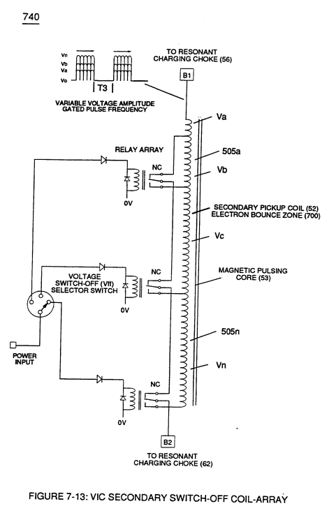
Voltage levels of variance (Va xxx Vn) is achieved by simply switching-in or switching-out the member of Secondary Coil-cavities (505a xx 505n) (see 740 of Figure 7-13) in direct relationship to Taper Resonant Voltage surfaces (E9/10) of Figure (6-2) which acts and performs as a "Voltage Amplifier" when Compressional Wave-form (B) of Figure (7-12) is intensified at Exit Port (32) of Figure (6-2).
-
Secondary Coil-Array (505a xxx 505n)
Switching the member of Secondary Coil-Array (505a xxx 505n) maximizes electrical power transfer from Primary Coil (26) to Secondary Coil (52) by keeping Voltage Amplitude of Pulse-train (49a xx 49n - T3 - 49a xxx 49n) constant.