(ER)
Excitor-Array
Also written capacitor · Voltage Zones · Dielectric Capacitor Gap · Capacitance
Where it is first named
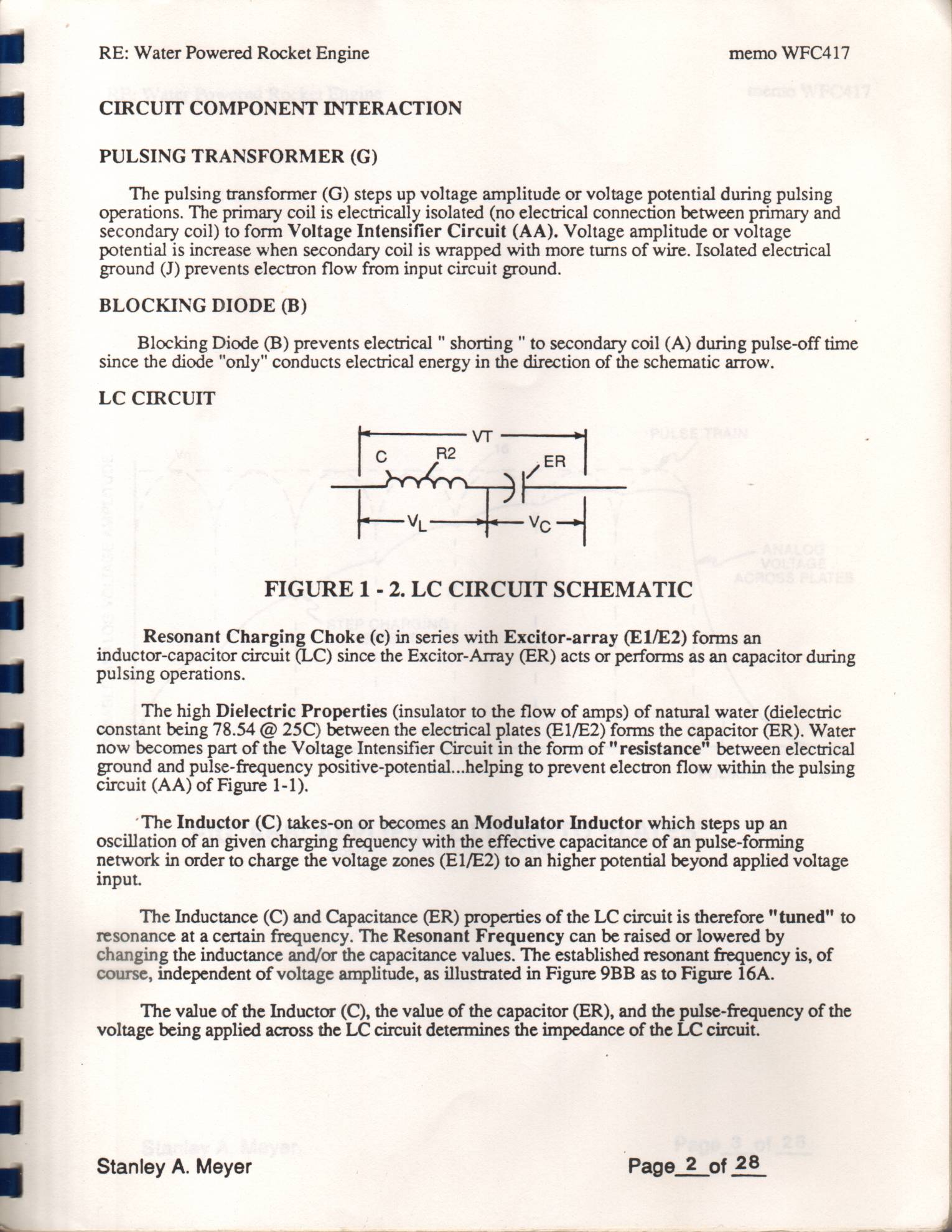
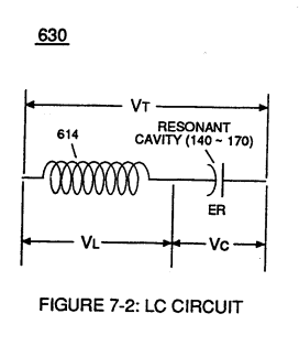
Resonant Charging Choke (c) in series with Excitor-array (E1/E2) forms an inductor-capacitor circuit (LC) since the Excitor-Array (ER) acts or performs as an capacitor during pulsing operations.
How it is written
- (ER) 26×
Drawings 93
-
Stanley A. Meyer Page_2 of 28 · WFC 417 — WFC 417
-
Stanley A. Meyer Page_5 of 28. · WFC 417 — WFC 417
-
Stanley A. Meyer Page_6 of 28 · WFC 417 — WFC 417
-
Stanley A. Meyer Page 12 of 28 · WFC 417 — WFC 417
-
Operational Parameters · RE: Electrical Particle Generator
-
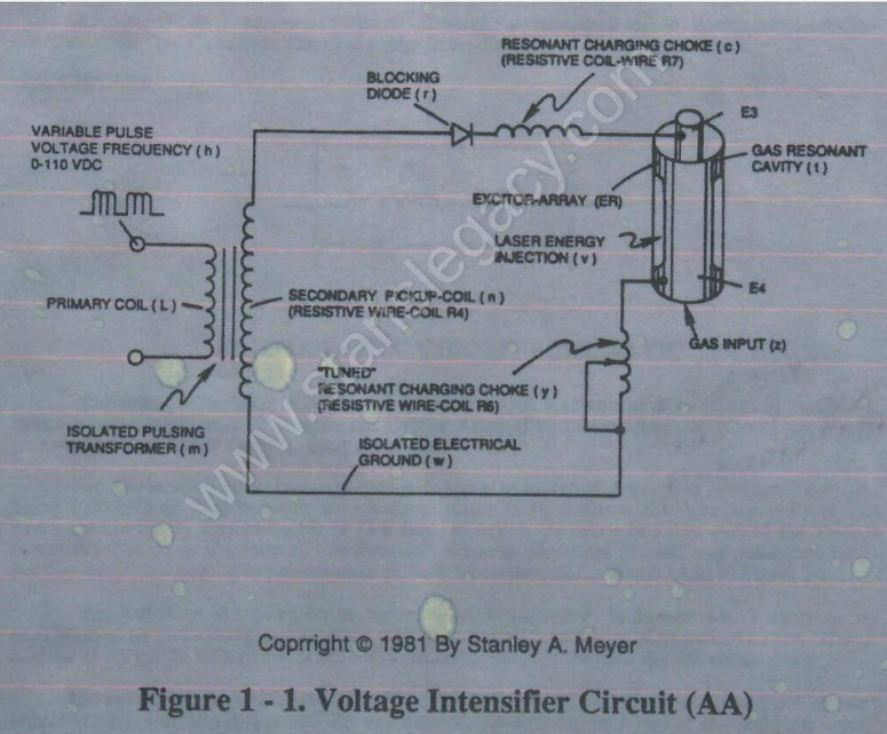
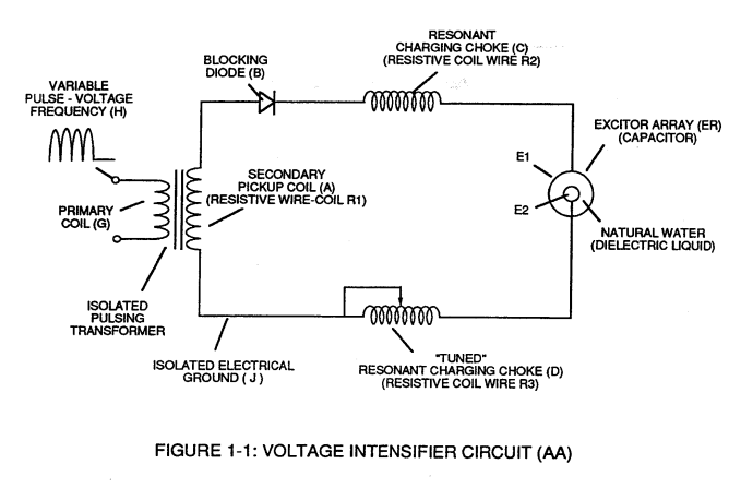
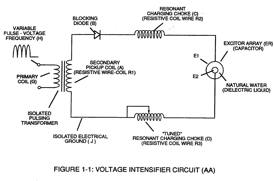
The primary coil is electrically isolated (no electrical connection between primary and secondary coil) to form Voltage Intensifier Circuit (AA) Figure (1-1). · Pulsing Transformer
-
(220) of Figure (18) · Water Fuel Injector (Taper Resonant Cavity Chamber)
-
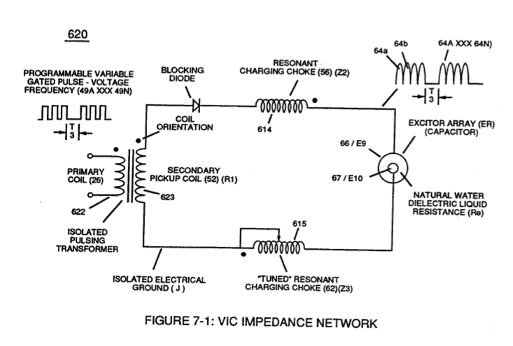
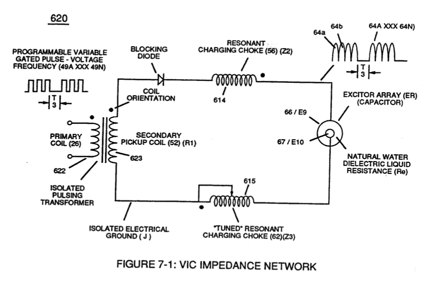
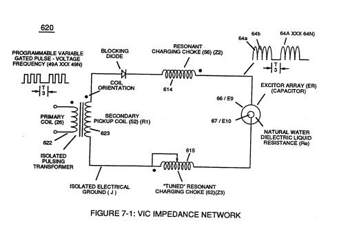
Voltage Intensifier Circuit (620) of Figure (7-1) · Instant Explosion of Water
-
(620) of Figure (7-1) · Instant Explosion of Water
-
(614) of Figure (7-1) · Inductance (FL)
-
Inductor (614) of Figure (7-1) · Inductance (FL)
-
(614) of (7-1) · Inductance (FL)
-
Figure (7-1) · Capacitance (Cd)
-
(620) of Figure (7-1) · Inductance Reactance (Rs - Cd - FL)
-
Capacitor (ER) of Figure (7-2) · Capacitance Reactance
-
Choke-Coil (62) of Figure (7-1) · Transformer Action
-
Carries this number · WFC 426 - Illustrations
-
(620) of Figure (7-1) · 8-6 - VIC Voltage Sync-Pulse Circuit
-
"Resonant Charging Choke" (56) of Figure (7-1) · Propagating Electrical Stress
-
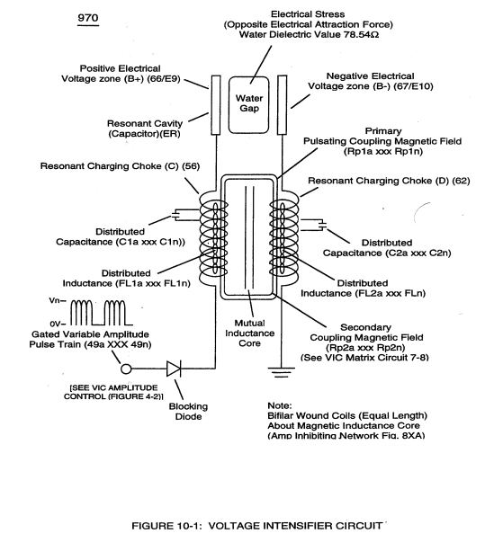
The programmable pulse-frequency (49a xxx 49n) of Figure (10-1) input is simply adjusted to tune-in to the dielectric property of the Water Molecule. · Propagating Electrical Stress
-
(620) of figure (7-1) · Voltage to Amp Differential Ratio
-
Carries this number · WFC 429 - Illustrations
-
Carries this number · Wobbling Effect
-
(970) of Figure (10-1) · VIC Switchover Circuit
-
LC CIRCUIT Figure 1-2. LC Circuit Schematic · CIRCUIT COMPONENT INTERACTION
-
Figure (1-2) · LC Circuit
-
Figure (1-3) · LC Circuit
-
The figure it sits on · Water Fuel Injection System
-
The figure it sits on · Electronic Circuit Design
-
The figure it sits on · Electronic Circuit Design
-
The figure it sits on · Differential Air-Gas Inlet Control
-
Water Fuel Injection System (10) of Figure (1) · Water Fuel Injector (Taper Resonant Cavity Chamber)
-
The figure it sits on · Water Fuel Injector (Taper Resonant Cavity Chamber)
-
Figure 1-3 · Amp Inhibiting Circuit Vs Voltage Enhancement
-
(650) of Figure (7-4) · Amp Inhibiting Circuit Vs Voltage Enhancement
-
Figure (4-5) · Water Fuel Injection System - Page 1
-
but, also prevents electron flow into destabilizing gas process (180), as so illustrated in Figure (4-5). · Water Fuel Injection System - Page 3
-
The figure it sits on · Energy Pumping Action
-
(520) in Figure (5-3) · Resonant Propagation
-
The figure it sits on · In Application of Usage
-
(520) of Figure (5-3) · In Application of Usage
-
(520) of Figure (5-3) · Solar Energy Actuator
-
The figure it sits on · Illustrations
-
Voltage Triggering Process (70) of Figure (4-5) · Voltage Intensifier Coil-Assembly
-
Hydrogen Fracturing Process (520) of Figure (5-3) · Voltage Intensifier Coil-Assembly
-
Figure (1-1) (Memo WFC 420) · Instant Explosion of Water
-
(628) of Figure (7-7) · Instant Explosion of Water
-
(16) of Figure (4-5) · Resistance (Rs)
-
(650) of Figure (7-4) · Resistance (Rs)
-
(620) of Figure (7-1) · Resistance (Rs)
-
(630) of Figure (7-2) · Inductance (FL)
-
The figure it sits on · Inductance (FL)
-
(670) of Figure (7-6) · Inductance (FL)
-
LC circuit of Figure (7-2) · Inductance (FL)
-
(650) of Figure (7-4) · Inductance (FL)
-
(650) of Figure (7-4) · Capacitance (Cd)
-
(670) of Figure (7-6) · Capacitance (Cd)
-
(670) of Figure (7-6) · Capacitance (Cd)
-
(627) of Figure (7-7) · Inductance Reactance (Rs - Cd - FL)
-
(E1/E2) of Figure (1-1) page (1-13) · Taper Resonant Capacitor (ERt)
-
The figure it sits on · Taper Resonant Capacitor (ERt)
-
Resonant Capacitor (140 -170) of Figure (7-6) · Capacitance Reactance
-
"Voltage Deflection" of Figure (7-4) · Capacitance Reactance
-
Figure (4-5) · Capacitance Reactance
-
Resonant Voltage Effect (670) of Figure (7-6) · Transformer Action
-
Opposite Electrical Attraction Force (SS' ~ 617 ~ RR' - T3 - SS' ~ 617 - RR') of Figure (7-4) · Electron Bounce Phenomenon
-
The figure it sits on · WFC 426 - Illustrations
-
The figure it sits on · WFC 426 - Illustrations
-
The figure it sits on · WFC 426 - Illustrations
-
The figure it sits on · WFC 426 - Illustrations
-
The figure it sits on · Dual Switchover Circuit
-
The figure it sits on · 8-2 - Traveling Voltage Wave-Guides
-
(520) of Figure (5-3) · 8-2 - Traveling Voltage Wave-Guides
-
(770) of Figure(8-1) · 8-2 - Traveling Voltage Wave-Guides
-
(770) of Figure (8-1) · 8-3 - Electrical Voltage-Pulse Wave-Transmission
-
(770 A) of Figure (8-1) · 8-4 - State Space (Sp)
-
(650) of Figure (7-4) · 8-4 - State Space (Sp)
-
(770 B) of Figure (8-1) · 8-4 - State Space (Sp)
-
(585) of Figure (8-1) · 8-4 - State Space (Sp)
-
Figure (4-5) · 8-5 - Energy Vectoring (Ev)
-
(770A) of Figure (8-1) · 8-5 - Energy Vectoring (Ev)
-
(612) of Figure (8-1) · 8-5 - Energy Vectoring (Ev)
-
(650) of Figure (7-4) · 8-6 - VIC Voltage Sync-Pulse Circuit
-
The figure it sits on · WFC 427 Illustrations
-
The figure it sits on · WFC 427 Illustrations
-
Energy Pumping Action (520) of Figure (5-3) · WFC Development Objectives
-
"Voltage Tickling of State Space" (770A) of Figure (8-1) · WFC Exhaust Air Reclaimer
-
"Voltage Tickling of State Space" (770B) of Figure (8-1) · WFC Exhaust Air Reclaimer
-
The figure it sits on · Propagating Electrical Stress
-
Figure (1-1) · Propagating Electrical Stress
-
Dynamic Electrical Charging Effect (612) of Figure (8-1) · Propagating Electrical Stress
-
The figure it sits on · Quartz Tube Configuration & Operational Parameters
-
... establishing variable Dynamic Electrical Charging Effect (612). · Quartz Tube Configuration & Operational Parameters
Where it is named · 26
WFC 417 — WFC 417 6×
-
Excitor-Array (ER)
Resonant Charging Choke (c) in series with Excitor-array (E1/E2) forms an inductor-capacitor circuit (LC) since the Excitor-Array (ER) acts or performs as an capacitor during pulsing operations.
-
The high Dielectric Properties (insulator to the flow of amps) of natural water (dielectric constant being 78.54 @ 25C) between the electrical plates (E1/E2) forms the capacitor (ER). Water now becomes part of the Voltage Intensifier Circuit in the form of "resistance" between electrical ground and pulse-frequency positive-potential...helping to prevent electron flow within the pulsing circuit (AA) of Figure 1-1).
-
Capacitance (ER)
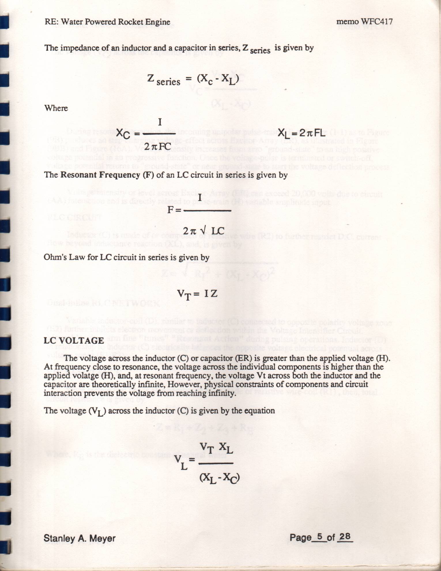
The Inductance (C) and Capacitance (ER) properties of the LC circuit is therefore "tuned" to resonance at a certain frequency. The Resonant Frequency can be raised or lowered by changing the inductance and/or the capacitance values. The established resonant frequency is, of course, independent of voltage amplitude, as illustrated in Figure 9BB as to Figure 16A.
-
Excitor-Array (ER)
(9B) produces an step-charging voltage-effect across Excitor-Array (ER), as illustrated in Figure (9BB) and Figure (16A). Voltage intensity increases from zero "ground-state" to an high positive voltage potential in an progressive function. Once the voltage-pulse is terminated or switch-off, voltage potential returns to "ground-state" or near ground-state to start the voltage deflection process
-
Excitor-Array (ER)
Voltage intensity or level across Excitor-Array (ER) can exceed 20,000 volts due to circuit (AA) interaction and is directly related to pulse-train (H) variable amplitude input.
-
Excitor-Array (ER)
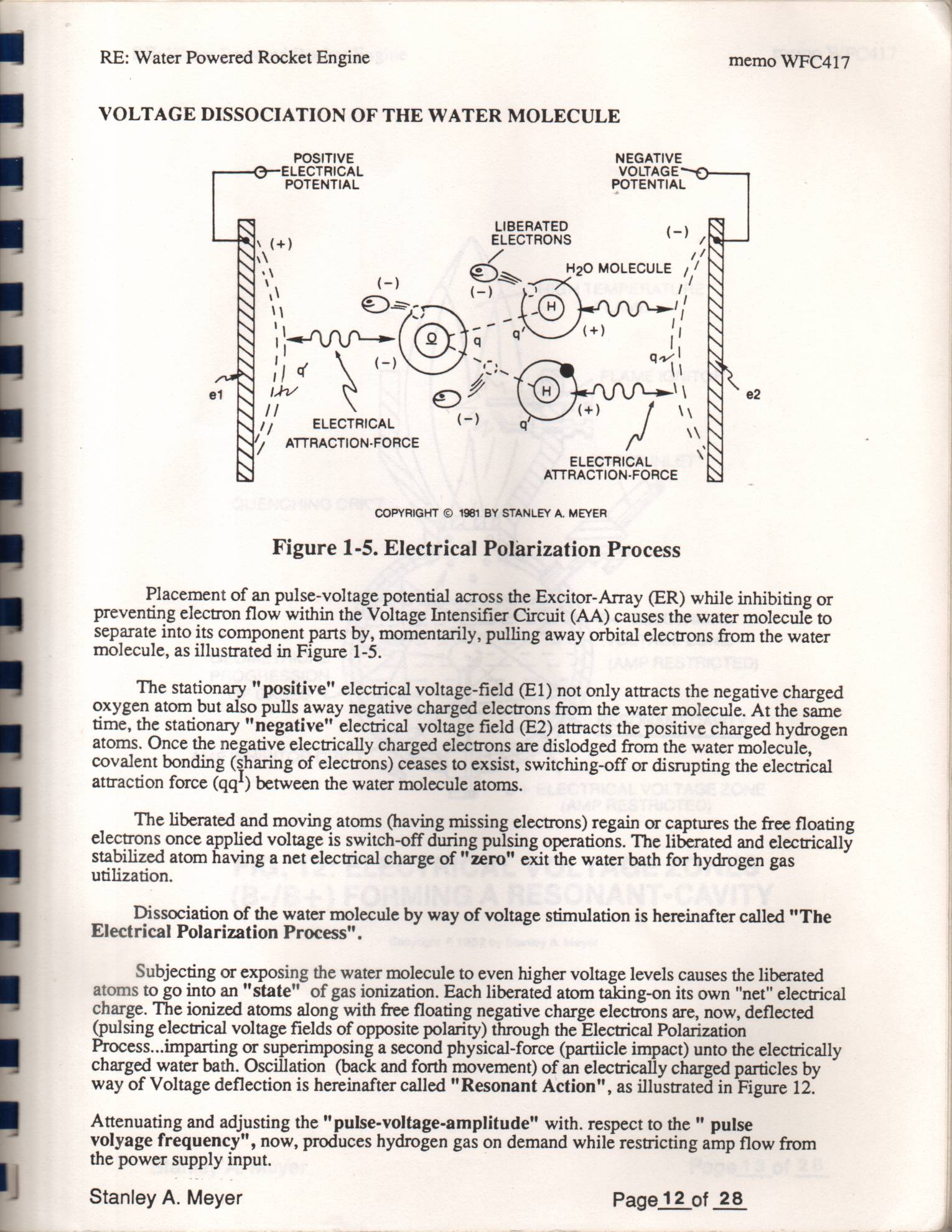
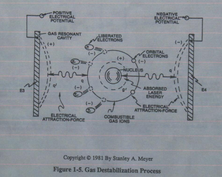
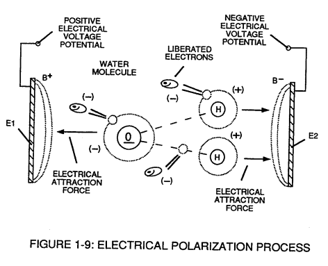
Placement of an pulse-voltage potential across the Excitor-Array (ER) while inhibiting or preventing electron flow within the Voltage Intensifier Circuit (AA) causes the water molecule to separate into its component parts by, momentarily, pulling away orbital electrons from the water molecule, as illustrated in Figure 1-5.
CIRCUIT COMPONENT INTERACTION 2×
-
Excitor-Array (ER)
Resonant Charging Choke (c) in series with Excitor-array (E3/E4) forms an inductor-capacitor circuit (LC) since the Excitor-Array (ER) of Gas Resonant Cavity (t) acts or performs as a capacitor during pulsing operations.
-
capacitor (ER)
The Dielectric Properties (insulator to the flow of amps) of Argon Gas (dielectric constant being 1.000545 @ 23°C) between the electrical plates (E3/E4) forms the capacitor (ER) of Gas Resonant Cavity (t).
Gas Destabilization Process 1×
-
Excitor-Array (ER)
Placement of a pulse-voltage potential across the Excitor-Array (ER) of Gas Resonant Cavity (t) while inhibiting or preventing electron flow within the Voltage Intensifier Circuit (AA) causes the Gas Atom of Argon (Ar) to become an positive charged ion by pulling away orbital electrons from the gas molecule or gas atom, as illustrated in Figure 1-5.
LC Circuit 2×
-
Excitor-Array (ER)
Resonant Charging Choke (C) in series with Excitor-array (E1/E2) forms an inductor-capacitor circuit (LC) since the Excitor-Array (ER) acts or performs as an capacitor during pulsing operations, as illustrated in Figure (1-2) as to Figure (1-1).
-
capacitor (ER)
The Dielectric Properties (insulator to the flow of amps) of natural water (dielectric constant being 78.54 @ 25c) between the electrical plates (E1/E2) forms the capacitor (ER).
LC Voltage 2×
-
Excitor-Array (ER)
During resonant interaction, the incoming unipolar pulse-train (H) of Figure (1-1) as to Figure (1-5) produces a step-charging voltage-effect across Excitor-Array (ER), as illustrated in Figure (1-3) and Figure (1-4).
-
Excitor-Array (ER)
Voltage intensity or level across Excitor-Array (ER) can exceed 20,000 volts due to circuit (AA) interaction and is directly related to pulse-train (H) variable amplitude input.
Voltage Dissociation of The Water Molecule 1×
-
Excitor-Array (ER)
Placement of a pulse-voltage potential across the Excitor-Array (ER) while inhibiting or preventing electron flow from within the Voltage Intensifier Circuit (AA) causes the water molecule to separate into its component parts by, momentarily, pulling away orbital electrons from the water molecule, as illustrated in Figure (1-9).
Capacitance (Cd) 1×
-
capacitor (ER)
Inherently, then, Resonant Cavity (720) of Figure (7-11) as to (650) of Figure (7-4) forms capacitor (ER) of Figure (7-1) when the dielectric liquid of water (85) is placed or injected between electrical conducting plates (E9/E10) while applied voltage Potential of opposite polarity (66/67) is directly e …
Inductance Reactance (Rs - Cd - FL) 2×
-
Inductance Reactance not only increases voltage across water-capacitor (ER) beyond applied Voltage Potential (626) of Figure (7-7) but, also, establishes "Impedance Field" (FL) across Inductors (L1-L2) of Figure (7-6) which acts and performs as Resonant Charging Chokes (614/ …
-
… so, establishes "Impedance Field" (FL) across Inductors (L1-L2) of Figure (7-6) which acts and performs as Resonant Charging Chokes (614/615) of Figure (7-1) once placed on opposite side of capacitor (ER) forming Resonant voltage Effect Circuit (670) of Figure (7-6), as illustrated in (620) of Figure (7-1) as to (690) of Figure (7-8).
In-Line Circuit Components 1×
-
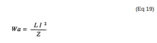
Lengthening Inductor (L1/L2) lengths applies an even higher Voltage Potential (66/67) across Resonant Capacitor (140 -170) (ER) since Inductance Reactance "Stores" Energy and, is expressed by:
Taper Resonant Capacitor (ERt) 1×
-
Capacitor (ER)
Capacitor (ER) is automatically formed when dielectric liquid of water (Re) is placed between Electrical Conducting Plates (E1/E2) of Figure (1-1) page (1-13) (Memo WFC 420).
Capacitance Reactance 3×
-
Capacitor (ER)
In terms of Component Reactance, Inductors (L1/L2) should always be larger than Capacitor (ER) of Figure (7-2) in order to maximize amp restriction to enhance "Voltage Deflection" (SS' - 617a xxx 617n - RR') of Figure (7-4) and, is expressed by :
-
Capacitor (ER)
Capacitor (ER) should remain relatively small due to the dielectric value of water to obtain maximum Thermal Explosive Energy-Yield (16a xxx 16n) of Figure (4-5) and subsequently establishing Quenching Circuit (370) of Figure (3-40) to prevent gas ignition inside traveling voltage wave-guide (590) of Figure (6-2) as to (730) of Figure (7-12)
Propagating Electrical Stress 2×
-
Dielectric Capacitor Gap (ER)
... thereby, preventing amp "in-fluxing" (discouraging electron arc over) across Dielectric Capacitor Gap (ER)(66/67) while Electrical Stress (ST-ST' - RU-RU') of Opposite Voltage Polarity (B+/B-) brings on Energy Priming Stage (520) of Figure (5-3) which is refer to, herein, as "Voltage Tickling of State Space."
-
Pulse-Voltage repetition rate sets up the step-up charging effect Figure (1-3) since the "Resonant Cavity" (Cp) functions as a "Capacitor" (ER) due to the dielectric value of the liquid (or gases) which becomes an integral part of the VIC Circuit, as so illustrated in (650) of Figure (7-4).
Optical Thermal Lens 1×
-
Voltage Zones (ER)
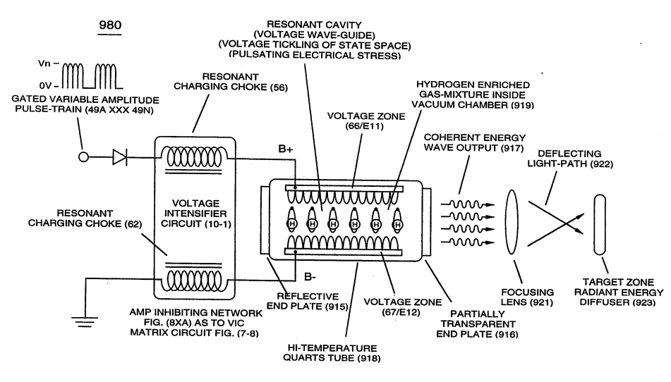
The Vacuum Chamber (Cv) containing the hydrogen gas atoms is composed of a high temperature quartz material (918) while Voltage Zones (ER) becomes Voltage Wave-Guides (770) of Figure (8-1) by the use of chemically inert T304 stainless steel material
Quartz Tube Configuration & Operational Parameters 1×
-
Voltage Zones (ER)
... thereby, establishing functional parameters of Optical Thermal Lens (980) of Figure (10-2) when Voltage Intensifier Circuit (VIC Circuit) (10-1) is electrically connected to Voltage Zones (ER) (66/Ell-67/E12).