(32) · also written as a run, 32a xxx 32n
Analog Signal
Also written analog voltage signal · nozzle-port · gas exit port · Exit Port · variable voltage amplitude control signal · battery electrical voltage potential · predetermined voltage level · battery voltage potential and 3 more
Where it is first named
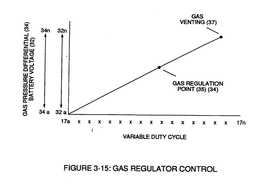
First, regulates car battery electrical voltage potential (32) of Figure (3-15) being applied to primary coil (26) of Figure (3-21); and secondly, regulates gas pressure of Fuel Cell (120) of Figure (3-22), as graphically depicted in Figure (3-15).
How it is written
- (32) 16×
- (32a xxx 32n) 4×
- (318 xxx 32n) 1×
- (32a xxx) 1×
32a xxx 32n is Meyer's shorthand for a run of the same thing: 32a is the first, 32n the last, and the x's stand for however many lie between. Every stage of the run is this one numeral.
Drawings 63
-
Figure (3-15) · Voltage Amplitude Control Circuit (50)
-
Figure (3-23) · Voltage Intensifier Circuit (60)
-
Figure (3-23) · Voltage Dynamics
-
reciprocating WFC Fuel-kits can be similar to Car design (340); · Aviation Application
-
Carries this number · WFC 422DA - Illustrations
-
Carries this number · WFC 422DA - Illustrations
-
Carries this number · WFC 422DA - Illustrations
-
Carries this number · Water Fuel Injection System
-
3-5 Outer Core Bobbin · Voltage Intensifier Coil Assembly
-
Carries this number · Voltage Intensifier Coil Assembly
-
Carries this number · Voltage Intensifier Coil Assembly
-
3-16 Mount Bar · Voltage Intensifier Coil Assembly
-
Carries this number · Electronic Circuit Design
-
Carries this number · Differential Air-Gas Inlet Control
-
Carries this number · Differential Air-Gas Inlet Control
-
Carries this number · Differential Air-Gas Inlet Control
-
(70) of Figure (3B) · Water Fuel Injector (Taper Resonant Cavity Chamber)
-
thereby, attenuating voltage amplitude (voltage intensity) beyond Secondary Coil (53) voltage levels (71), as illustrated in (220) of Figure (18). · Funneling Effect
-
Carries this number · Steam Resonator Assembly
-
Carries this number · Steam Resonator Assembly
-
Carries this number · Steam Resonator Assembly
-
Figure (4-1) · Water Fuel Injection System - Page 1
-
(230) of Figure (3-30) · In Application of Usage
-
(57) of Figure (6-2) · In Application of Usage
-
(Eq 32) hv /c · Solar Energy Actuator
-
Activation Process (590) of Figure (6-2) · Voltage Intensifier Coil-Assembly
-
(190) of Figure (3-23) · Tri - Coil Construction
-
(590) of Figure (6-2) · Capacitance (Cd)
-
Inductance Pulsing-Core (190) of Figure (3-23) · Inductance Reactance (Rs - Cd - FL)
-
Carries this number · Electron Bounce Phenomenon
-
(E9/10) of Figure (6-2) · Voltage Amplitude Switch-Off
-
Carries this number · WFC 427 Illustrations
-
"FullSystem" development (10) of Figure (4-1) · WFC Development Objectives
-
The figure it sits on · Laser Accelerator Assembly
-
Figure (3-5) · Acceleration Control Circuit (30)
-
Analog Voltage Circuit (40), as shown in Figure (3-5) · Acceleration Control Circuit (30)
-
Figure (3-5) · Acceleration Control Circuit (30)
-
Figure (3-5) · Analog Voltage generator (40)
-
Figure (3-21) · Voltage Amplitude Control Circuit (50)
-
Figure (3-1) · Voltage Amplitude Control Circuit (50)
-
Figure (3-21) · Voltage Intensifier Circuit (60)
-
The figure it sits on · Voltage Dynamics
-
To further prevent voltage fluctuation during resonant action, Phase Lock Loop technique of Pulse Indicator circuit (110) is utilized during pulsing operations. · Resonant Action
-
The figure it sits on · Gas Processor
-
Figure (3-1) · Laser Distributor
-
Figure (3-5) · Laser Distributor
-
Hydrogen Fuel-Gas Assembly (450) of Figure (3-1) · Operational Parameters
-
The figure it sits on · WFC 422DA - Illustrations
-
The figure it sits on · WFC 422DA - Illustrations
-
The figure it sits on · WFC 422DA - Illustrations
-
The figure it sits on · WFC 422DA - Illustrations
-
3-15 VIC Mount Plate · Voltage Intensifier Coil Assembly
-
The figure it sits on · Electronic Circuit Design
-
Figure (4-5) · Water Fuel Injection System - Page 1
-
but, also prevents electron flow into destabilizing gas process (180), as so illustrated in Figure (4-5). · Water Fuel Injection System - Page 3
-
The figure it sits on · In Application of Usage
-
Voltage Triggering Process (70) of Figure (4-5) · Voltage Intensifier Coil-Assembly
-
(16) of Figure (4-5) · Resistance (Rs)
-
(370) of Figure (3-40) · Taper Resonant Capacitor (ERt)
-
Quenching Circuit (370) of Figure (3-40) · Capacitance Reactance
-
Figure (4-5) · Capacitance Reactance
-
Figure (4-5) · 8-5 - Energy Vectoring (Ev)
-
The figure it sits on · WFC 427 Illustrations
Where it is named · 22
Voltage Amplitude Control Circuit (50) 10×
-
battery electrical voltage potential (32)
First, regulates car battery electrical voltage potential (32) of Figure (3-15) being applied to primary coil (26) of Figure (3-21); and secondly, regulates gas pressure of Fuel Cell (120) of Figure (3-22), as graphically depicted in Figure (3-15).
-
analog signal (32)
Each regulatory stage (27) and (28) works separately and independent of each other but are! electronically linked or coupled together to produce a common analog signal (32) having a predetermined voltage level (32a xxx), as further shown in Figure (3-15).
-
predetermined voltage level (32a xxx)
Each regulatory stage (27) and (28) works separately and independent of each other but are! electronically linked or coupled together to produce a common analog signal (32) having a predetermined voltage level (32a xxx), as further shown in Figure (3-15).
-
analog voltage signal (32)
Regulator stage (27) of circuit (50) converts battery voltage potential (29) of Figure (3-6) via electrical terminal (31) of Figure (3-5) as to Figure (3-6) into a analog voltage signal (32) of Figure (3-15) which corresponds to but is electrically isolated (crossover voltage from two separate power supplies) from incoming gas volume signal (23) of Figure (3-14), as shown in Figure (35).
-
Variable voltage range (32a xxx 32n)
Variable voltage range (32a xxx 32n) from one (1) up to twelve (12) volts (regulating battery voltage) is applied across primary coil (26) of Voltage Intensifier Circuit (60) of Figure (3-21).
-
analog signal (32)
If for example, Fuel Gas production is greater than demand, then, analog signal (32) is reduced to proper voltage level (35) (voltage level directly determines gas pressure via Resonant Action) required to maintain gas pressure (34).
-
analog signal (32)
Conversely, analog signal (32) is always allowed to exceed voltage level (35) during injection (36) of Figure (3-1) until gas-point (34) is reached.
-
linear voltage (32)
In cases where linear voltage (32) drops (descending value) below gas-point (35) then gas regulator stage (28) increases voltage amplitude (32a xxx 32n) (analog voltage) to voltage point (35).
-
voltage amplitude (32a xxx 32n)
In cases where linear voltage (32) drops (descending value) below gas-point (35) then gas regulator stage (28) increases voltage amplitude (32a xxx 32n) (analog voltage) to voltage point (35).
-
battery voltage potential (32a xxx 32n)
In terms of operability, Laser Accelerator Assembly (20) of Figure (3-5) is, now, attenuating battery voltage potential (32a xxx 32n) which is electrically connected to Voltage Intensifier Circuit (60) of Figure (3-5).
Voltage Intensifier Circuit (60) 2×
-
variable voltage amplitude control signal (318 xxx 32n)
By integrating and joining together variable voltage amplitude control signal (318 xxx 32n) of Figure (3-15) with variable controlled switch-gate (49a xxx 49n) of Figure (3-18) across primary coil (26) of Figure (3-22),
-
Analog voltage signal (32a xxx 32n)
Analog voltage signal (32a xxx 32n) of Figure (3-15) allows pulse train (51a xxx 51n) voltage amplitude (V0 xxx Vn) of Figure (3-19) to vary from one up to twelve volts (battery supply 28 of Figure 3-6 by attenuating Laser Accelerator circuit (10) of Figure (3-5) via Hydrogen Gas Control Circuit (100).
Water Fuel Injection System 3×
-
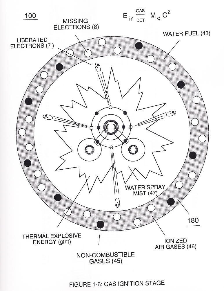
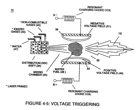
… gure (41) as to Figure (6) under control state (on demand) via electrical-static spark ignition (49 / 51) of Figure (3B)....releasing thermal explosive energy (gtnt) (16) passing beyond gas exit port (32) of Figure (3B), as further illustrated in Figure (2) as to Figure (1).
-
To elevate Energy-flame-temperature still further, help increase fluid-displacement (46/47) while maintaining or reducing the volume flow rate of non-combustible gases (45) during an increase of applied voltage amplitude (Vo x Vn) of Figure (32) as to Voltage Intensifier Circuit (110) of Figure (7) and Electron Extraction Circuit (120) of Figure (8).
-
nozzle-port (32)
The resultant energy-flame pattern is further maintained by allowing the ignited,compressed, and moving gases (29) of Figure (3B) to be projected to, pass through and beyond nozzle-port (32) under pressure due to gas expansion caused by thermal gas ignition.
Water Fuel Injection System - Page 1 1×
-
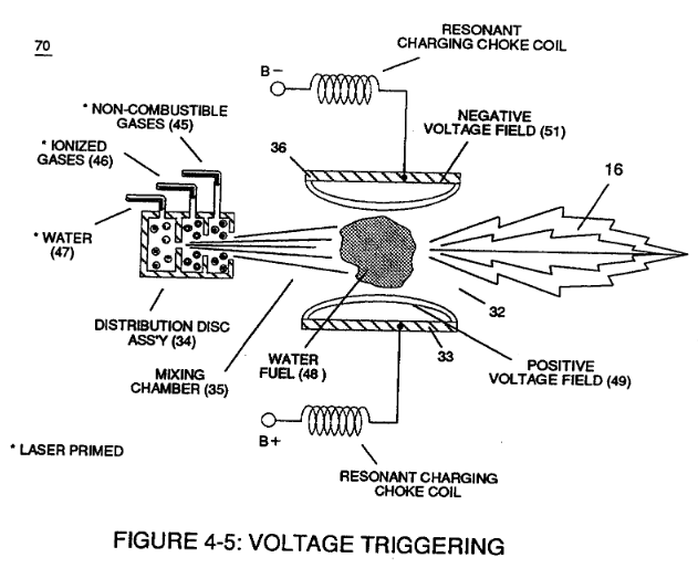
.... releasing thermal explosive energy (gtnt) (16) passing beyond gas exit port (32) of Figure (4-5), as further illustrated in Figure (4-2) as to Figure (4-1).
Water Fuel Injection System - Page 2 1×
-
nozzle-port (32)
The resultant energy-flame pattern is further maintained by allowing the ignited, compressed, and moving gases (29) of Figure (4-5) to be projected to, pass through and beyond nozzle-port (32) under pressure due to gas expansion caused by thermal gas ignition.
Water Fuel Injector 1×
-
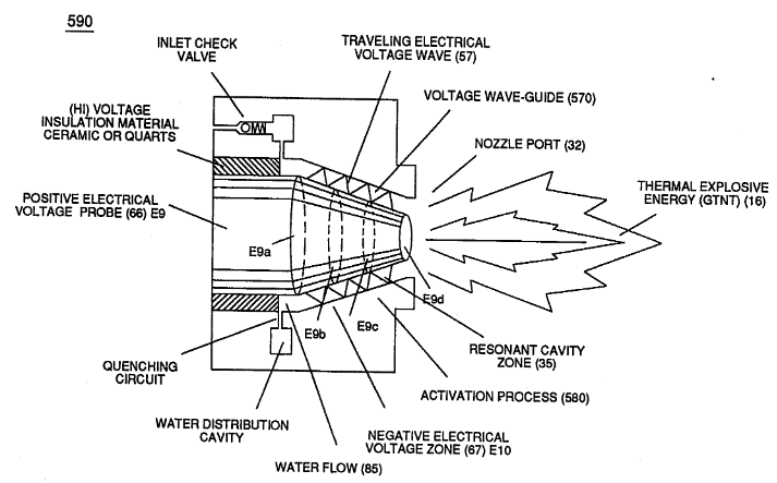
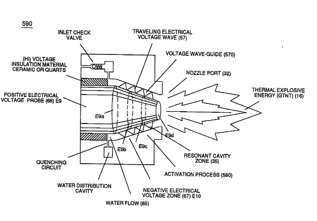
Together, parallel sides (E9 / El0) not only functions as a "voltage wave-guide" (570) but, also, acts and performs as a "voltage intensifier circuit" when applied gated pulse-frequency (64a xxx 64n) travels the length of conical cavity (570) toward exit port (32).
Taper Water Fuel Injectors 1×
-
Voltage wave-guide (570) allows the activation points (E9a xxx E9n) to transpire since wave-guide (570), now, functions as a Quenching Circuit (370) of Figure (3-40) to prevent gas ignition until the traveling gases (under static pressure) are exited out of and away from exit port (32) of Figure (6- 2)
Capacitance Reactance 1×
-
gas exit port (32)
which, when occurring at gas exit port (32) of Figure (4-5), spark-ignites expanding water gas-fuel (45/46/47) of Figure (4-5) during water inject cycle (70) of Figure (4-5)
Voltage Amplitude Switch-Off 1×
-
Exit Port (32)
Voltage levels of variance (Va xxx Vn) is achieved by simply switching-in or switching-out the member of Secondary Coil-cavities (505a xx 505n) (see 740 of Figure 7-13) in direct relationship to Taper Resonant Voltage surfaces (E9/10) of Figure (6-2) which acts and performs as a "Voltage Amplifier" when Compressional Wave-form (B) of Figure (7-12) is intensified at Exit Port (32) of Figure (6-2).
8-5 - Energy Vectoring (Ev) 1×
-
The "mode of operability" of determining the "Operational Parameters" of adjusting the thermal explosive energy (gtnt) exiting from nozzle-port (32) of Figure (4-5) as to (40) of Figure (4-2) is directly related to the characteristics of the applied Voltage Pulse Potential (Vpp) Wave-form (s) (Vpwt) and the geometrical configuration of Resonant Cavity (90) of Figure (4-7) as to (730) of Figure (7-12).