(720)
Taper Resonant Cavity
Also written Resonant Cavity · Tapered Voltage Wave-Guide · Taper Capacitor
Where it is first named
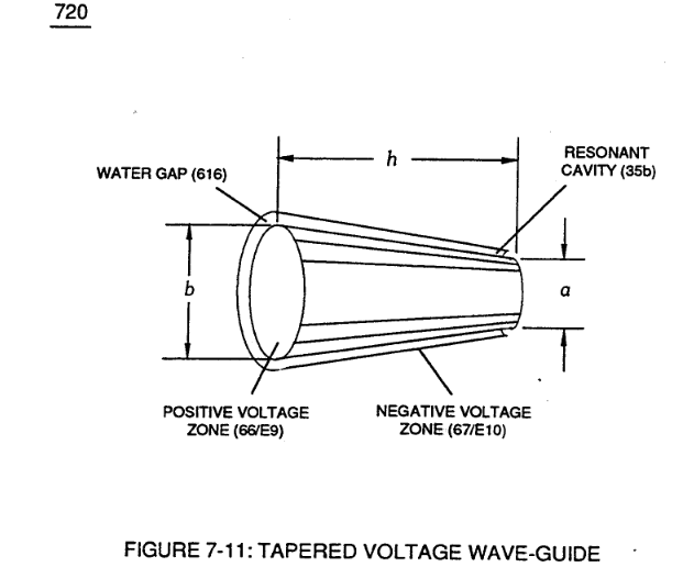
... releasing thermal explosive energy (gtnt) (16) of Figure (4-5) on demand from natural water (85) of Figure (3-26) since the dielectric value (Re) of (Eq.9) of Water Fuel (85) is further approximated in Capacitance Equation (Eq.22), as illustrated in (650) of Figure (7-4) as to Tapered Voltage Wave-Guide (720) of Figure (7-11)
How it is written
- (720) 11×
- (720, 616) 1× with (616) Water Gap
Drawings 16
-
(616) of Figure (7-11) · Instant Explosion of Water
-
(720) of Figure (7-11) · Inductance (FL)
-
(720, 616) of Figure (7-11) · Inductance (FL)
-
Capacitor (E9/E10) of Figure (7-11) · Inductance (FL)
-
(720) of Figure (7-11) · Capacitance (Cd)
-
diagram 720 of Figure 7-11 · Taper Resonant Capacitor (ERt)
-
Carries this number · WFC 426 - Illustrations
-
(720) of Figure (7-11) · 8-2 - Traveling Voltage Wave-Guides
-
(see diagram 720 of Figure 7-11) · Taper Resonant Capacitor (ERt)
-
(780A) Figure (8-2) · 8-2 - Traveling Voltage Wave-Guides
-
Figure (8-2) · 8-2 - Traveling Voltage Wave-Guides
-
(780 B) of Figure (8-2) · 8-4 - State Space (Sp)
-
(780 A/B/C) of Figure (8-2) · 8-4 - State Space (Sp)
-
Clipped Voltage Wave-form (780C) of Figure (8-2) · 8-5 - Energy Vectoring (Ev)
-
The figure it sits on · 8-6 - VIC Voltage Sync-Pulse Circuit
-
The figure it sits on · WFC 427 Illustrations
Where it is named · 12
Resistance (Rs) 1×
-
Tapered Voltage Wave-Guide (720)
... releasing thermal explosive energy (gtnt) (16) of Figure (4-5) on demand from natural water (85) of Figure (3-26) since the dielectric value (Re) of (Eq.9) of Water Fuel (85) is further approximated in Capacitance Equation (Eq.22), as illustrated in (650) of Figure (7-4) as to Tapered Voltage Wave-Guide (720) of Figure (7-11)
Inductance (FL) 4×
-
Taper Capacitor (720)
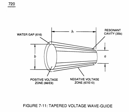
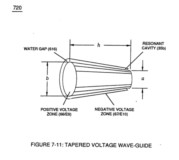
Resonant Charging Circuit (630) of Figure (7-2) being an LC Circuit is fanned when Inductor (614) of Figure (7-1) is electrically linked to Taper Capacitor (720) of Figure (7-11) in series arrangement.
-
(720) of Figure (7-11)
-
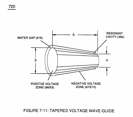
Capacitor (E9/E10) of figure (6-2) as to (720) of Figure (7-11) is formed when outer tapered surface (66) and inner tapered surface (67) forms Water-Gap (616) of Figure (7-11) as to Figure (590) of Figure (6-2) having placed there between Dielect …
-
(720, 616) of Figure (7-11)
Capacitance (Cd) 4×
-
Taper Resonant Cavity (720)
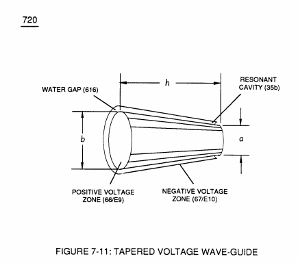
Capacitor (E9/E10) of Figure (7-1) as to Figure (650) of Figure (7-4) in direct relationship to Water Gap (616) becomes Taper Resonant Cavity (720) of Figure (7-11) as shown in (590) of Figure (6-2) since Water Gap (616) is occupied by a dielectric liquid (Re) as herein before identified as natural water (85) having no electrolyte added thereto
-
(720) of Figure (7-11)
-
Resonant Cavity (720)
Inherently, then, Resonant Cavity (720) of Figure (7-11) as to (650) of Figure (7-4) forms capacitor (ER) of Figure (7-1) when the dielectric liquid of water (85) is placed or injected between electrical conducting plates (E9/E10) while ap …
-
(720) of Figure (7-11)
8-2 - Traveling Voltage Wave-Guides 3×
-
… t an cylindrical axis of rotation having space-gap (35) there between and thus, fanning Cylindrical Resonant Cavity (730A) of Figure (7-12) as to (770A) of Figure (8-1) when space-gap (616) of Figure (720) exposes injected water bath (85) to unipolar pulse-oscillation of high voltage intensity of opposite polarity (67/66) as to (780) of Figure (8-2) which, in turn, propagates opposite electrical attrac …
-
... forming tubular voltage wave-guide (s) (570) of Figure (7-12) that, now, becomes the same physical configuration of Water Gap (616), as illustrated in (720) of Figure (7-11).
-
(720) of Figure (7-11)