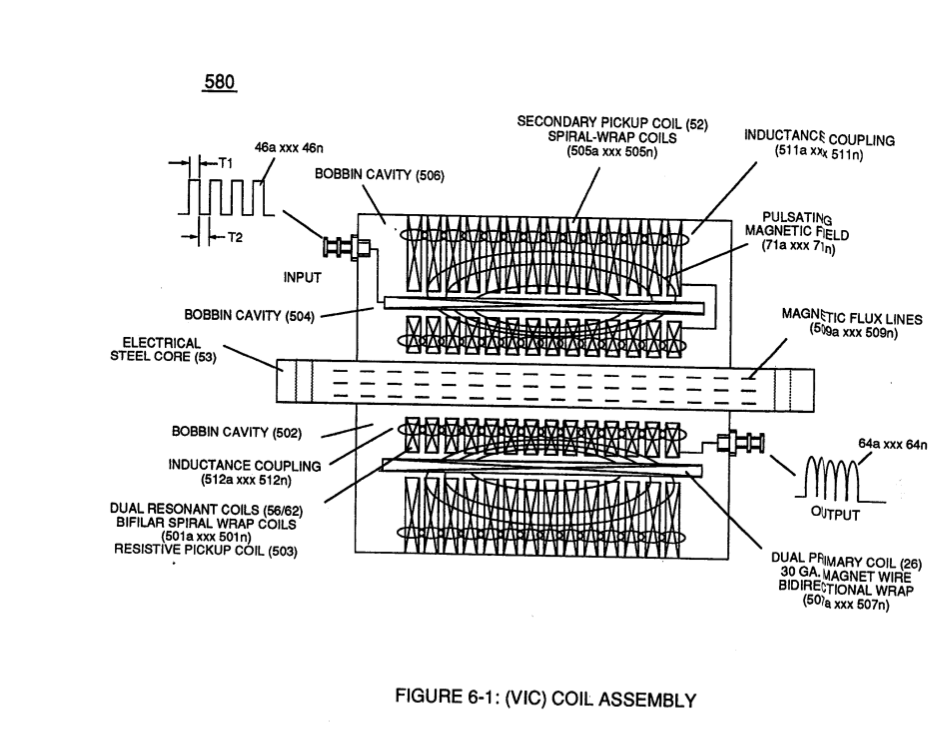
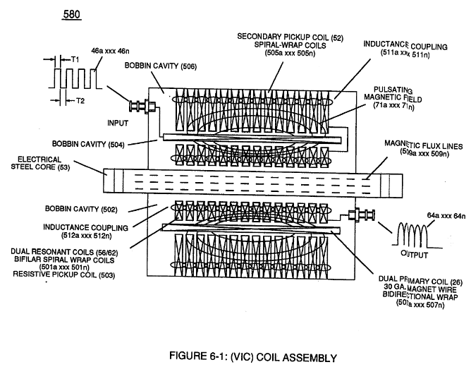
Figure (6-1)
Coil Assembly
How it is written
- (6-1) 33×
Drawings 5
-
coil-structures (580) of Figure (6-1) · Voltage Intensifier Coil-Assembly
-
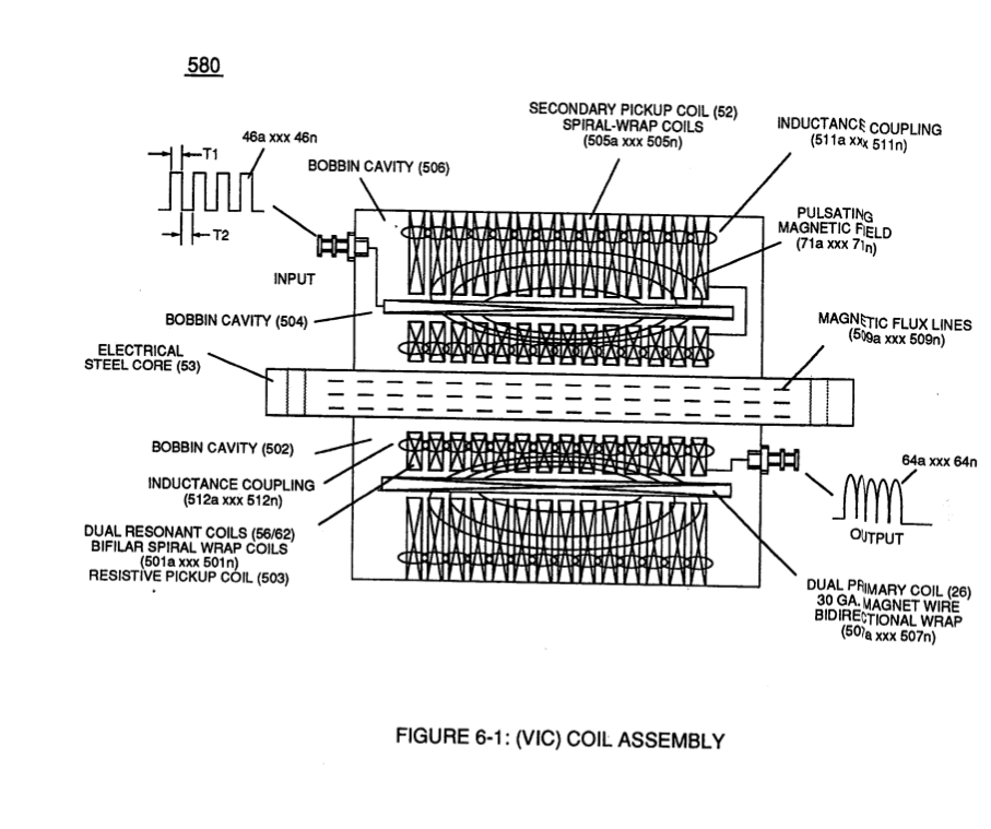
(580) of Figure (6-1) · Inductance (FL)
-
(580) of Figure (6-1) · Multi-layer Coil
-
(580) of Figure (6-1) (WFC memo 425) · 8-2 - Traveling Voltage Wave-Guides
-
(580) of Figure (6-1) · Voltage to Amp Differential Ratio
On this figure 24
- 53 Pulsing Core
- 56 Resonant Charging Choke
- 62 Resonant Charging Chokes
- 64 Pulse Train
- 71 Magnetic Field Coupling
- 85 Water Molecule
- 100 Hydrogen Fracturing Process
- 504 Primary Coil-Wrap
- 505 Secondary Coil-cavities
- 511 Inductance Coupling field
- 512 Inductance Coupling field
- 580 VIC Coil Assembly
- 614 Inductor
- 617 Molecular Polarization Alignment
- 619 Voltage Pulse Burst Wave
- 860 Amp Inhibitor Circuit
- L1 Inductor
- L2 Inductors
- Np —
- Rp1 Coupling Inductance
- Rp2 Mutual Inductance Fields
- V Voltage Amplitude
- VIC Resonant Cavity Voltage Intensifier Circuit
- Vn Voltage Potential
Where it is named · 33
Water Fuel Injector 2×
-
… RU - RU') of Figure (5-1) (Memo WFC 424) titled "Atomic Energy Balance of Water" is further enhanced by simply electrically interfacing voltage intensifier (VIC) circuit coil-assembly (580) of Figure (6-1) with 'Taper Resonant Cavity" (590) of Figure (6-2), as schematically illustrated in (60) of Figure (3-22) as to pulse core configuration (190) of Figure (3-23) (Memo WFC 422 DA) titled "WFC Hydrogen …
Voltage Intensifier Coil-Assembly 4×
Inductance (FL) 3×
-
(580) of Figure (6-1)
Capacitance (Cd) 2×
-
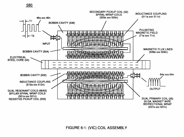
Inductor (614) and Inductor (615) of Figure (7-1) as to (670) of Figure (7-6) is wound or coil-wrapped (see multi-layer equation Eq. 20) in such a manner as to increase the magnetic flux intensity (D1a xxx D1n) of Figure (7-3) as to (580) as to Figure (6-1) in reference to (710) of Figure (7-10) between the turns (618a xxx 618n) of coil-wrap (640).
-
(580) as to Figure (6-1)
Inductance Reactance (Rs - Cd - FL) 5×
-
… levels (xxx Ve xxx Vf xxx Vn), primary electromagnetic coupling field (Rp) of Figure (7-8) transmitted by way of Inductance Pulsing-Core (190) of Figure (3-23) as to VIC Coil Assembly (580) of Figure (6-1) enters into and passes through both Inductors (L1/L2) simultaneously and offers not only further electron-flow restriction (Rp1/Rp2) to both Inductor Chokes (56/62) but automatically increases voltag …
-
VIC Coil Assembly (580) of Figure (6-1)
-
… paralleling and performing the same electromagnetic characteristic of copper wire when it comes to magnetic field reformation (Rp - Rp 1 - Rp2) of Figure (7-8), as further illustrated in electromagnetic coupling fields (71 - 511 - 512) of Figure (6-1) that encourages, brings-on, and perform Voltage Inducement Process (580) of Figure (6-1) as to (620) of Figure (7-1) without amp "influxing" (inhibiting amp flow) between Positive Voltage Potential ( …
-
… 1 - Rp2) of Figure (7-8), as further illustrated in electromagnetic coupling fields (71 - 511 - 512) of Figure (6-1) that encourages, brings-on, and perform Voltage Inducement Process (580) of Figure (6-1) as to (620) of Figure (7-1) without amp "influxing" (inhibiting amp flow) between Positive Voltage Potential (66) and Negative Voltage Potential (67) electrically applied across Resonant Cavities (14 …
-
Figure (6-1)
Multi-layer Coil 2×
-
(580) of Figure (6-1)
Transformer Action 9×
-
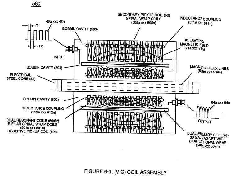
(53) of Figure (6-1)
-
(Ns) is the number of turns of wire that make up Secondary Coil-Wrap (505) of Figure (6-1),
-
(Ns) is the number of turns of wire for each bobbin cavity (505) of Figure (6-1) as to (710) of Figure (7-10) that are electrically connected in series arrangement (505a xxx 505n) to form Secondary Coil-Wrap (52),
-
(505) of Figure (6-1)
-
(505) of Figure (6-1)
-
(580) of Figure (6-1)
Mode of Operability 1×
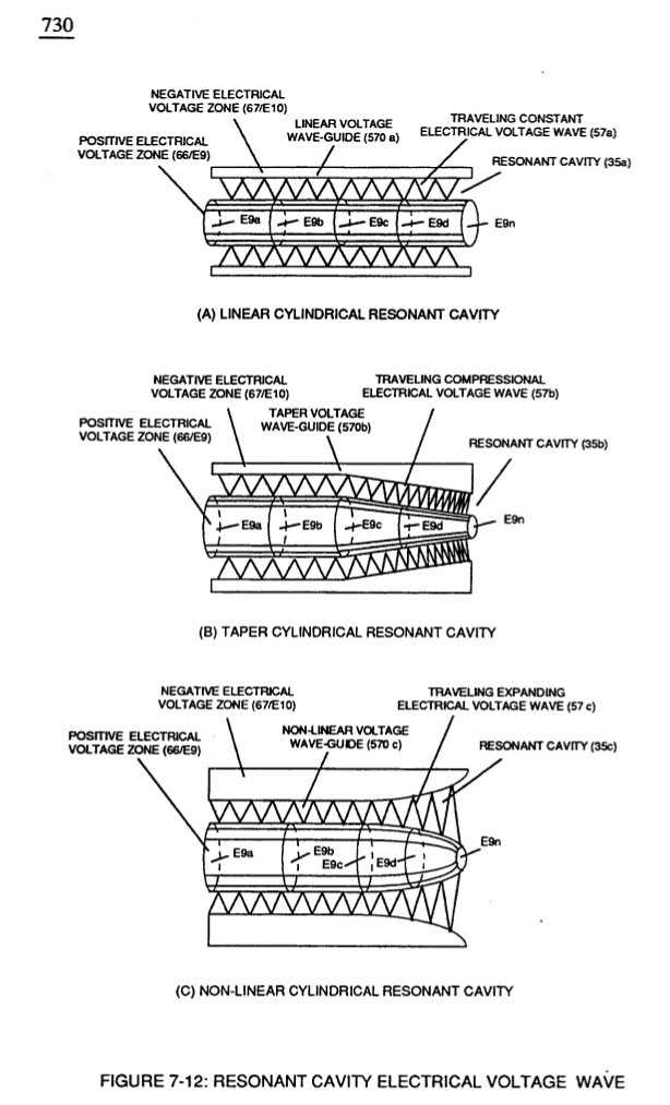
8-2 - Traveling Voltage Wave-Guides 2×
-
The dielectric property of water (85) (resistance to electron flow) in conjunction with VIC Coil Matrix Circuit (690) of Figure (7-8) (WFC memo 426) as to VIC Coil Assembly (580) of Figure (6-1) (WFC memo 425) ability to inhibit amp "influxing" (Electron Bounce Phenomenon EbP) during pulsing operations (49a xx 49n) allows voltage amplitude of pulse-frequency potential (T1a xxxT1n) as to (Vo …
-
(580) of Figure (6-1) (WFC memo 425)
8-6 - VIC Voltage Sync-Pulse Circuit 1×
Voltage to Amp Differential Ratio 2×
-
… 4) that are not only electrically connected in sequential order but likewise magnetically linked by Inductance Coupling field (511/512a xxx 511/512n), as so pictorially illustrated in (580) of Figure (6-1).
-
(580) of Figure (6-1)