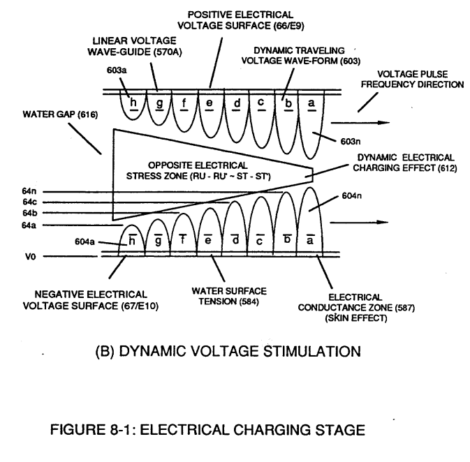
Figure (8-1)
Electrical Charging Stage
How it is written
- (8-1) 33×
Drawings 13
-
(770) of Figure(8-1) · 8-2 - Traveling Voltage Wave-Guides
-
(770) of Figure (8-1) · 8-3 - Electrical Voltage-Pulse Wave-Transmission
-
(770 A) of Figure (8-1) · 8-4 - State Space (Sp)
-
(770 B) of Figure (8-1) · 8-4 - State Space (Sp)
-
(585) of Figure (8-1) · 8-4 - State Space (Sp)
-
(770A) of Figure (8-1) · 8-5 - Energy Vectoring (Ev)
-
(612) of Figure (8-1) · 8-5 - Energy Vectoring (Ev)
-
Captioned as this figure · WFC 427 Illustrations
-
"Voltage Tickling of State Space" (770A) of Figure (8-1) · WFC Exhaust Air Reclaimer
-
"Voltage Tickling of State Space" (770B) of Figure (8-1) · WFC Exhaust Air Reclaimer
-
Dynamic Electrical Charging Effect (612) of Figure (8-1) · Propagating Electrical Stress
-
Captioned as this figure · Quartz Tube Configuration & Operational Parameters
-
... establishing variable Dynamic Electrical Charging Effect (612). · Quartz Tube Configuration & Operational Parameters
On this figure 30
- 49 Voltage Pulse frequency
- 64 Pulse Train
- 66 Positive Voltage Potential
- 67 Opposite Polarity
- 583 Voltage Pulse Train
- 585 Static Electrical Charging Effect
- 602 Voltage Pulse Train
- 603 —
- 604 —
- 612 Dynamic Electrical Charging Effect
- 619 Voltage Pulse Burst Wave
- 770 Static Voltage Stimulation
- 770A Voltage Tickling of State Space
- 770B Stimulation
- 780A Planar Unipolar Pulse Train
- 780B Convergent Point "Q"
- 780C Clipped Unipolar Pulse Train
- 918 Quartz Material
- Asa Atomic Snapping Action
- Cv Capacitor Vacuum-Gap
- E9 Capacitor
- E10 Capacitor
- ER Excitor-Array
- Es Voltage Gate-Pulse
- Qs Quiescent State
- T3 Unipolar Pulse-Train
- V Voltage Amplitude
- Vpb Voltage Amplitude Burst-Time
- Vpf Voltage Pulsing Cycle
- Vpp Voltage Peak Potential
Where it is named · 33
8-2 - Traveling Voltage Wave-Guides 6×
-
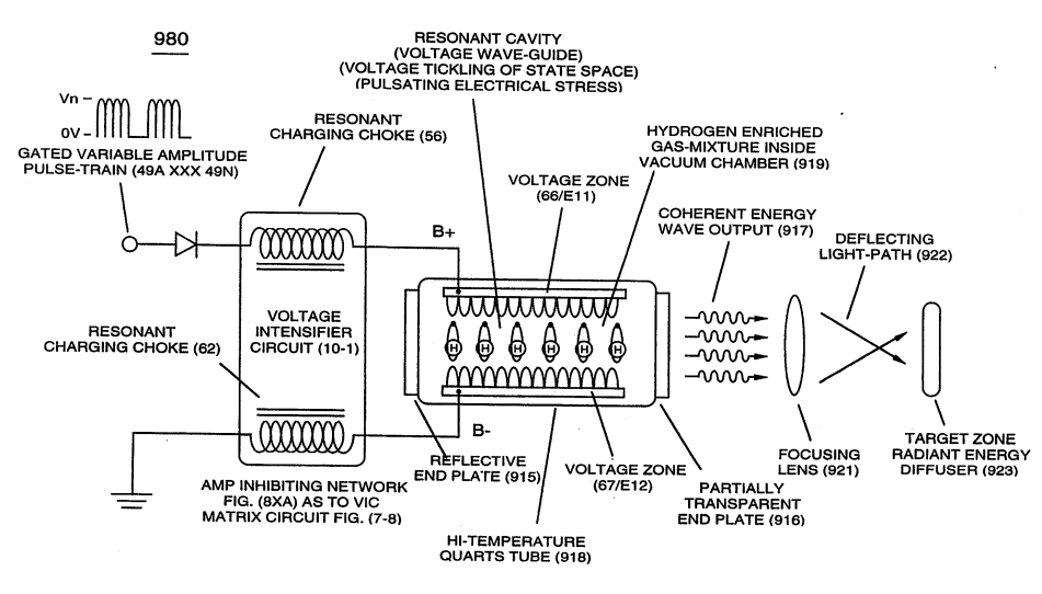
The formation of tubular Traveling Voltage Wave-guide (570a) of Figure (7-12) (WFC Memo 426) as to (770) of Figure (8-1) is physically formed when positive electrical voltage surface (66/E9) and negative electrical voltage surface (67/E10) are placed in parallel space relationship to form voltage surfaces (E9/E10) abou …
-
… o form voltage surfaces (E9/E10) about an cylindrical axis of rotation having space-gap (35) there between and thus, fanning Cylindrical Resonant Cavity (730A) of Figure (7-12) as to (770A) of Figure (8-1) when space-gap (616) of Figure (720) exposes injected water bath (85) to unipolar pulse-oscillation of high voltage intensity of opposite polarity (67/66) as to (780) of Figure (8-2) which, in turn, …
-
(770) of Figure (8-1)
-
Voltage Intensifier Matrix Circuit (690) of Figure (7-8) electrically connected with resistive liquid (85/Re) (forming Resonant Water Gap "Cp" of Figure 7-8) propagates the transmission of Traveling Voltage Wave-Form (57) of Figure (6-2) as to (770) of Figure(8-1) by the functional relationship of Circuit Resistance Equation (Eq 9) during programmable Voltage Pulsing operations (49a xxx 1'3 xxx 49n) of Figure (8-2).
-
(770) of Figure(8-1)
8-3 - Electrical Voltage-Pulse Wave-Transmission 2×
-
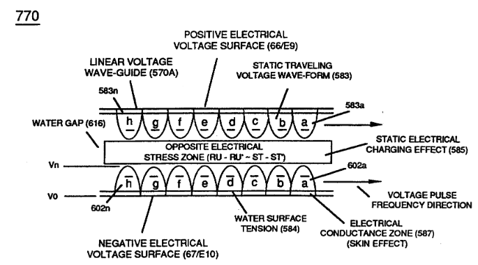
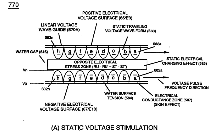
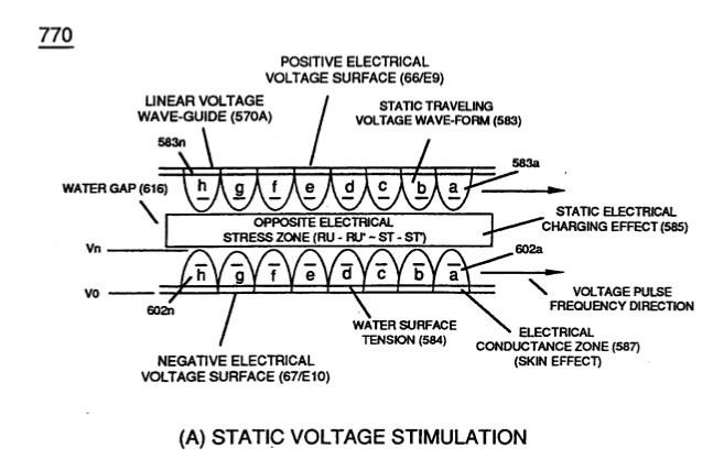
… 9) which, inactivated electrical-state, allows positive Voltage Pulse-Wave (583) to be duplicated in succession to form Voltage Pulse Train (66 - 583a xxx 583n), as illustrated in (770) of Figure (8-1).
-
(770) of Figure (8-1)
8-4 - State Space (Sp) 6×
-
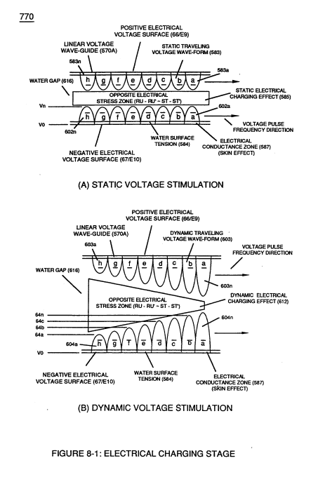
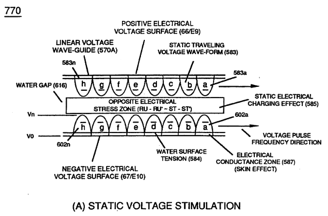
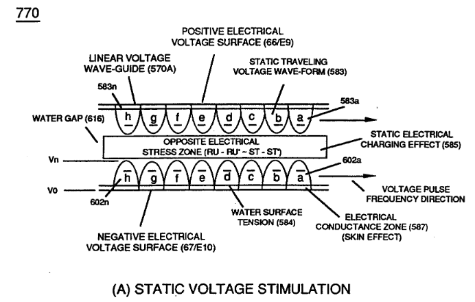
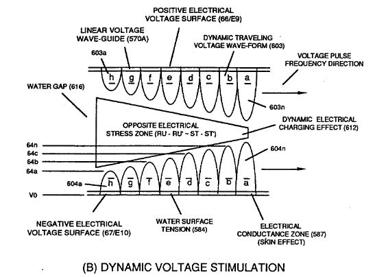
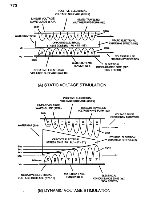
During the electrical-formation (66- Vpa/Vpb - 67- Vpa/Vpb) of each opposite Electrical Voltage-Wave (66-583 - 67-602), opposite electrical attraction force (RR' - SS') of Figure (7-4) is produced across water cap (Cp) of Figure (7-8) which, now, sets up and defines the conditions of “State Space," as illustrated in (770 A/B) of Figure (8-1) as to (650) of Figure (7-4).
-
(770 A) of Figure (8-1)
-
(770 B) of Figure (8-1)
-
… ic Snapping Action" (Asa) (the number of Voltage Pulse Fields Vpf occurring per unit of space-time) directly determines the resultant energy level of Static Electrical Charging Effect (585) of Figure (8-1) since “Particle Oscillation" is being used as a “Energy Generator" (EGpo), as so subscribed in memo (424) titled Atomic Energy Balance of Water as to the functional parameters associated with Dyn …
-
… Gpo), if Voltage Arc Line (Val) length is extended while Voltage Amplitude (xx 64a - 64b - 64c - Vn) is adjusted to higher Voltage Peak-Potential (Vpp) then greater atomic interaction (585) of Figure (8-1) (see WFC memo 424 titled Atomic Energy Balance of Water, once again) occurs when particle oscillation (Poe) of deflection of atomic mass (see 550 of Figure 5-8) (atom elongation) is electrically stre …
-
(585) of Figure (8-1)
8-5 - Energy Vectoring (Ev) 5×
-
… which combined together (Vpf + Vpb) Electrical Stress (Es) variances corresponds to the Voltage Pulse Shape of each synchronized opposite Voltage Pulse Wave (583 - 602) of (770A) of Figure (8-1) being produced during applied Voltage Pulse Operation (49a xxx 49n);
-
(770A) of Figure (8-1)
-
In the area of Voltage Sync-Wave (+/-) propagation, Unipolar Voltage Pulse Train (583/602a xxx 583/602) of (770A) of Figure (8-1), clipped Voltage Pulse Train (605/606a xxx 605/606n) of Figure (780C) of Figure (8-2), and Crossover Unipolar Pulse Train (607/608a xxx 607/608n) brings-on Static Voltage Stimulation (Vsvs) by which …
-
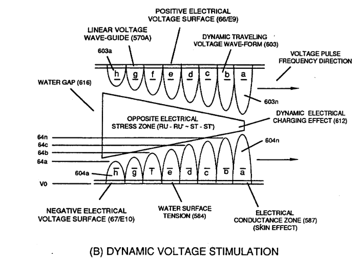
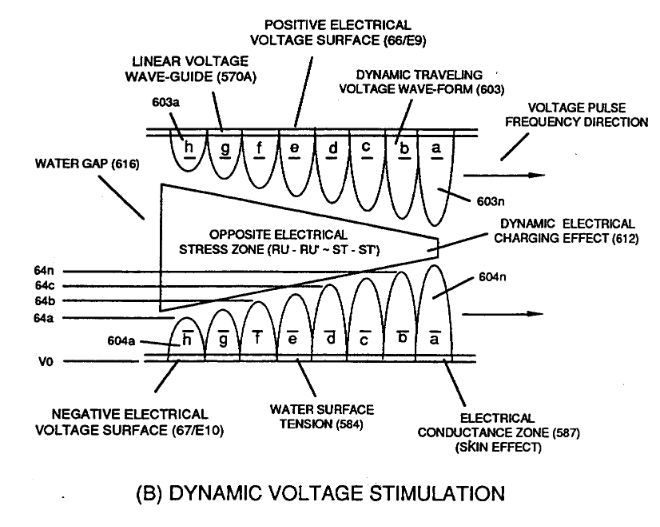
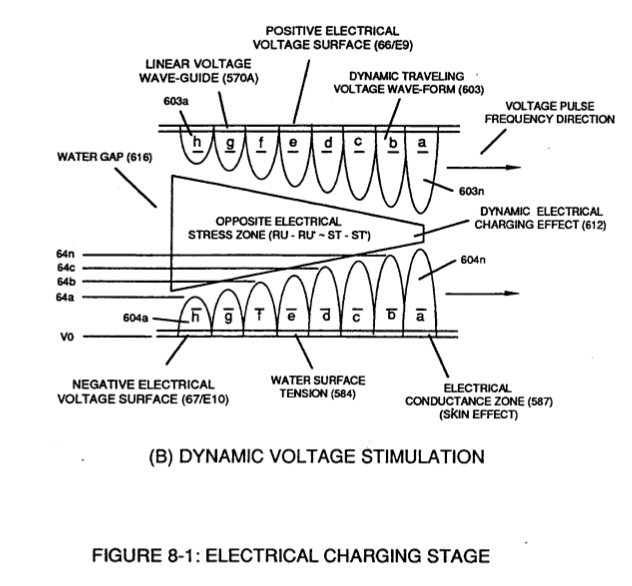
... producing Dynamic Electrical Charging Effect (612) of Figure (8-1) that increases Electrical Stress Pressure (Espa + Espb + Espc, and so on) continually during each gated voltage pulsing cycle (49a xxx T3 xxx 49n).
-
(612) of Figure (8-1)
8-6 - VIC Voltage Sync-Pulse Circuit 2×
-
Voltage Sync-Pulse Gated Frequency (583/602a xxx 583/602n) (603/604a xxx 603/604n) of Figure (8-1) as to (605/606a xxx 605/606n) (607/608a xxx 607/608n) (609/611a xxx 609/611n) of Figure (8-2)
-
… all, forming Voltage Pulse Burst Wave (619) as to Unipolar Pulse-Train (780A), Crossover Unipolar Pulse-Train (780B), and Clipped Unipolar Pulse Train (780C) as to Traveling Voltage Wave-Action (770) of Figure (8-1) of opposite voltage polarity (+/-) of equal Voltage-Pulse Amplitudes (+Vpp/- Vpp) are zero reference to electrical ground state (0V) by placing Amp Inhibitor Circuit (860) (Amp Inhibiting Coil 617, B …
WFC Exhaust Air Reclaimer 3×
-
… form, solid state electrical photon-light source (Light Emitting Diodes) (1100 xxx 116n) of Figure (3-33) replaces Sun Rays (539) of Figure (5-6) when "Voltage Tickling of State Space" (770 of Figure (8-1) acts as a "energy generator" by way of "particle oscillation" ~ of Figure ~ as to (~ .of Figure ~ to cause/activate Atomic Energy Level Adjustment (540) of Figure (5-7), as illustrated in Gas Process …
-
"Voltage Tickling of State Space" (770A) of Figure (8-1)
-
"Voltage Tickling of State Space" (770B) of Figure (8-1)
Propagating Electrical Stress 2×
-
Dynamic Electrical Charging Effect (612) of Figure (8-1)
Voltage to Amp Differential Ratio 4×
-
Opposite polarity Voltage Wave burst (1010) of Figure (10-5) as to Dynamic Voltage Stimulation (770B) of Figure (8-1) is simply produced when Programmable Variable Pulse-Width Pulse-Train Waveform (49a xxx 49n) is allowed to be electrically transmitted through and beyond Resonant Charging Chokes Stages (56/62a xx 56 …
-
Dynamic Voltage Stimulation (770B) of Figure (8-1)
-
The resultant ever increasing pulsating opposite electrical voltage fields (603/604a xxx 603/604n) of Figure (8-1) having superimposed thereon counter opposing Rippling Voltage-Surfaces (64/B+a xxx 64/B-n) [Dynamic Electrical Charging Effect (612) of Figure (8-1B)], now, set ups, causes, and applies ever increasing (rubberbanding effect) Pulsating Opposite Electrical Stress (RU-RU' - ST-ST') across Water Gap (Cp)
-
... see Dynamic Voltage Waveform (770) of Figure (8-1), once again.