(580)
VIC Coil Assembly
Also written voltage intensifier coil-assembly · Voltage Inducement Process · coil-structures · Bobbin Cavity
Where it is first named
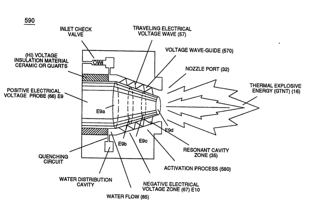
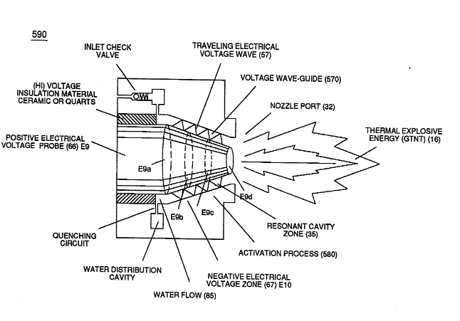
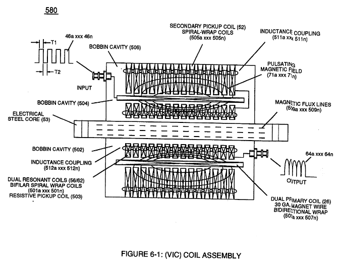
… ity (ST - ST' - RU - RU') of Figure (5-1) (Memo WFC 424) titled "Atomic Energy Balance of Water" is further enhanced by simply electrically interfacing voltage intensifier (VIC) circuit coil-assembly (580) of Figure (6-1) with 'Taper Resonant Cavity" (590) of Figure (6-2), as schematically illustrated in (60) of Figure (3-22) as to pulse core configuration (190) of Figure (3-23) (Memo WFC 422 DA) title …
How it is written
- (580) 24×
Drawings 18
-
Carries this number · WFC 421 - Illustrations
-
(57) of Figure (6-2) · In Application of Usage
-
Activation Process (590) of Figure (6-2) · Voltage Intensifier Coil-Assembly
-
coil-structures (580) of Figure (6-1) · Voltage Intensifier Coil-Assembly
-
(580) of Figure (6-1) · Inductance (FL)
-
(590) of Figure (6-2) · Capacitance (Cd)
-
(580) of Figure (6-1) · Multi-layer Coil
-
(E9/10) of Figure (6-2) · Voltage Amplitude Switch-Off
-
(580) of Figure (6-1) (WFC memo 425) · 8-2 - Traveling Voltage Wave-Guides
-
(580) of Figure (6-1) · Voltage to Amp Differential Ratio
-
(FI) of Figure (7-3b) · Instant Explosion of Water
-
Figure (7-3) · Inductance (FL)
-
(640) of Figure (7-3) · Capacitance (Cd)
-
Figure (7-3) · Multi-layer Coil
-
Distributed Capacitance (Cda xxx Cdn) of Figure (7-3) · Electron Bounce Phenomenon
-
The figure it sits on · WFC 426 - Illustrations
-
"bifilar" wrapped coils (Figure 7-3) · Propagating Electrical Stress
-
The figure it sits on · VIC Switchover Circuit
Where it is named · 24
Water Fuel Injector 1×
-
… ity (ST - ST' - RU - RU') of Figure (5-1) (Memo WFC 424) titled "Atomic Energy Balance of Water" is further enhanced by simply electrically interfacing voltage intensifier (VIC) circuit coil-assembly (580) of Figure (6-1) with 'Taper Resonant Cavity" (590) of Figure (6-2), as schematically illustrated in (60) of Figure (3-22) as to pulse core configuration (190) of Figure (3-23) (Memo WFC 422 DA) title …
Voltage Intensifier Coil-Assembly 4×
-
voltage intensifier coil-assembly (580)
Activation Process (590) of Figure (6-2) as to (100) of Figure (4-8) is achieved since amp flow is restricted to enter into Voltage Triggering Process (70) of Figure (4-5) by way of voltage intensifier coil-assembly (580) of Figure (6-1).
-
voltage intensifier coil-assembly (580) of Figure (6-1)
-
coil-structures (580)
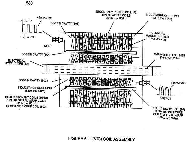
Inherently, the design parameters of coil-structures (580) of Figure (6-1) determines "Efficiency" (minimizing amp leakage) by which "Voltage Intensity of Opposite Potential" (600) of Figure (6-3) can perform work to trigger Hydrogen Fracturing Process (520) …
-
coil-structures (580) of Figure (6-1)
Inductance (FL) 3×
-
Bobbin Cavity (580)
Inductor (614) is an insulated wire wound in a spiral pathway around Bobbin Cavity (580) of Figure (6-1) to form Voltage Stepping Coil (710) of Figure (7-10) as to (580) of Figure (6-1).
-
Inductor (614) is an insulated wire wound in a spiral pathway around Bobbin Cavity (580) of Figure (6-1) to form Voltage Stepping Coil (710) of Figure (7-10) as to (580) of Figure (6-1).
-
(580) of Figure (6-1)
Capacitance (Cd) 3×
-
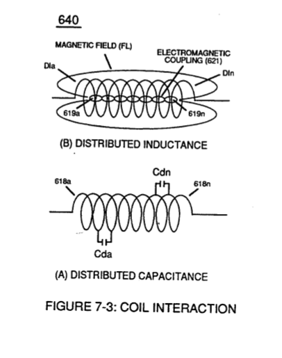
Inductor (614) and Inductor (615) of Figure (7-1) as to (670) of Figure (7-6) is wound or coil-wrapped (see multi-layer equation Eq. 20) in such a manner as to increase the magnetic flux intensity (D1a xxx D1n) of Figure (7-3) as to (580) as to Figure (6-1) in reference to (710) of Figure (7-10) between the turns (618a xxx 618n) of coil-wrap (640).
-
Figure (7-3) as to (580)
-
(580) as to Figure (6-1)
Inductance Reactance (Rs - Cd - FL) 3×
-
VIC Coil Assembly (580)
… plitude voltage levels (xxx Ve xxx Vf xxx Vn), primary electromagnetic coupling field (Rp) of Figure (7-8) transmitted by way of Inductance Pulsing-Core (190) of Figure (3-23) as to VIC Coil Assembly (580) of Figure (6-1) enters into and passes through both Inductors (L1/L2) simultaneously and offers not only further electron-flow restriction (Rp1/Rp2) to both Inductor Chokes (56/62) but automatically …
-
Voltage Inducement Process (580)
… mation (Rp - Rp 1 - Rp2) of Figure (7-8), as further illustrated in electromagnetic coupling fields (71 - 511 - 512) of Figure (6-1) that encourages, brings-on, and perform Voltage Inducement Process (580) of Figure (6-1) as to (620) of Figure (7-1) without amp "influxing" (inhibiting amp flow) between Positive Voltage Potential (66) and Negative Voltage Potential (67) electrically applied across Reson …
Multi-layer Coil 2×
-
VIC Coil Assembly (580)
… Figure (7-10) as to VIC Coil Assembly (580) of Figure (6-1) and, is expressed:
-
(580) of Figure (6-1)
Transformer Action 2×
-
VIC Coil Assembly (580)
VIC Coil Assembly (580) of Figure (6-1) as to (690) of Figure (7-8) in reference to Schematic Circuit (620) of Figure (7-1) is constructed in such a way as to rotate and position Inductor Coils (26 - 52 - 56 - 62) to be of the same electromagnetic polarity orientation, indicator mark (e)
-
(580) of Figure (6-1)
Mode of Operability 1×
-
VIC Coil Assembly (580)
The established "mode-of-operability" of VIC Coil Assembly (580) of Figure (6-1), now, allows Voltage Potential (Vn) of opposite voltage polarity (66/SS' - 67/RR') to increase and be attenuated up to and beyond 20 Kilovolts while inhibiting and restricting amp leakage in the milliamperes range
8-2 - Traveling Voltage Wave-Guides 2×
-
VIC Coil Assembly (580)
The dielectric property of water (85) (resistance to electron flow) in conjunction with VIC Coil Matrix Circuit (690) of Figure (7-8) (WFC memo 426) as to VIC Coil Assembly (580) of Figure (6-1) (WFC memo 425) ability to inhibit amp "influxing" (Electron Bounce Phenomenon EbP) during pulsing operations (49a xx 49n) allows voltage amplitude of pulse-frequency potential (T1a xx …
-
(580) of Figure (6-1) (WFC memo 425)
8-6 - VIC Voltage Sync-Pulse Circuit 1×
-
VIC Coil Assembly (580)
Amp Inhibiting Coil-Assembly (617) is made up of magnetic inductance Stainless Steel 430FR wire material wrapped around a closed-loop Induction Magnetic Core (619) which is a separate coil-unit (860) apart from VIC Coil Assembly (580) of Figure (6-1).
Voltage to Amp Differential Ratio 2×
-
… ) of Figure (10-4) that are not only electrically connected in sequential order but likewise magnetically linked by Inductance Coupling field (511/512a xxx 511/512n), as so pictorially illustrated in (580) of Figure (6-1).
-
(580) of Figure (6-1)