(650)
Capacitance Charging Effect
Also written Electrical Charging Effect
Where it is first named
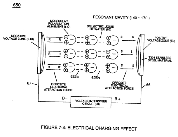
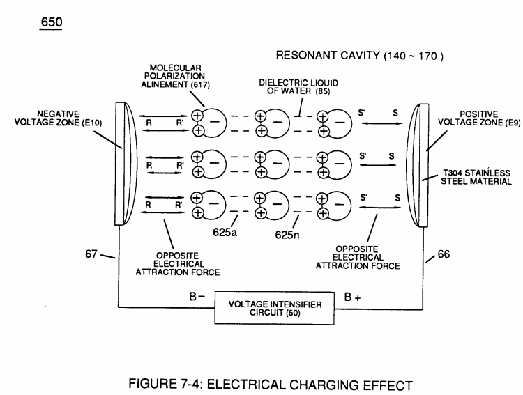
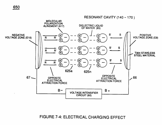
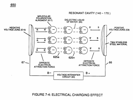
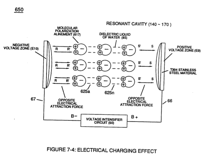
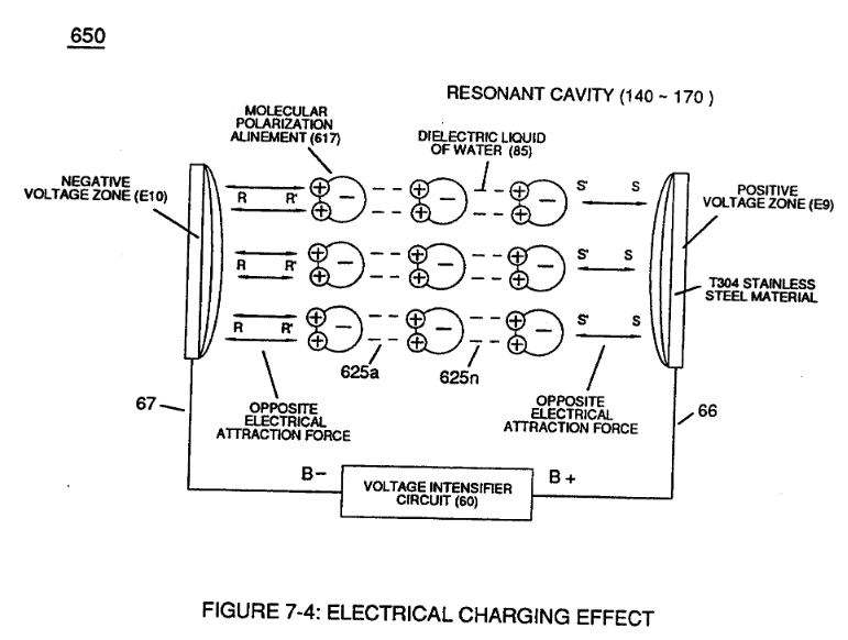
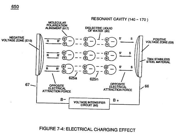
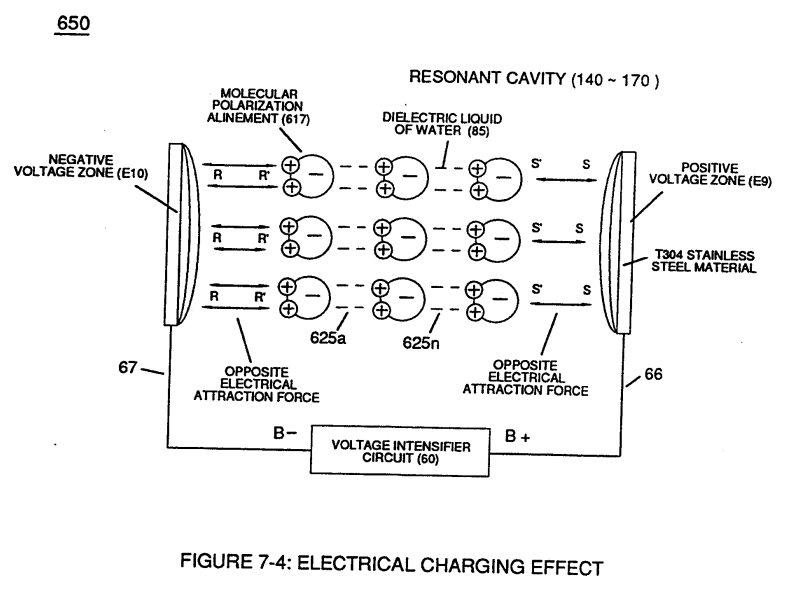
Pulse-Voltage repetition rate sets up the step-up electrical charging effect (Figure 1-3) since the "Resonant Cavity" functions as a Capacitor ER) due to the dielectric value (Resistance to amp flow) of water which becomes an integral part for the VIC Circuit, as so illustrated in (650) of Figure (7-4).
How it is written
- (650) 21×
Drawings 12
-
(650) of Figure (7-4) · Amp Inhibiting Circuit Vs Voltage Enhancement
-
(650) of Figure (7-4) · Resistance (Rs)
-
Carries this number · Inductance (FL)
-
(650) of Figure (7-4) · Inductance (FL)
-
(650) of Figure (7-4) · Capacitance (Cd)
-
"Voltage Deflection" of Figure (7-4) · Capacitance Reactance
-
Opposite Electrical Attraction Force (SS' ~ 617 ~ RR' - T3 - SS' ~ 617 - RR') of Figure (7-4) · Electron Bounce Phenomenon
-
Carries this number · WFC 426 - Illustrations
-
Carries this number · 8-2 - Traveling Voltage Wave-Guides
-
(650) of Figure (7-4) · 8-4 - State Space (Sp)
-
(650) of Figure (7-4) · 8-6 - VIC Voltage Sync-Pulse Circuit
-
Carries this number · Propagating Electrical Stress
Where it is named · 21
Amp Inhibiting Circuit Vs Voltage Enhancement 2×
-
Pulse-Voltage repetition rate sets up the step-up electrical charging effect (Figure 1-3) since the "Resonant Cavity" functions as a Capacitor ER) due to the dielectric value (Resistance to amp flow) of water which becomes an integral part for the VIC Circuit, as so illustrated in (650) of Figure (7-4).
-
(650) of Figure (7-4)
Resistance (Rs) 2×
-
... releasing thermal explosive energy (gtnt) (16) of Figure (4-5) on demand from natural water (85) of Figure (3-26) since the dielectric value (Re) of (Eq.9) of Water Fuel (85) is further approximated in Capacitance Equation (Eq.22), as illustrated in (650) of Figure (7-4) as to Tapered Voltage Wave-Guide (720) of Figure (7-11)
-
(650) of Figure (7-4)
Inductance (FL) 4×
-
Electrical Charging Effect (650)
… ced there between Dielectric Water Bath (85/Re), as schematically illustrated in matrix outline in (670) of Figure (7-6) as to (690) of Figure (7-8) and further detailed in Electrical Charging Effect (650) of Figure (7-4).
-
(650) of Figure (7-4)
-
... interacting Distributed Capacitance (Cda xxx Cdn) and Distributed Inductance (D1a xxx D1n) of Figure (7-3) of Inductor Coil (614) of (7-1) with "Electrical Charging Effect" brought on by the dielectric value of water bath (85/Re), as pictorially illustrated in (650) of Figure (7-4).
-
(650) of Figure (7-4)
Capacitance (Cd) 7×
-
Capacitor (E9/E10) of Figure (7-1) as to Figure (650) of Figure (7-4) in direct relationship to Water Gap (616) becomes Taper Resonant Cavity (720) of Figure (7-11) as shown in (590) of Figure (6-2) since Water Gap (616) is occupied by a dielectric liquid (Re) as herein before identified as natural water (85) having no electrolyte added thereto
-
Figure (650) of Figure (7-4)
-
... a resistive liquid (having an ohmic value of 78.54 ohms) that takes on an "Electrical Charge" when applied voltage Potential (66/67) of Figure (7-1) as to (650) of Figure (7-4) causes and sets up Molecular Polarization Alignment (617) of Figure (7-4) by way of electrical molecular rotation (opposite electrical attraction force to rotate and position particle alignment) of each water Molecule (85a - 85b - 85c - 85n). …
-
(650) of Figure (7-4)
-
Inherently, then, Resonant Cavity (720) of Figure (7-11) as to (650) of Figure (7-4) forms capacitor (ER) of Figure (7-1) when the dielectric liquid of water (85) is placed or injected between electrical conducting plates (E9/E10) while applied voltage Potential of op …
-
… ing plates (E9/E10) while applied voltage Potential of opposite polarity (66/67) is directly exposed to Water Molecules (85a xxx 85n), as depicted in Taper Resonant Cavity (590) of Figure (6-2) as to (650) of Figure (7-4).
-
(650) of Figure (7-4)
8-4 - State Space (Sp) 2×
-
During the electrical-formation (66- Vpa/Vpb - 67- Vpa/Vpb) of each opposite Electrical Voltage-Wave (66-583 - 67-602), opposite electrical attraction force (RR' - SS') of Figure (7-4) is produced across water cap (Cp) of Figure (7-8) which, now, sets up and defines the conditions of “State Space," as illustrated in (770 A/B) of Figure (8-1) as to (650) of Figure (7-4).
-
(650) of Figure (7-4)
8-6 - VIC Voltage Sync-Pulse Circuit 2×
-
Capacitance Charging Effect (650)
To ensure and maintain Capacitance Charging Effect (650) of Figure (7-4) across Water-Gap (Cp) of (7-8) during applied pulsing operations (49a xxx 49n), Crossover Voltage Wave-Form (780B) as to (780C) of Figure (8-2) is generally utilized by not allowing C …
-
(650) of Figure (7-4)
Propagating Electrical Stress 1×
-
Pulse-Voltage repetition rate sets up the step-up charging effect Figure (1-3) since the "Resonant Cavity" (Cp) functions as a "Capacitor" (ER) due to the dielectric value of the liquid (or gases) which becomes an integral part of the VIC Circuit, as so illustrated in (650) of Figure (7-4).
VIC Switchover Circuit 1×
-
The resultant pulsating electrical stress (S-S' /R-R) penetrates the liquid bath of water since the water bath takes on an electrical charge when the rotational spin (1019) of the water molecule (s) occurs to bring about bipolar alignment of the water molecule comprising water bath (68) during each and every reversing voltage pulsing cycle (B+/O - B-/O - OIB+ - OIB-), as so illustrated in (650) of Figure (7-4).