(70)
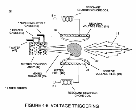
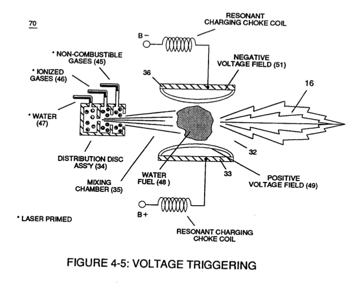
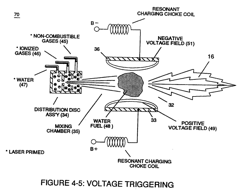
Voltage Triggering Process
Also written Circuit · Variable pulse frequency generator · Pulse Frequency Generator · pulse generator
Where it is first named
Incoming clock pulse (21a xxx 21n) of Figure (3-16) originating from Pulse Frequency Generator (70) of
How it is written
- (70) 18×
Drawings 34
-
Figure (3-5) · Acceleration Control Circuit (30)
-
Analog Voltage Circuit (40), as shown in Figure (3-5) · Acceleration Control Circuit (30)
-
Figure (3-5) · Acceleration Control Circuit (30)
-
Figure (3-5) · Analog Voltage generator (40)
-
Figure (3-5) · Laser Distributor
-
Carries this number · WFC 422DA - Illustrations
-
3-6 Pulsing Core · Voltage Intensifier Coil Assembly
-
3-8 Multi-Coil Spool · Voltage Intensifier Coil Assembly
-
Carries this number · Voltage Intensifier Coil Assembly
-
Carries this number · Electronic Circuit Design
-
Carries this number · Differential Air-Gas Inlet Control
-
(70) of Figure (3B) · Water Fuel Injector (Taper Resonant Cavity Chamber)
-
Voltage Triggering Process (70) of Figure (4-5) · Voltage Intensifier Coil-Assembly
-
(16) of Figure (4-5) · Resistance (Rs)
-
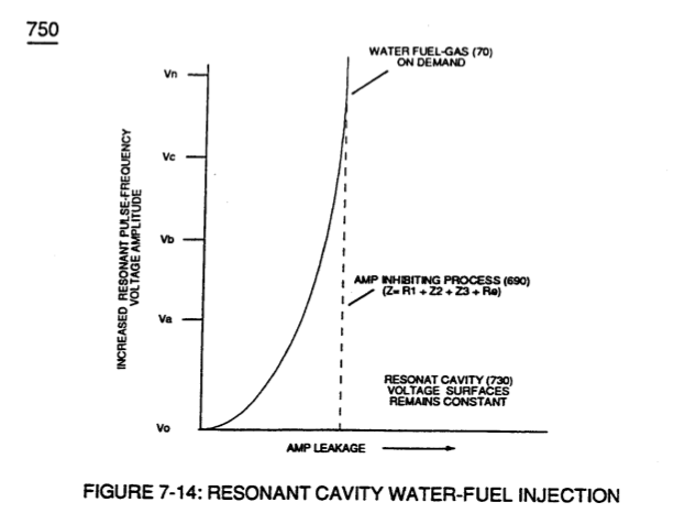
(750) of Figure (7-14) · Inductance (FL)
-
(750) of Figure (7-14) · Capacitance (Cd)
-
(750) of Figure (7-14) · Inductance Reactance (Rs - Cd - FL)
-
Figure (4-5) · Capacitance Reactance
-
Voltage Graph (750) of Figure (7-14) · Electron Bounce Phenomenon
-
(820B) of Figure (8-6) · 8-7 - Application of Usage
-
(820C) of Figure (8-6) · 8-7 - Application of Usage
-
Carries this number · WFC 427 Illustrations
-
Voltage Performance Graph (750) of Figure (7-14) · Voltage to Amp Differential Ratio
-
Figure (3-16) · Acceleration Control Circuit (30)
-
Figure (3-16) · Variable Pulse Frequency Generator (70)
-
The figure it sits on · Laser Distributor
-
The figure it sits on · WFC 422DA - Illustrations
-
3-5 Outer Core Bobbin · Voltage Intensifier Coil Assembly
-
3-16 Mount Bar · Voltage Intensifier Coil Assembly
-
The figure it sits on · Electronic Circuit Design
-
Figure (4-5) · Water Fuel Injection System - Page 1
-
but, also prevents electron flow into destabilizing gas process (180), as so illustrated in Figure (4-5). · Water Fuel Injection System - Page 3
-
The figure it sits on · In Application of Usage
-
Figure (4-5) · 8-5 - Energy Vectoring (Ev)
Where it is named · 18
Acceleration Control Circuit (30) 1×
-
Pulse Frequency Generator (70)
Incoming clock pulse (21a xxx 21n) of Figure (3-16) originating from Pulse Frequency Generator (70) of
Variable Pulse Frequency Generator (70) 2×
-
Circuit (70)
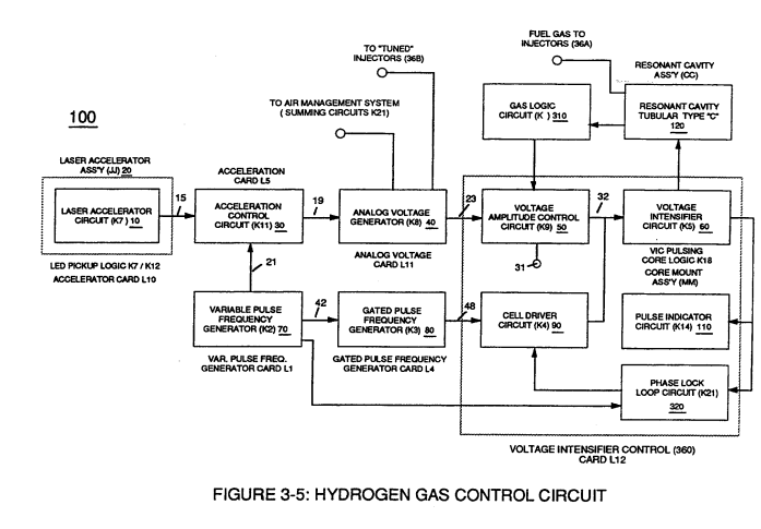
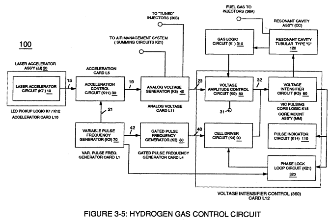
Circuit (70) of Figure (3-5) is a multi pulse-frequency generator which produces several clock pulses (simultaneously) having different pulse-frequency but maintaining a 50% duty cycle pulse (39) configuration, as illustrated in Figure (3-16).
-
Circuit (70)
Circuit (70) also produces another independent and separate clock signal (41a xxx 41n) which is electrically transmitted to and become incoming clock signal (42) for Gated Pulse Frequency Generator Circuit (80) of Figure (3-5).
Gated Pulse Frequency generator (80) 1×
-
pulse generator (70)
Pulse train (44a xxx 44n) is exactly the same as pulse train (41a xxx 41n) and its established pulse frequency (number of pulse cycles per unit of time) changes uniformly when pulse generator (70) of Figure (3-5) is calibrated and adjusted for system operations.
Voltage Intensifier Circuit (60) 1×
-
Variable pulse frequency generator (70)
Variable pulse frequency generator (70) of Figure (3-5) varies and adjusts pulse frequency (63) (50% duty cycle pulse) while gated pulse frequency generator (80) of Figure (3-5) varies and adjusts pulse width (54a xxx 54n).
Water Fuel Injector (Taper Resonant Cavity Chamber) 2×
-
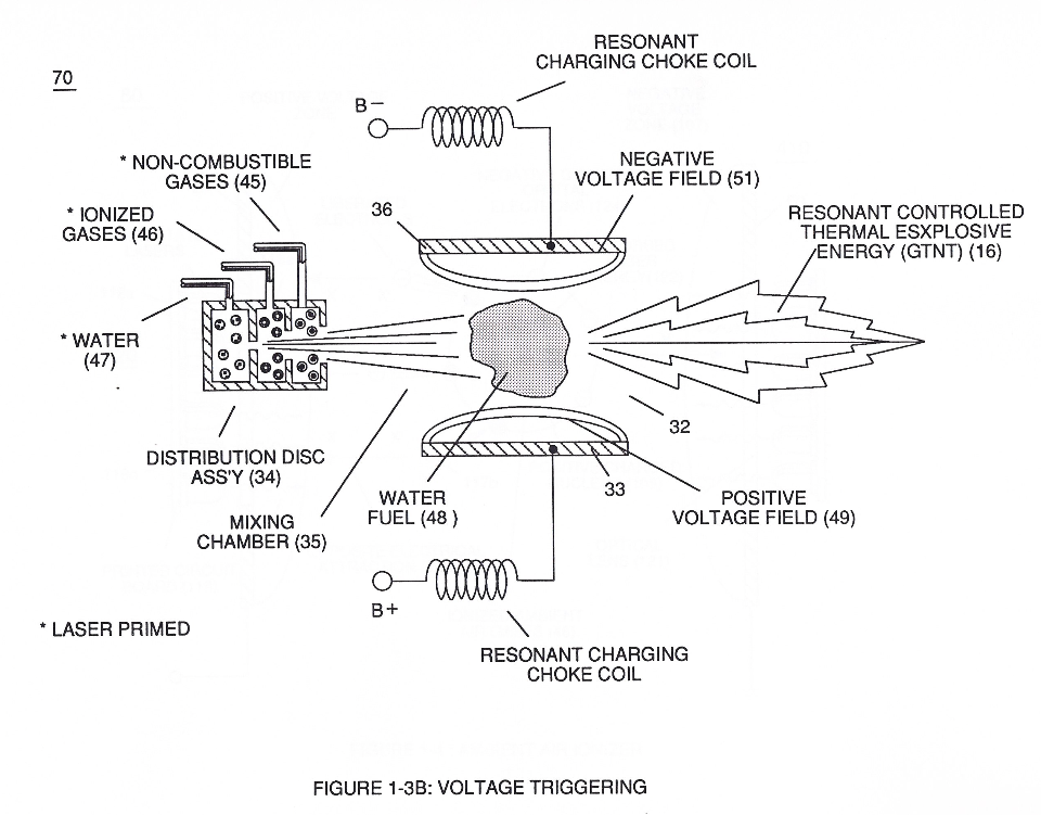
The injected water fuel-droplets (48a xxx 48n), now, surrounds outer surface area of exposed positive probe (33) while entering into Taper Resonant Cavity (180), as illustrated in (70) of Figure (3B) as to Figure (14).
-
(70) of Figure (3B)
In Application of Usage 1×
-
The Hydrogen Fracturing Process (390) of Figure (3-42) simply triggers and releases atomic energy (gtnt) from natural water (85) of Figure (3-26) by retarding and preventing the reformation of the water molecule being subjected to sub-critical state (520) of Figure (5-3) during thermal gas ignition (100) of Figure (4-8) as to (70) of Figure (4-5).
Taper Water Fuel Injectors 1×
-
... producing thermal explosive energy-yield (16), as further illustrated in (70) of Figure (4-5) titled "Voltage Triggering".
Voltage Intensifier Coil-Assembly 2×
-
Voltage Triggering Process (70)
Activation Process (590) of Figure (6-2) as to (100) of Figure (4-8) is achieved since amp flow is restricted to enter into Voltage Triggering Process (70) of Figure (4-5) by way of voltage intensifier coil-assembly (580) of Figure (6-1).
-
Voltage Triggering Process (70)
Voltage Triggering Process (70) of Figure (4-5)
Capacitance Reactance 1×
-
which, when occurring at gas exit port (32) of Figure (4-5), spark-ignites expanding water gas-fuel (45/46/47) of Figure (4-5) during water inject cycle (70) of Figure (4-5)
Electron Bounce Phenomenon 4×
-
... triggering Hydrogen Fracturing Process (90) of Figure (5-5) as to (100) of Figure (4-8) ... instantly releasing thermal explosive energy (gtnt) (16) from Water (85) on demand, as illustrated in Taper Resonant Cavity (590) of Figure (6-2) as to (70) of Figure (4-5).
-
(70) of Figure (4-5)
-
... therefore, producing a physical force-yield (Fy) during gas-ignition (70) of Figure (4-5) which is directly related to the liquid volume of water (85) per injection cycle and applied Resonant Voltage Intensity (Yo -Vn), as illustrated in (590) of Figure (6-2) as to (90) of Figure (5-5).
-
physical force-yield (Fy) during gas-ignition (70) of Figure (4-5)
Voltage to Amp Differential Ratio 2×
-
The greater the Electrical Stress (RU-RU' a xxx ST -ST'n) applied (64B+/64B-a xxx 64B+/64B-), the greater amount of thermal explosive energy (16/gtnta xxx 16/gtntn) of Figure (6-2) as to (70) of Figure (4-5) is released from Resonant Water Gap (Cp) (970) of Figure (10-1), as further illustrated in (70) of Figure (4-5).
-
The greater the Electrical Stress (RU-RU' a xxx ST -ST'n) applied (64B+/64B-a xxx 64B+/64B-), the greater amount of thermal explosive energy (16/gtnta xxx 16/gtntn) of Figure (6-2) as to (70) of Figure (4-5) is released from Resonant Water Gap (Cp) (970) of Figure (10-1), as further illustrated in (70) of Figure (4-5).