(970)
Amp Inhibiting Circuit
Also written Voltage Intensifier Circuit · Voltage Intensifier Circuit Diagram
Where it is first named
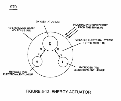
… allowing Atomic Energy Level Adjustment (540) of Figure (5-7) to take place, as illustrated in (970) of Figure (5-12) ... re-energizing the water molecule for hydrogen reuse, as illustrated in (530) of Figure (5-6).
How it is written
- (970) 14×
Drawings 6
-
(970) of Figure (5-12) · Solar Energy Actuator
-
Carries this number · Illustrations
-
The programmable pulse-frequency (49a xxx 49n) of Figure (10-1) input is simply adjusted to tune-in to the dielectric property of the Water Molecule. · Propagating Electrical Stress
-
Carries this number · WFC 429 - Illustrations
-
Carries this number · Wobbling Effect
-
(970) of Figure (10-1) · VIC Switchover Circuit
Where it is named · 14
Solar Energy Actuator 2×
-
… allowing Atomic Energy Level Adjustment (540) of Figure (5-7) to take place, as illustrated in (970) of Figure (5-12) ... re-energizing the water molecule for hydrogen reuse, as illustrated in (530) of Figure (5-6).
-
(970) of Figure (5-12)
Propagating Electrical Stress 5×
-
… Patent Law (35 USC 101) demonstrate operability, the applied Pulse-Voltage Frequency is adjusted to tune-in to the dielectric properties of water by the use of WFC "Amp Inhibiting Circuit" (970) of Figure (10-1), as further illustrated in WFC Tech-Brief titled "The Birth of New Technology"
-
Amp Inhibiting Circuit (970)
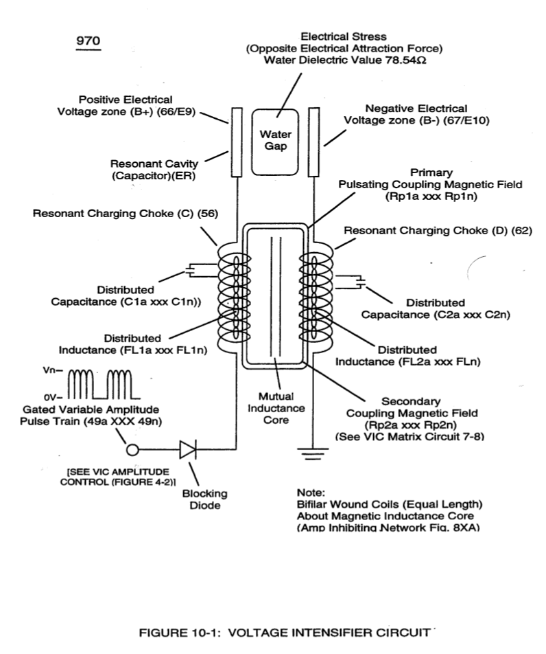
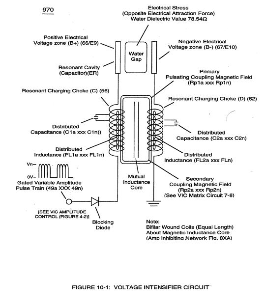
The Amp Inhibiting Circuit (970) of Figure (10-1) as to (690) of Figure (7-8) is composed of two copper wires "Bifilar" wound (wrapped) about a magnetic induction core to allow amp restriction (minimizing current leakage) while enco …
-
Amp Inhibiting Circuit (970)
Amp Inhibiting Circuit (970) of Figure (10-1)
-
Amp Inhibiting Circuit (970)
Beyond amp restricting characteristic of said Amp Inhibiting Circuit (970) of Figure (10-1) as to Voltage Intensifier Circuit (60) of Figure (3-22), the spiral-wrapped coils (Resonant Charging Chokes 56/62) being paired together, also, causes voltage level enhancement beyon …
-
Voltage Intensifier Circuit Diagram (970)
The resultant voltage enhancement (Voltage Amplitude) can exceed 40 kilovolts to instantly convert water (droplets) into thermal explosive energy (gtnt) on demand, as so illustrated in Voltage Intensifier Circuit Diagram (970) of Figure (10-1).
Voltage to Amp Differential Ratio 5×
-
The greater the Electrical Stress (RU-RU' a xxx ST -ST'n) applied (64B+/64B-a xxx 64B+/64B-), the greater amount of thermal explosive energy (16/gtnta xxx 16/gtntn) of Figure (6-2) as to (70) of Figure (4-5) is released from Resonant Water Gap (Cp) (970) of Figure (10-1), as further illustrated in (70) of Figure (4-5).
-
Voltage Intensifier Circuit (970)
keeping amp-surge (inhibiting amp flow) to a minimal level [See Voltage Performance Graph (750) of Figure (7-14)] while enhancing Voltage Potential of Electrical Stress (64/RU-RU'a xxx 64/ST-ST'n) as additional Dual Choke Coils (56/62 _ SS56/62) are included in the stacked coil-array forming Voltage Intensifier Circuit (970) of Figure (10-1) as to (620) of figure (7-1)
-
Voltage Intensifier Circuit (970)
Voltage Intensifier Circuit (970) of Figure (10-1)
-
Together, Coil Stages (56/62a xxx 56/62n + SS56/62a xxx SS56/62) added/stacked sequentially into a single overall coil-array assembly (990A/B) of Figure (10-3) forms Amp Inhibiting Network (Figure 8XA) as to (970) of Figure (10-1) (hereinafter called VIC Multi-Coil Spool Assembly).
-
Amp Inhibiting Circuit (970)
Amp Inhibiting Circuit (970) of Figure (10-1) restricts/inhibits amp flow to a minimal level while elevating "Difference of Potential" to the highest possible level.
VIC Switchover Circuit 2×
-
The simultaneous formation of both the positive voltage field (952) and the negative voltage field (953) is simply accomplished by the mutual electromagnetic inductance coupling field that is produced between the two bifilar wrapped coils (957/56 - 958/62) when the primary coil (957/56) is electrically energized by incoming voltage pulse train (T4a xxx T4n), as so illustrated in (970) of Figure (10-1).
-
(970) of Figure (10-1)