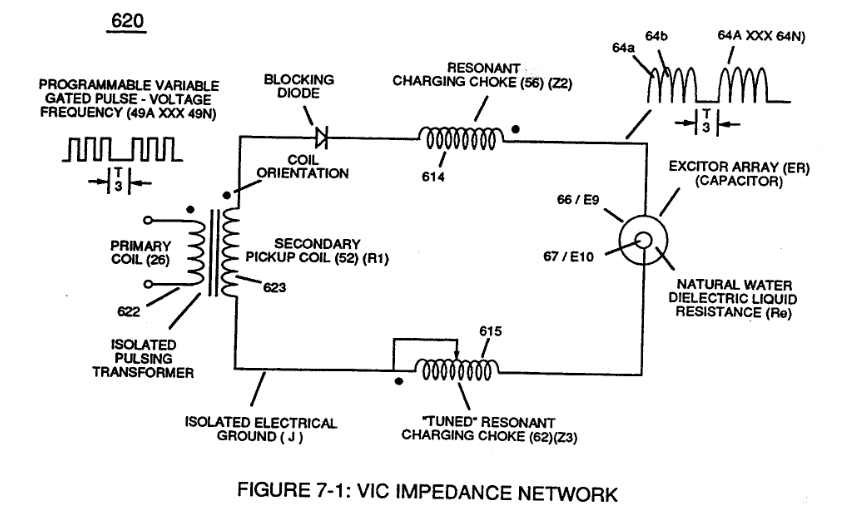
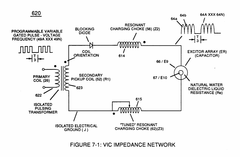
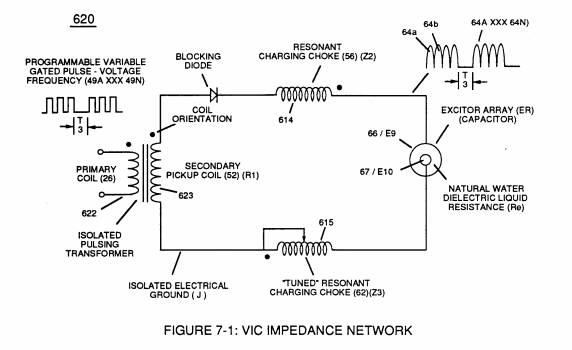
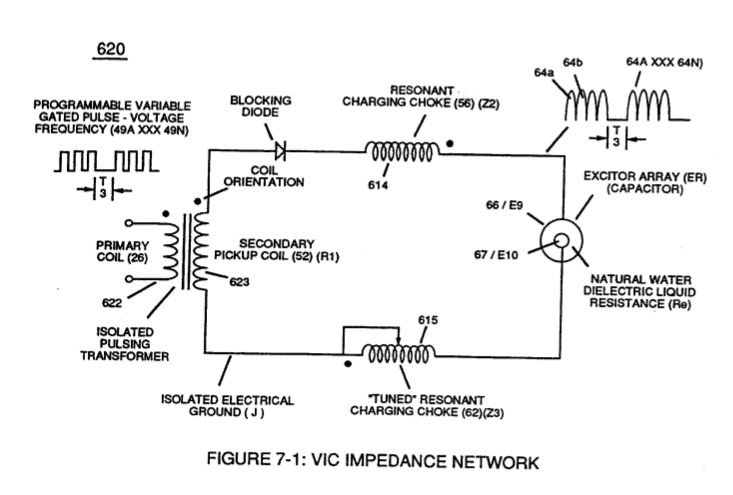
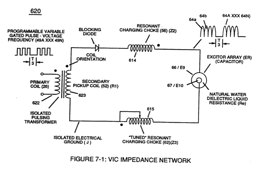
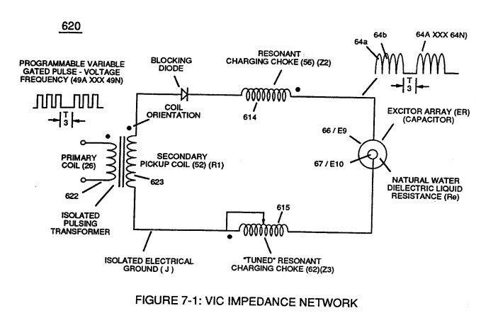
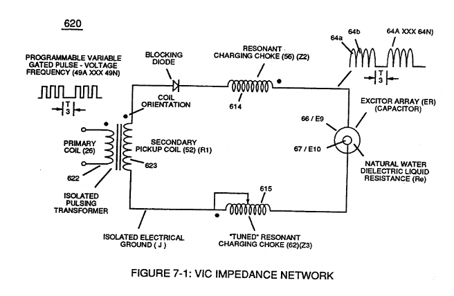
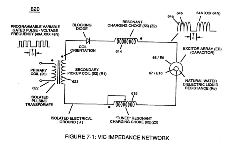
Figure (7-1)
VIC Impedance Network
How it is written
- (7-1) 42×
Drawings 13
-
Voltage Intensifier Circuit (620) of Figure (7-1) · Instant Explosion of Water
-
(620) of Figure (7-1) · Instant Explosion of Water
-
(620) of Figure (7-1) · Resistance (Rs)
-
(614) of Figure (7-1) · Inductance (FL)
-
Inductor (614) of Figure (7-1) · Inductance (FL)
-
(614) of (7-1) · Inductance (FL)
-
Figure (7-1) · Capacitance (Cd)
-
(620) of Figure (7-1) · Inductance Reactance (Rs - Cd - FL)
-
Choke-Coil (62) of Figure (7-1) · Transformer Action
-
Captioned as this figure · WFC 426 - Illustrations
-
(620) of Figure (7-1) · 8-6 - VIC Voltage Sync-Pulse Circuit
-
"Resonant Charging Choke" (56) of Figure (7-1) · Propagating Electrical Stress
-
(620) of figure (7-1) · Voltage to Amp Differential Ratio
On this figure 25
- 26 Primary Coil
- 35 Resonant Cavity Zone
- 49 Voltage Pulse frequency
- 52 Secondary Coil
- 56 Resonant Charging Choke
- 62 Resonant Charging Chokes
- 64 Pulse Train
- 66 Positive Voltage Potential
- 67 Opposite Polarity
- 71 Magnetic Field Coupling
- 85 Water Molecule
- 140 Resonant Capacitor
- 170 Resonant Cavity
- 614 Inductor
- 615 Resonant Charging Chokes
- 620 VIC Impedance Network Circuit
- E9 Capacitor
- E10 Capacitor
- ER Excitor-Array
- FL2 Distributed Inductance
- L2 Inductors
- T3 Unipolar Pulse-Train
- V Voltage Amplitude
- VIC Resonant Cavity Voltage Intensifier Circuit
- Vb VIC Voltage Enhancement Circuit
Where it is named · 42
Instant Explosion of Water 7×
-
Voltage Intensifier Circuit (60) of Figure (3-22) (Memo WFC 422 DA) as to Figure (1-1) (Memo WFC 420) and Voltage Intensifier Circuit (620) of Figure (7-1) are specifically designed to restrict amp flow during Programmable Pulsing Operations (49a xxx 49n) but in different operational modes:
-
Voltage Intensifier Circuit (620) of Figure (7-1)
-
VIC Voltage Enhancement Circuit (VIC - VB) (620) of Figure (7-1) incorporates the use of stainless steel wire-wrap coils (614/615) to accomplish the formation of unipolar gated pulse-wave (64a xxx T3 xxx 64n) without experiencing "signal distortion" or "signal deg …
-
(VIC - VB) (620) of Figure (7-1)
-
(620) of Figure (7-1)
Resistance (Rs) 2×
-
(620) of Figure (7-1)
Inductance (FL) 7×
-
(614) of Figure (7-1)
-
… pulsing transforms Inductor (614) of Figure (7-1) / Capacitor (E9/E10) of Figure (7-11) LC circuit of Figure (7-2) into an Resonant Charging Choke (614) which steps up an unipolar oscillation of an given charging frequency with the effective capacitance of a pulse-forming network (64a xxx 64n) of Figure (7-1) as to (600) of Figure (6-3) in order to charge Voltage Zones (E9/E10) to a higher potential beyond applied voltage input
-
Inductor (614) of Figure (7-1)
-
... interacting Distributed Capacitance (Cda xxx Cdn) and Distributed Inductance (D1a xxx D1n) of Figure (7-3) of Inductor Coil (614) of (7-1) with "Electrical Charging Effect" brought on by the dielectric value of water bath (85/Re), as pictorially illustrated in (650) of Figure (7-4).
-
(614) of (7-1)
Capacitance (Cd) 7×
-
Capacitor (E9/E10) of Figure (7-1) as to Figure (650) of Figure (7-4) in direct relationship to Water Gap (616) becomes Taper Resonant Cavity (720) of Figure (7-11) as shown in (590) of Figure (6-2) since Water Gap (616) is occupied by a dielectric liquid (Re) as herein before identified as natural water (85) having no electrolyte added thereto
-
Figure (7-1)
-
... a resistive liquid (having an ohmic value of 78.54 ohms) that takes on an "Electrical Charge" when applied voltage Potential (66/67) of Figure (7-1) as to (650) of Figure (7-4) causes and sets up Molecular Polarization Alignment (617) of Figure (7-4) by way of electrical molecular rotation (opposite electrical attraction force to rotate and position particle alignment) of each water Molecule (85a - 85b - 85c - 85n). …
-
(66/67) of Figure (7-1)
-
Inherently, then, Resonant Cavity (720) of Figure (7-11) as to (650) of Figure (7-4) forms capacitor (ER) of Figure (7-1) when the dielectric liquid of water (85) is placed or injected between electrical conducting plates (E9/E10) while applied voltage Potential of opposite polarity (66/67) is directly exposed to Water …
-
Figure (7-1)
-
Inductor (614) and Inductor (615) of Figure (7-1) as to (670) of Figure (7-6) is wound or coil-wrapped (see multi-layer equation Eq. 20) in such a manner as to increase the magnetic flux intensity (D1a xxx D1n) of Figure (7-3) as to (580) as to Figure (6-1) in reference to (710) of Figure (7-10) between the turns (618a xxx 618n) of coil-wrap (640).
Inductance Reactance (Rs - Cd - FL) 7×
-
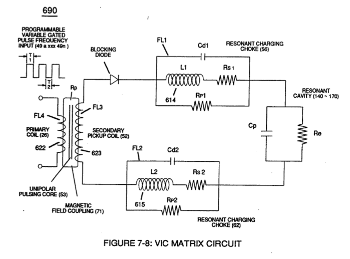
… Voltage Potential (626) of Figure (7-7) but, also, establishes "Impedance Field" (FL) across Inductors (L1-L2) of Figure (7-6) which acts and performs as Resonant Charging Chokes (614/615) of Figure (7-1) once placed on opposite side of capacitor (ER) forming Resonant voltage Effect Circuit (670) of Figure (7-6), as illustrated in (620) of Figure (7-1) as to (690) of Figure (7-8).
-
Resonant Charging Chokes (614/615) of Figure (7-1)
-
while, at the same time, Inductor Field (L2-FL2) restricts electron movement through VIC Impedance Network Circuit (620) of Figure (7-1) since Inductance Field (FL2) locks onto Electrons Magnetic Field (547) of Figure (5-9) to block the movement of electron flow toward Positive Voltage Potential (66)
-
(620) of Figure (7-1)
-
… further illustrated in electromagnetic coupling fields (71 - 511 - 512) of Figure (6-1) that encourages, brings-on, and perform Voltage Inducement Process (580) of Figure (6-1) as to (620) of Figure (7-1) without amp "influxing" (inhibiting amp flow) between Positive Voltage Potential (66) and Negative Voltage Potential (67) electrically applied across Resonant Cavities (140 -170).
-
(620) of Figure (7-1)
Transformer Action 3×
-
… 00) of Figure (7-9) to produce ''Negative Voltage Potential" ( B- ) at one side of Water Gap (Cp) of Figure (7-8) is accomplished by low electrical power input (Tab 38) when Choke-Coil (62) of Figure (7-1) magnetic field (FL2) (690) of Figure (7-8) during pulse on-time (49) impede "Electron-Flow" since electron mass is composed of electromagnetic matter which interacts with magnetic field strength (FL2 …
-
Choke-Coil (62) of Figure (7-1)
Mode of Operability 1×
-
Pulse Off-time (T2) of Figure (7-8) as to (620) of Figure (7-1) is adjusted to compensate for the rise and fall of magnetic coupling field (71) to produce applied Unipolar Wave-forms (64a xxx 64n) entering into Wave-guides (35a/35b/35c).
8-6 - VIC Voltage Sync-Pulse Circuit 2×
-
(620) of Figure (7-1)
Propagating Electrical Stress 3×
-
… w amp restriction (minimizing current leakage) while encouraging "Voltage Potential"(Va xxx Vn) across the water molecule to perform WFC "Electrical Polarization Process", as so illustrated in Figure (7-1) WFC memo (426) titled VIC Matrix Circuit.
-
The energized "Resonant Charging Choke" (56) of Figure (7-1) as to Figure (10-1) by way of input voltage-pulses (49a xxx 49n) creates an electromagnetic coupling field (Rp1) of Figure (7-8) due to its self-inductance (640) of Figure 7-3B) crosses over and passes through electrically ground connected Resonant Charging Choke (62), as so illustrated in Figure (10-1)
-
"Resonant Charging Choke" (56) of Figure (7-1)
Voltage to Amp Differential Ratio 2×
-
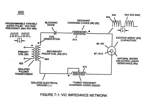
keeping amp-surge (inhibiting amp flow) to a minimal level [See Voltage Performance Graph (750) of Figure (7-14)] while enhancing Voltage Potential of Electrical Stress (64/RU-RU'a xxx 64/ST-ST'n) as additional Dual Choke Coils (56/62 _ SS56/62) are included in the stacked coil-array forming Voltage Intensifier Circuit (970) of Figure (10-1) as to (620) of figure (7-1)
-
(620) of figure (7-1)
Appendix B - Glossary of Applicaiton Notes 1×
-
… (700) of Figure (7-9) to produce "Negative Voltage Potential" (B-) at one side of Water Gap (Cp) of Figure (7-8) is accomplished by low electrical power input (Tab 38) when Choke-Coil (62) of Figure (7-1) magnetic field (FL2) (690) of Figure (7-8) during pulse on-time (49) impede "Electron-Flow" since electron mass is composed of electromagnetic matter which interacts with magnetic field strength (FL2). …