(16) · also written as a run, 16a xxx 16n
Flame Projection
Also written energy-flame · variable controlled pulse-shape · Thermal Explosive Energy-Yield · time-base unipolar pulse · thermal gas expansion · Resonant Pulse Waves · electrostatic force · repetitive manner and 3 more
Where it is first named
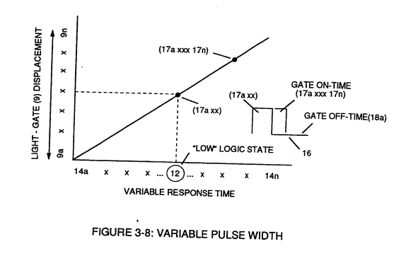
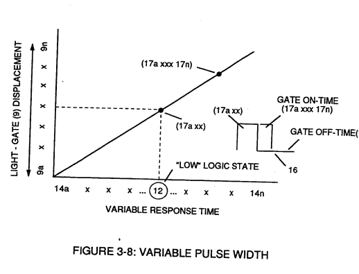
As signal output (15) of figure (4) (14a xxx ... 12 ... xx14n) is being received by acceleration control circuit (30) of Figure (3-5) as to Figure (3-12), circuit (30) converts incoming time-response signal (14a xxx ... 12 ... xx14n) into a variable time-base unipolar pulse (16), as shown in Figure (3-8).
How it is written
- (16) 24×
- (16a xxx 16n) 7×
- (14/16) 2× with (14) Response-Time
- (100 xxx 16n) 1×
- (16a xxx) 1×
- (16a xxx 16L = 16n) 1×
16a xxx 16n is Meyer's shorthand for a run of the same thing: 16a is the first, 16n the last, and the x's stand for however many lie between. Every stage of the run is this one numeral.
Drawings 100
-
Stanley A. Meyer Page_3 of 28 · WFC 417 — WFC 417
-
Carries this number · Figure 9B & 9BB - Applied Voltage To Plates
-
Figure (1-3) · LC Circuit
-
Figure (1-5) · LC Voltage
-
Ohm's Law for LED circuit in parallel array, and is given by (Eq 16) · Laser Interaction
-
Carries this number · WFC 420 - Illustrations
-
Carries this number · Acceleration Control Circuit (30)
-
Toggling action at full-scale deflection (13a xxx 13n) occurs in the range of (10) kHz or above and thus, allows instant response to driver's acceleration demands. · Acceleration Control Circuit (30)
-
Figure (3-13) · Acceleration Control Circuit (30)
-
Figure (3-13) · Acceleration Control Circuit (30)
-
Figure (3-16) · Acceleration Control Circuit (30)
-
Figure (3-16) · Variable Pulse Frequency Generator (70)
-
Ohm's law for led circuit in parallel array, and, is given by (Eq 16) · Gas Processor
-
Carries this number · Laser Distributor
-
Water Fuel Injector Plug (40) of Figure (4-2) · Operational Parameters
-
Carries this number · WFC 422DA - Illustrations
-
Carries this number · WFC 422DA - Illustrations
-
Carries this number · WFC 422DA - Illustrations
-
Carries this number · WFC 422DA - Illustrations
-
Carries this number · Water Fuel Injection System
-
3-16 Mount Bar · Voltage Intensifier Coil Assembly
-
Carries this number · Electronic Circuit Design
-
Carries this number · Electronic Circuit Design
-
Carries this number · Electronic Circuit Design
-
Carries this number · Electronic Circuit Design
-
Carries this number · Electronic Circuit Design
-
Carries this number · Electronic Circuit Design
-
Carries this number · Electronic Circuit Design
-
Carries this number · Electronic Circuit Design
-
Carries this number · Electronic Circuit Design
-
Carries this number · Electronic Circuit Design
-
Carries this number · Electronic Circuit Design
-
Water Fuel Injection System (10) of Figure (1) · Water Fuel Injector (Taper Resonant Cavity Chamber)
-
...positive charged gas particles (81a xxx 81n) being directed to and attached to negative charged oxygen atom (76) of water molecule (47); · Water Fuel Injector (Taper Resonant Cavity Chamber)
-
(70) of Figure (3B) · Water Fuel Injector (Taper Resonant Cavity Chamber)
-
Carries this number · Water Fuel Injector (Taper Resonant Cavity Chamber)
-
Electronic Circuit (110) of Figure (7) · Water Fuel Injector (Taper Resonant Cavity Chamber)
-
Carries this number · Water Fuel Injector (Taper Resonant Cavity Chamber)
-
Carries this number · Water Fuel Injector (Taper Resonant Cavity Chamber)
-
Carries this number · Funneling Effect
-
(520) of Figure (4-3) · Funneling Effect
-
thereby, attenuating voltage amplitude (voltage intensity) beyond Secondary Coil (53) voltage levels (71), as illustrated in (220) of Figure (18). · Funneling Effect
-
Figure 1-3 · Amp Inhibiting Circuit Vs Voltage Enhancement
-
2-2 Plug Housing · Water Fuel Injector Illustrations
-
Carries this number · Cover Page
-
Figure (3-6) · Water Fuel Injection System - Page 1
-
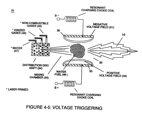
Figure (4-5) · Water Fuel Injection System - Page 1
-
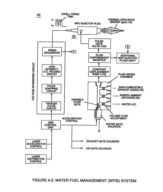
Figure (4-2) · Water Fuel Injection System - Page 1
-
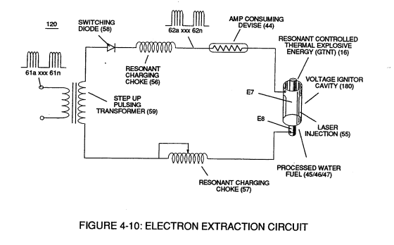
Figure (4-10) · Water Fuel Injection System - Page 2
-
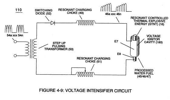
Figure (4-9) · Water Fuel Injection System - Page 2
-
Figure (4-7) · Water Fuel Injection System - Page 3
-
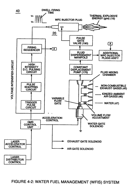
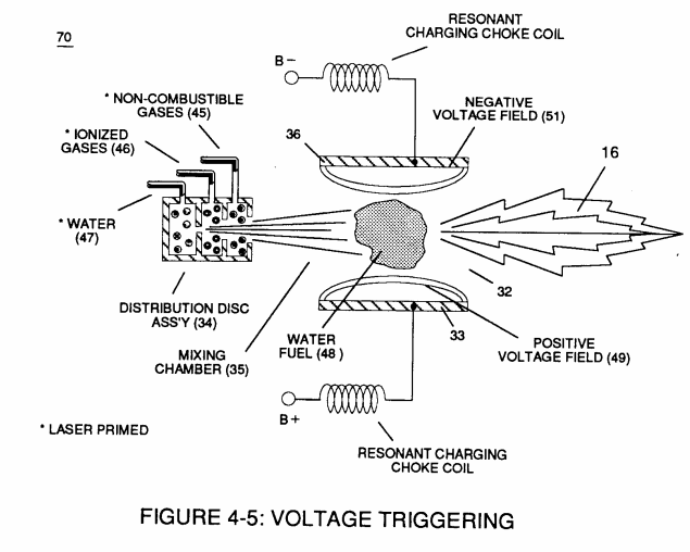
but, also prevents electron flow into destabilizing gas process (180), as so illustrated in Figure (4-5). · Water Fuel Injection System - Page 3
-
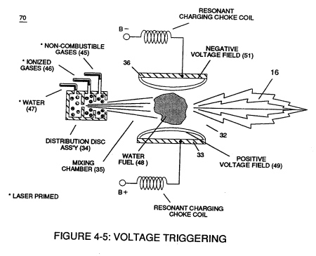
which simply uses Water Fuel Management (WFMS) System fluid-metering system (40) to control gas ignition (16), as illustrated in (40) of Figure (4-2). · Water Fuel Injection System - Page 4
-
Carries this number · Energy Pumping Action
-
(520) in Figure (5-3) · Resonant Propagation
-
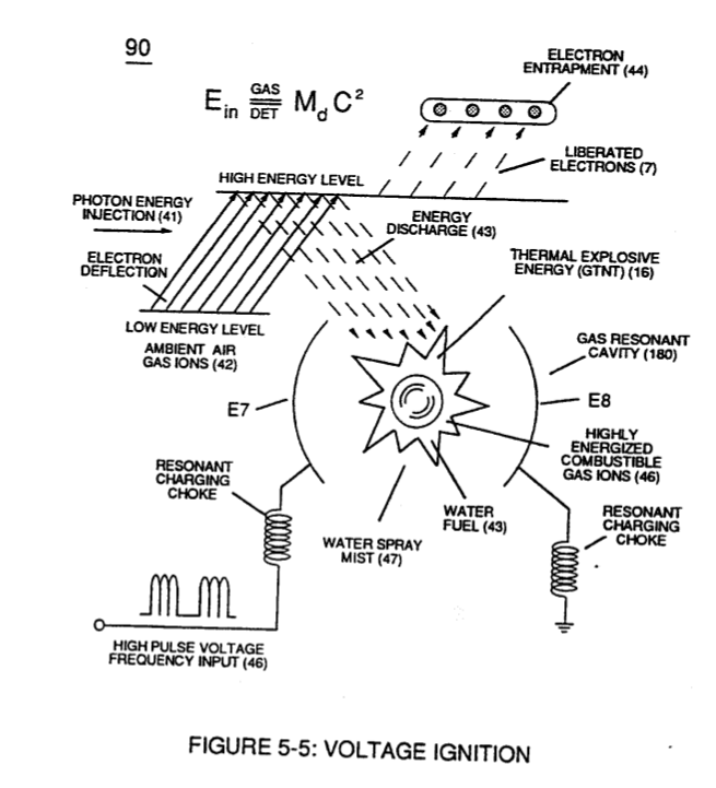
Figure (5-5) · Resonant Propagation
-
Carries this number · In Application of Usage
-
(520) of Figure (5-3) · In Application of Usage
-
(110) of Figure (4-9) · In Application of Usage
-
(57) of Figure (6-2) · In Application of Usage
-
(520) of Figure (5-3) · Solar Energy Actuator
-
Carries this number · Illustrations
-
Carries this number · Illustrations
-
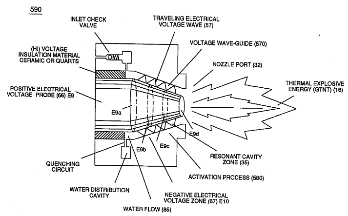
Activation Process (590) of Figure (6-2) · Voltage Intensifier Coil-Assembly
-
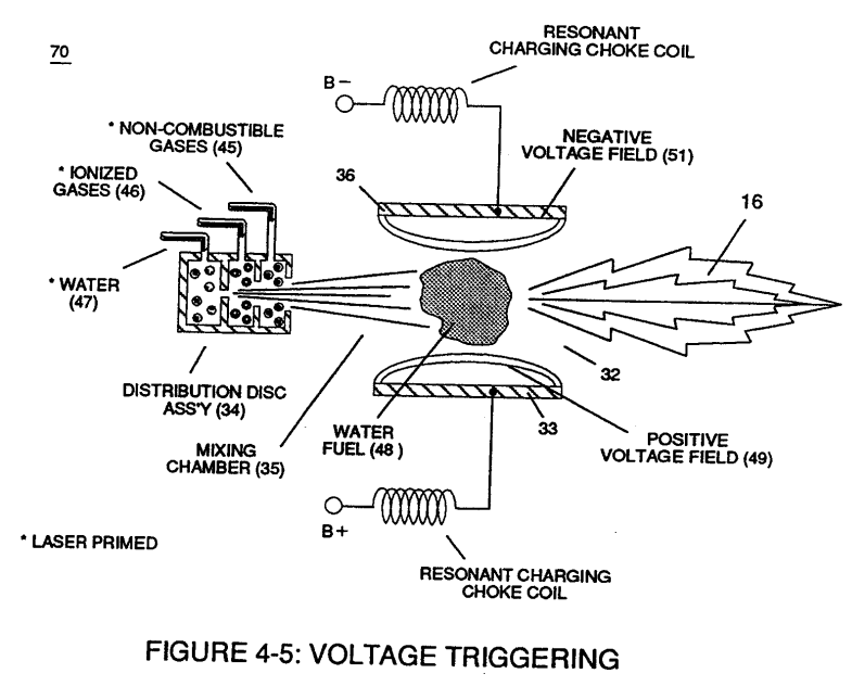
Voltage Triggering Process (70) of Figure (4-5) · Voltage Intensifier Coil-Assembly
-
Hydrogen Fracturing Process (520) of Figure (5-3) · Voltage Intensifier Coil-Assembly
-
(16) of Figure (4-5) · Resistance (Rs)
-
(110) of Figure (4-9) · Resistance (Rs)
-
(590) of Figure (6-2) · Capacitance (Cd)
-
(90) of Figure (5-5) · Capacitance Reactance
-
(90) of Figure (4-7) · Capacitance Reactance
-
Figure (4-5) · Capacitance Reactance
-
... causing "electron clustering" (641a xxx 641n) to take place within Copper Wire Zone (52) during pulse on- time (T1) · Electron Bounce Phenomenon
-
(E9/10) of Figure (6-2) · Voltage Amplitude Switch-Off
-
Carries this number · WFC 426 - Illustrations
-
(90) of Figure (5-5) · 8-2 - Traveling Voltage Wave-Guides
-
(520) of Figure (5-3) · 8-2 - Traveling Voltage Wave-Guides
-
Figure (4-5) · 8-5 - Energy Vectoring (Ev)
-
(40) of Figure (4-2) · 8-5 - Energy Vectoring (Ev)
-
Resonant Cavity (90) of Figure (4-7) · 8-5 - Energy Vectoring (Ev)
-
Energy Pumping Action (520) of Figure (5-3) · WFC Development Objectives
-
Voltage Intensifier Circuit (110) of Figure (4-9) · WFC Exhaust Air Reclaimer
-
Blocking Diode (52) of Figure (4-9) · Propagating Electrical Stress
-
Differential Voltage Wave-Guild (1040B) · Electrical Crossover Switching Circuit
-
When (B+/B+ - B-/B- / 1030B) switch function is activated, switch terminals (T1/T2 - T3/T4) are closed. · Electrical Crossover Switching Circuit
-
reciprocating WFC Fuel-kits can be similar to Car design (340); · Aviation Application
-
3-8 Multi-Coil Spool · Voltage Intensifier Coil Assembly
-
3-13 Flat Seal · Voltage Intensifier Coil Assembly
-
The figure it sits on · Electronic Circuit Design
-
(220) of Figure (18) · Water Fuel Injector (Taper Resonant Cavity Chamber)
-
The figure it sits on · Water Fuel Injector (Taper Resonant Cavity Chamber)
-
The Following Page 1-7 was not available · Water Fuel Injector (Taper Resonant Cavity Chamber)
-
Figure (4-1) · Water Fuel Injection System - Page 1
-
The figure it sits on · WFC 427 Illustrations
-
"FullSystem" development (10) of Figure (4-1) · WFC Development Objectives
-
Figure (10-3 A/B) · Propagating Electrical Stress
-
The figure it sits on · WFC 429 - Illustrations
-
The figure it sits on · WFC 429 - Illustrations
-
The figure it sits on · WFC 429 - Illustrations
-
The figure it sits on · Wobbling Effect
Where it is named · 36
Acceleration Control Circuit (30) 4×
-
time-base unipolar pulse (16)
As signal output (15) of figure (4) (14a xxx ... 12 ... xx14n) is being received by acceleration control circuit (30) of Figure (3-5) as to Figure (3-12), circuit (30) converts incoming time-response signal (14a xxx ... 12 ... xx14n) into a variable time-base unipolar pulse (16), as shown in Figure (3-8).
-
pulse shape (16)
Toggling-time (scanning-time) is directly synchronized to light gate (9) displacement which, in turns, circuit (30) further sets up and establishes a given pulse shape (16) of Figure (3-8).
-
variable controlled pulse-shape (16)
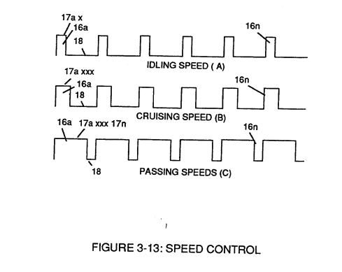
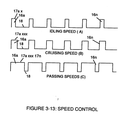
Finally, circuit (30) reproduces the variable controlled pulse-shape (16) in a continuous repetitive manner (16a xxx 16n) of Figure (3-13) and electrically transmits the resultant pulse-train signal (19) to Analog Voltage Circuit (40), as shown in Figure (3-5).
-
repetitive manner (16a xxx 16n)
Finally, circuit (30) reproduces the variable controlled pulse-shape (16) in a continuous repetitive manner (16a xxx 16n) of Figure (3-13) and electrically transmits the resultant pulse-train signal (19) to Analog Voltage Circuit (40), as shown in Figure (3-5).
Analog Voltage generator (40) 1×
-
pulse train (100 xxx 16n)
The newly formed analog signal (22) of Figure (3-14) is a voltage level signal that varies continuously in both time and amplitude to produce a voltage level which is directly proportional to the physical change in pulse train (100 xxx 16n) of Figure (3-13).
Water Fuel Injection System 7×
-
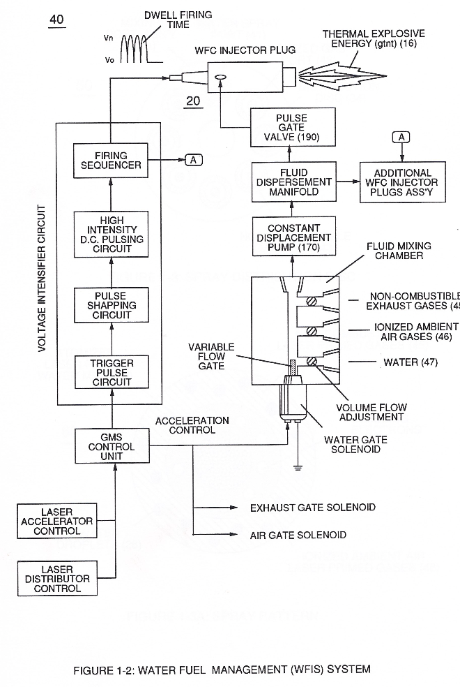
Operationally, Water Fuel injector assembly (10) of Figure (1) as to (40) of Figure (2B) performs several functions simultaneously to produce thermal explosive energy-yield (gtnt) (16) on demand:
-
… gen Fracturing Process (390) of Figure (41) as to Figure (6) under control state (on demand) via electrical-static spark ignition (49 / 51) of Figure (3B)....releasing thermal explosive energy (gtnt) (16) passing beyond gas exit port (32) of Figure (3B), as further illustrated in Figure (2) as to Figure (1).
-
Voltage Igniter Stage (180) of Figure (3B) as to Voltage Intensifier Circuit (110) Figure (7) as to Extraction Circuit (120) of Figure (8) performs several functions simultaneously to initiate and trigger thermal explosive energy-yield (gtnt) (16) beyond normal gas burning levels:
-
… 420) to cause the resultant highly energized and mass destabilized combustible gas atoms (93a xxx 93n) of Figure (8) to perform Hydrogen Fracturing Process (80) of Figure (7) when electrostatic force (14/16) thermally ignites (kinetic agitation) destabilized water-fuel mixture (93a xxx 93n) under gas compression... …
-
Additional WFC Injector Assemblies (20) of Figure (2) are arranged in cluster array (20a xxx 20n) to increase energy-yield output (16a xxx 16n) of Figure (10 / 1 / 12).
-
… systems (Figure 10), rockets engines (Figure 12), or even car spark plugs (130) of Figure (9) which simply uses Water Fuel management (WFMS) system fluid-metering system (40) to control gas ignition (16), as illustrated in (40) of Figure (2B).
-
energy-flame (16)
Sequential pulsing of Water Fuel Injector (20/30) of Figure (1) as to (40) of Figure (2B) is system activated by Pulse Gate Valve (190) of Figure (1) to further control a predetermined energy-flame (16).
Water Fuel Injector (Taper Resonant Cavity Chamber) 5×
-
flame projection (16)
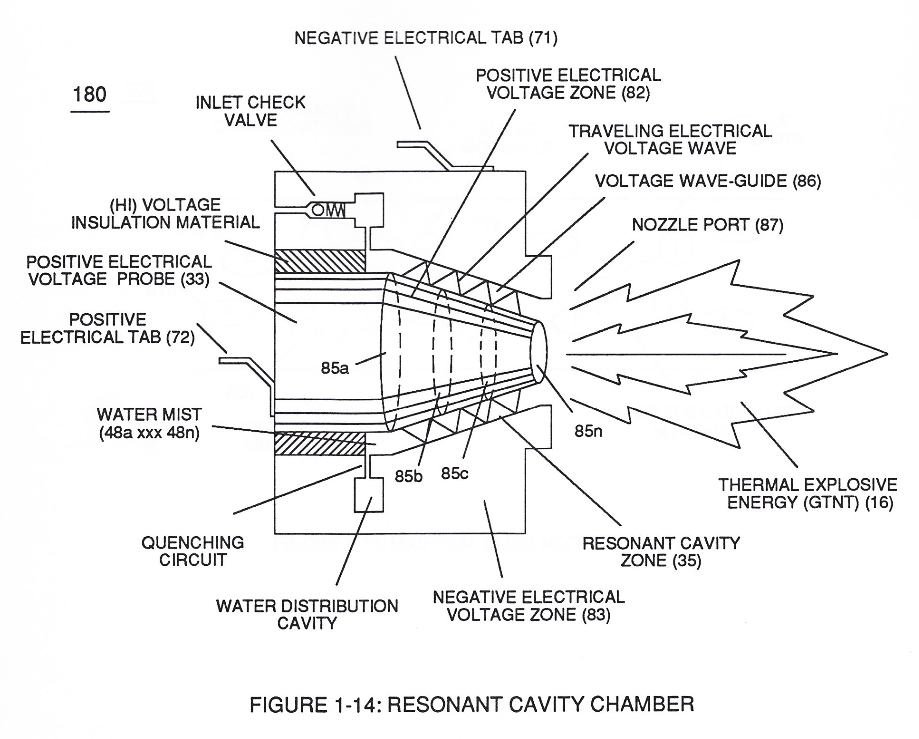
releasing thermal explosive energy (gtnt) via flame projection (16) of Figure (3B) as to Figure (14), Water Fuel Injection System (10) of Figure (1) as to (170) of Figure (13) incorporates and uses Taper Resonant Cavity Chamber (180) of Figure (14) to enhance operati …
-
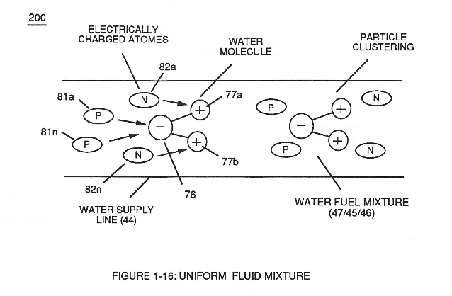
while, during the same interim period of time, negative charged gas particles (82a xxx 82n) being directed onward to and affix themselves to positive charged hydrogen atoms (77a / 77b), as illustrated in (200) of Figure (16).
-
Once water fuel-droplets (xxx 48n) fully occupies open space cavity (Resonant Cavity Zone) (35) and then exposed to applied pulsating opposite electrical voltage fields (49/51) of voltage wave form (280) of Figure (17), the electrically stimulated water fuel droplets (48a xxx 48n) are subjected to release thermal explosive energy (gtnt) (16) undergoing Electrical-Resonant in a sequential manner:
-
Thermal Explosive Energy release (16a xxx 16n) of Figure (14)
Funneling Effect 4×
-
thermal gas expansion (16)
At termination point (85), voltage intensity (VL x Va x Vb x Vc x Vn) is, now, increased to the point to cause Gas Ignition as Combustible Gas Atoms (76, 77a - 77b) which are, then, expelled from Gas Nozzle Port (87) of Figure (14) under dynamic pressure to allow thermal gas expansion (16) ... releasing thermal explosive energy (gtnt) beyond and away from Resonant Cavity Chamber (180), as illustrated in Figure (14).
-
To increase energy levels (16a xxx 16L = 16n) of Hydrogen Fracturing Process (100) as to (390), even further, simply switch-on additional Booster Coils (61a x 61L - 61n) in sequential order to increase voltage intensity (VL ~ Vn ~ Vm) to higher …
-
The established "Power Boost" energy level (16a xxx 16n) is changeable, however, by, simply, electrically moving or displacing (back and forth movement) Core-Slug (73) to another stop-location (72)... adjusting energy-level (16a xxx) on demand.
-
The established "Power Boost" energy level (16a xxx 16n) is changeable, however, by, simply, electrically moving or displacing (back and forth movement) Core-Slug (73) to another stop-location (72)... adjusting energy-level (16a xxx) on demand.
Water Fuel Injection System - Page 1 2×
-
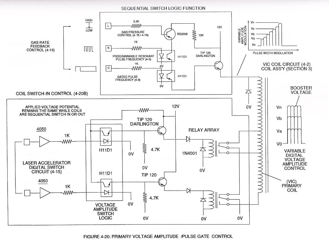
Operationally, Water Fuel injector assembly (10) of Figure (4-1) as to (40) of Figure (4-2) performs several function simultaneously to produce thermal explosive energy-yield (gtnt) (16) on demand:
-
.... releasing thermal explosive energy (gtnt) (16) passing beyond gas exit port (32) of Figure (4-5), as further illustrated in Figure (4-2) as to Figure (4-1).
Water Fuel Injection System - Page 2 1×
-
Voltage Igniter Stage (180) of Figure (4-5) as to Voltage Intensifier Circuit (110) Figure (4-9) as to Extraction Circuit (10) of Figure (4-10) performs several functions simultaneously to initiate and trigger thermal explosive energy-yield (gtnt) (16) beyond normal gas burning levels:
Water Fuel Injection System - Page 3 2×
-
electrostatic force (14/16)
… to cause the resultant highly energized and mass destabilized combustible gas atoms (93a xxx 93n) of Figure (4-10) to perform Hydrogen Fracturing Process (80) of Figure (4-9) when electrostatic force (14/16) thermally ignites (kinetic agitation) destabilized water-fuel mixture (93a xxx 93n) under gas compression
-
Additional WFC Injector Assemblies (20) of Figure (4-1) are arranged in cluster array (20a xxx 2On) to increase energy-yield output (16a xxx 16n) of Figure (4-12/4-13/4-14).
Water Fuel Injection System - Page 4 2×
-
gas ignition (16)
which simply uses Water Fuel Management (WFMS) System fluid-metering system (40) to control gas ignition (16), as illustrated in (40) of Figure (4-2).
-
energy-flame (16)
Sequential pulsing of Water Fuel Injector (20/30) of Figure (4-1) as to (40) of Figure (4-2) is system activated by Pulse Gate Valve (190) of Figure (4-1) to further control a predetermined energy-flame (16).
Taper Water Fuel Injectors 1×
-
... producing thermal explosive energy-yield (16), as further illustrated in (70) of Figure (4-5) titled "Voltage Triggering".
Resistance (Rs) 2×
-
... releasing thermal explosive energy (gtnt) (16) of Figure (4-5) on demand from natural water (85) of Figure (3-26) since the dielectric value (Re) of (Eq.9) of Water Fuel (85) is further approximated in Capacitance Equation (Eq.22), as illustrated in (650) of Figure (7-4) as to Tapered Voltage Wave-Guide (720) of Figure (7-11)
-
(16) of Figure (4-5)
In-Line Circuit Components 1×
-
Thermal Explosive Energy-Yield (gtnt) (16a xxx 16n) instantly produced from water (85) is determined by:
Capacitance Reactance 2×
-
Thermal Explosive Energy-Yield (16a xxx 16n)
Capacitor (ER) should remain relatively small due to the dielectric value of water to obtain maximum Thermal Explosive Energy-Yield (16a xxx 16n) of Figure (4-5) and subsequently establishing Quenching Circuit (370) of Figure (3-40) to prevent gas ignition inside traveling voltage wave-guide (590) of Figure (6-2) as to (730) of Figure (7-12)
-
... releasing thermal explosive energy (gtnt) (16) under control state.
Electron Bounce Phenomenon 1×
-
... triggering Hydrogen Fracturing Process (90) of Figure (5-5) as to (100) of Figure (4-8) ... instantly releasing thermal explosive energy (gtnt) (16) from Water (85) on demand, as illustrated in Taper Resonant Cavity (590) of Figure (6-2) as to (70) of Figure (4-5).
8-7 - Application of Usage 1×
-
Resonant Pulse Waves (16)
In each and all Flame-Front (582 A,B,C) Resonant Pulse Waves are produced to net higher energy-yield beyond normal gas burning levels. Laser Energy (588) being injected into Resonant Pulse Waves (16) by way of Laser Inject Tube-Port (589) helps maintain Plasma-temperatures at extremely elevated temperatures over the prior art.