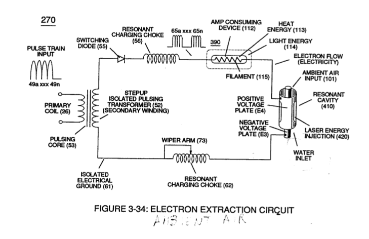
Figure (3-34)
Electron Extraction Cirquit
Also written Electron Extraction Circuit
How it is written
- (3-34) 17×
Drawings 5
-
(270) of Figure (3-34) · Gas Processor
-
Captioned as this figure · WFC 422DA - Illustrations
-
(270) of (3-34) · In Application of Usage
-
Figure (3-34) · Propagating Electrical Stress
-
blocking diode (55) of Figure (3-34) · Voltage to Amp Differential Ratio
On this figure 20
- 49 Voltage Pulse frequency
- 55 Switching Diode
- 56 Resonant Charging Choke
- 60 Voltage Intensifier Circuit
- 62 Resonant Charging Chokes
- 101 Ambient Air Gases
- 113 —
- 114 —
- 115 Light Bulb Filament
- 117 Liberated Electrons
- 260 Ionized Gas Process
- 270 Electron Extraction Circuit
- 390 Hydrogen Fracturing Process
- 410 Gas Resonant Cavity
- Cp Water Gap
- E3 Positive Electrical Voltage Field
- E4 Negative Electrical Voltage Fields
- Rp1 Coupling Inductance
- Rp2 Mutual Inductance Fields
- SS56 Resonant Charging Chokes Stages
Where it is named · 17
Gas Processor 11×
-
The resultant ionized gas process (260) of Figure (3-33) is performed by Electron Extraction Circuit (270) of Figure (3-34) which function in like manner to Voltage Intensifier Circuit (60) of Figure (3-22) except amp consuming device (390) (such as a light bulb 11_2) placed between Resonant Charging Choke (56) and Gas Re …
-
… to Voltage Intensifier Circuit (60) of Figure (3-22) except amp consuming device (390) (such as a light bulb 11_2) placed between Resonant Charging Choke (56) and Gas Resonant Cavity (410) of Figure (3-34) is added to pulsing circuit (60) to cause and convert liberated electrons (117a xxx 117n) into radiant heat - energy (Kinetic energy) (113) in the form of light energy (114)
-
Electron Extraction Circuit (270) of Figure (3-34)
-
Repetitive formation of electrical voltage force or voltage intensity (65a xxx 65n) of Figure (3-21) attracts and causes liberated electrons (117a,xxx 117n) to move electrically away from gas resonant cavity (410) and physically interact with light bulb filament (115) to initiate and perform kinetic conversion process (390), as further illustrated in (270) of Figure (3-34).
-
Pulsating voltage potential or voltage intensity (65a xx 65n) is adjusted, also, to "tune-in" to the resonant properties of ambient air gases (101) since ambient air gases (101) exhibits a dielectric value (air-gap of one inch resisting electron arc-over of up to 17,000 volts applied) between voltage plates (E3) and (E4), forming capacitor (410) of Figure (3-34).
-
Voltage fields (106/107) are physically configured (skin effect) by T304 stainless steel material to form voltage plates (E3/E4) of Figure (3-33) which are not only chemically inert to gas ionization process (260) but, also, forms tubular Gas Resonant Cavity (410) of Figure (3-34) having approximately the same size and shape of liquid resonant cavity (170) of Figure (3-25), as illustrated in (270) of Figure (3-34).
-
Voltage fields (106/107) are physically configured (skin effect) by T304 stainless steel material to form voltage plates (E3/E4) of Figure (3-33) which are not only chemically inert to gas ionization process (260) but, also, forms tubular Gas Resonant Cavity (410) of Figure (3-34) having approximately the same size and shape of liquid resonant cavity (170) of Figure (3-25), as illustrated in (270) of Figure (3-34).
-
(270) of Figure (3-34).
-
To further destabilize gas atom (104), emitted laser energy (electromagnetic energy having zero mass) (116) is, now, injected into Gas Resonant Cavity (410) via optical lens (121) and superimposed onto gas ionized process (260) and subsequently absorbed by gas atom nucleus (108), as illustrated in (260) of Figure (3-33) as to (270) of Figure (3-34).
-
(270) of Figure (3-34)
In Application of Usage 2×
-
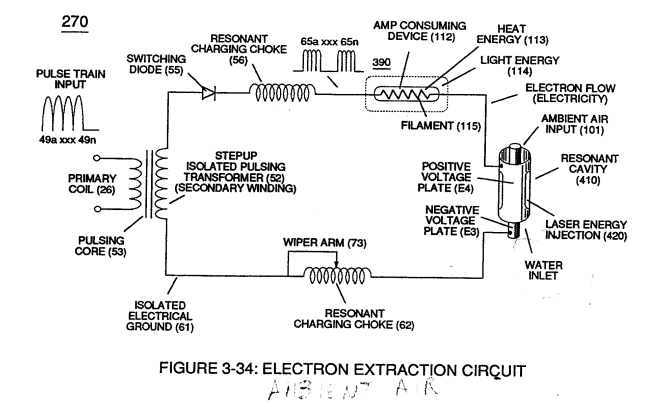
(270) of (3-34)
Propagating Electrical Stress 2×
-
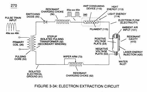
… ng magnetic field-strength during each pulsing cycle) of electromagnetic field-strength (Rp1a xxx Rp1n - Rp2a xxx Rp2n) (mutual induction) when applied Pulse-Voltage frequency (49a xxx 49n) of Figure (3-34) passes through the positive energized Resonant Charging Choke (56).
-
Figure (3-34)
Voltage to Amp Differential Ratio 2×
-
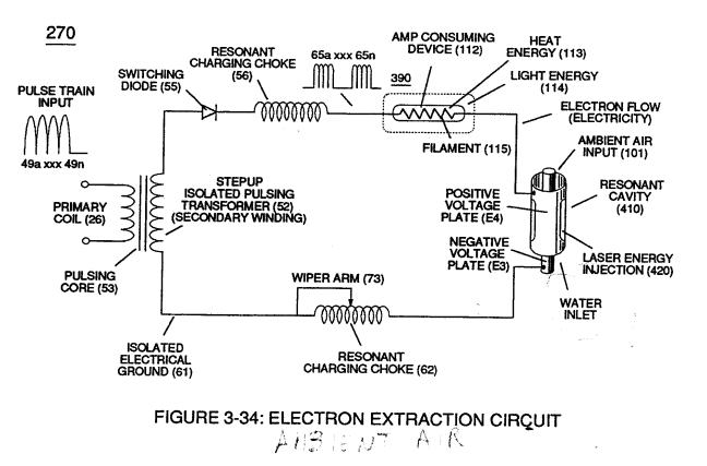
... allowing each/both bifilar coil assembly (56/62a xxx 56/62n -S- SS56/62a xxx SS56/62n) to be electrically and magnetically energized in the same progressive direction toward Water Gap (Cp) and away from blocking diode (55) of Figure (3-34) as to Figure (10-1) and Figure (10-3)
-
blocking diode (55) of Figure (3-34)