Figure (3-22)
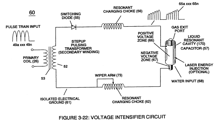
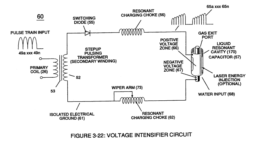
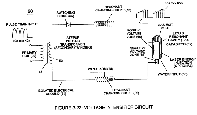
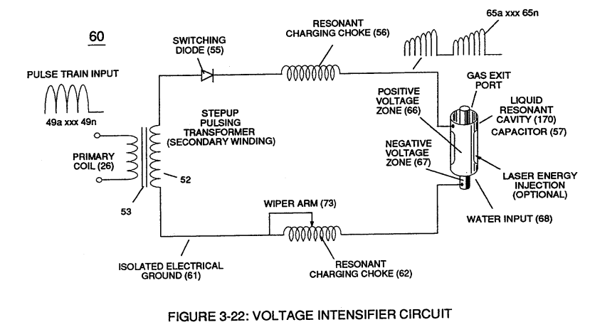
Voltage Intensifier Circuit
How it is written
- (3-22) 42×
Drawings 11
-
Figure (3-22) · Analog Voltage generator (40)
-
Figure (3-22) · Voltage Amplitude Control Circuit (50)
-
Figure (3-22) · Voltage Intensifier Circuit (60)
-
Figure (3-22) · Voltage Dynamics
-
Voltage Intensifier Circuit (60) of Figure (3-22) · Gas Processor
-
Captioned as this figure · WFC 422DA - Illustrations
-
Voltage Intensifier Circuit (60) of Figure (3-22) · Instant Explosion of Water
-
(56/62) of Figure (3-22) · Instant Explosion of Water
-
(56) of Figure (3-22) · Instant Explosion of Water
-
Voltage Intensifier Circuit (60) of Figure (3-22) · Propagating Electrical Stress
-
(60) of Figure (3-22) · Propagating Electrical Stress
On this figure 20
- 22 Compounding Action
- 26 Primary Coil
- 48 Water-fuel mixture
- 52 Secondary Coil
- 55 Switching Diode
- 56 Resonant Charging Choke
- 60 Voltage Intensifier Circuit
- 61 Negative electrical voltage potential
- 62 Resonant Charging Chokes
- 64 Pulse Train
- 65 Voltage Potential
- 66 Positive Voltage Potential
- 67 Opposite Polarity
- 68 Water Bath
- 73 Core-Slug
- 120 Fuel Cell
- 170 Resonant Cavity
- FL Optimize The Electromagnetic Field Strength
- Ll Coil-Wrap
- T2 Duty Cycle of Pulse Train
Where it is named · 42
Analog Voltage generator (40) 3×
-
Voltage valves or levels (22a xxx 22n) simply controls the applied voltage potential across Resonant Cavity Assembly (120) of Figure (3-22) through voltage amplitude control circuit (50) of Figure (3-5) which is is electrically linked to primary coil (26) of Figure (3-22) of Voltage Intensifier Circuit (60) of Figure (3-5).
-
Voltage valves or levels (22a xxx 22n) simply controls the applied voltage potential across Resonant Cavity Assembly (120) of Figure (3-22) through voltage amplitude control circuit (50) of Figure (3-5) which is is electrically linked to primary coil (26) of Figure (3-22) of Voltage Intensifier Circuit (60) of Figure (3-5).
-
Figure (3-22)
Voltage Amplitude Control Circuit (50) 2×
-
Figure (3-22)
Voltage Intensifier Circuit (60) 20×
-
By integrating and joining together variable voltage amplitude control signal (318 xxx 32n) of Figure (3-15) with variable controlled switch-gate (49a xxx 49n) of Figure (3-18) across primary coil (26) of Figure (3-22),
-
variable amplitude pulse-train (51a xxx 51n) of Figure (3-19) is electromagnetically coupled (transformer action) to secondary coil (52) of Figure (3-22) by way of pulsing core (53) of Figure (3-23) as to Figure (3-22).
-
variable amplitude pulse-train (51a xxx 51n) of Figure (3-19) is electromagnetically coupled (transformer action) to secondary coil (52) of Figure (3-22) by way of pulsing core (53) of Figure (3-23) as to Figure (3-22).
-
Figure (3-22)
-
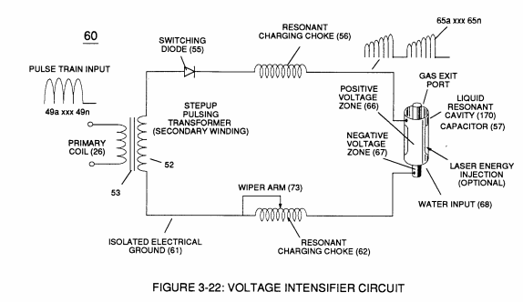
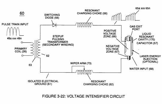
The resultant signal coupling ( 65a xx 65n ) of Figure (3-21) is accomplished since primary coil (26), pulsing core (53), secondary coil (52), switching diode (55), resonant charging choke (56), resonant cavity assembly (170), natural water (68), and variable resonant charging choke (62) forms Voltage Intensifier Circuit (60) of Figure (3-22), as illustrated in Figure (3-22) as to Figure (3-23).
-
The resultant signal coupling ( 65a xx 65n ) of Figure (3-21) is accomplished since primary coil (26), pulsing core (53), secondary coil (52), switching diode (55), resonant charging choke (56), resonant cavity assembly (170), natural water (68), and variable resonant charging choke (62) forms Voltage Intensifier Circuit (60) of Figure (3-22), as illustrated in Figure (3-22) as to Figure (3-23).
-
Figure (3-22)
-
Pulsing transformer (26/52) of Figure (3-22) steps up voltage amplitude or voltage potential (Vo xxx Vn) of Figure (3-19) during pulsing operations.
-
Movable wiper arm (73) of Figure (3-22) fine "tunes" "resonant action" during pulsing operations.
-
Inherently, then, pulsing core (53) of Figure (3-23) aids amp restriction while voltage intensifier circuit (190) is being "tuned" (adjusting pulse train 49a xxx 49n pulse-frequency 63 via pulse frequency generator 70 of figure 3-5) to match the resonant frequency properties of water bath (68) of Figure (3-22), as illustrated in Fuel Cell (120) of Figure (3-24).
-
Figure (3-22)
-
Figure (3-22)
Voltage Dynamics 2×
-
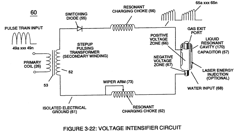
The higher the voltage potential (Vo xxx Vn), the greater "electrical attraction force" (qq') or "electrical repelling force" (ww') of Figure (3-29) is applied to electrical circuit (60) of Figure (3-22).
-
Figure (3-22)
Gas Processor 2×
-
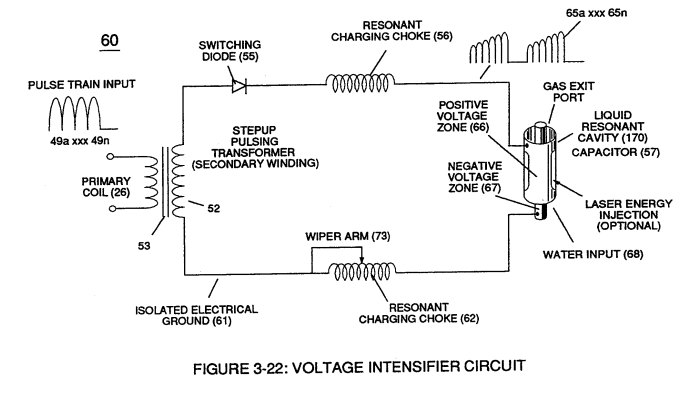
The resultant ionized gas process (260) of Figure (3-33) is performed by Electron Extraction Circuit (270) of Figure (3-34) which function in like manner to Voltage Intensifier Circuit (60) of Figure (3-22) except amp consuming device (390) (such as a light bulb 11_2) placed between Resonant Charging Choke (56) and Gas Resonant Cavity (410) of Figure (3-34) is added to pulsing circuit (60) to cause and …
-
Voltage Intensifier Circuit (60) of Figure (3-22)
Water Fuel Injector 1×
-
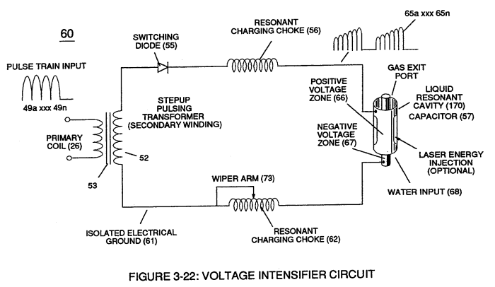
… imply electrically interfacing voltage intensifier (VIC) circuit coil-assembly (580) of Figure (6-1) with 'Taper Resonant Cavity" (590) of Figure (6-2), as schematically illustrated in (60) of Figure (3-22) as to pulse core configuration (190) of Figure (3-23) (Memo WFC 422 DA) titled "WFC Hydrogen Gas Management System.
Instant Explosion of Water 8×
-
Voltage Intensifier Circuit (60) of Figure (3-22) (Memo WFC 422 DA) as to Figure (1-1) (Memo WFC 420) and Voltage Intensifier Circuit (620) of Figure (7-1) are specifically designed to restrict amp flow during Programmable Pulsing Operations (49a xxx 49n) but in different operational modes:
-
Voltage Intensifier Circuit (60) of Figure (3-22)
-
VIC voltage circuit (60) utilizes copper wire-wrap to form Resonant Charging Chokes (56/62) of Figure (3-22) in conjunction with Switching Diode (55) to encourage and make use of "Electron Bounce" phenomena (700) of Figure (7-9) to help promote Step Charging Effect (628) of Figure (7-7) by preventing electr …
-
(56/62) of Figure (3-22)
-
Switching Diode (55) of Figure (3-22) prevents Bidirectional electron flow (current flow in one direction only) since Blocking Diode (55) only conducts "current flow" in the direction of schematic-arrow while being placed in-line with VIC Circuit impedance interaction (R1 + Z2 + Z3 + Re), as mathematically extrapolated in Circuit Equation (Eq 9)
-
(55) of Figure (3-22)
-
(56) of Figure (3-22)
Propagating Electrical Stress 4×
-
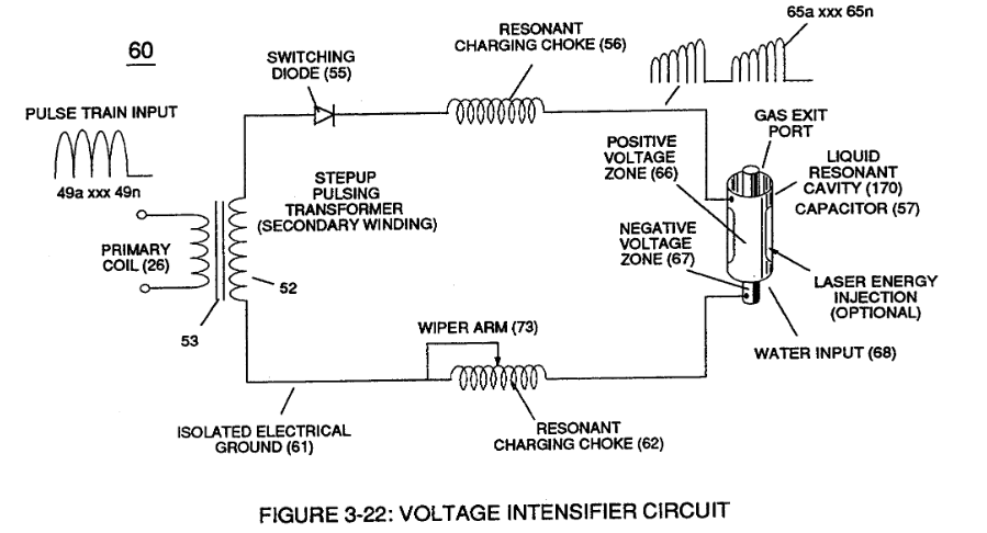
Beyond amp restricting characteristic of said Amp Inhibiting Circuit (970) of Figure (10-1) as to Voltage Intensifier Circuit (60) of Figure (3-22), the spiral-wrapped coils (Resonant Charging Chokes 56/62) being paired together, also, causes voltage level enhancement beyond applied voltage input since the "Distributed Capacitance" (C1a xxx C1n …
-
Voltage Intensifier Circuit (60) of Figure (3-22)
-
(60) of Figure (3-22)