(750)
Performance Graph
Also written Voltage Graph · Amp Inhibiting Process
Where it is first named
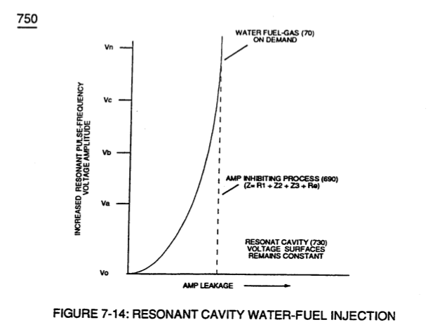
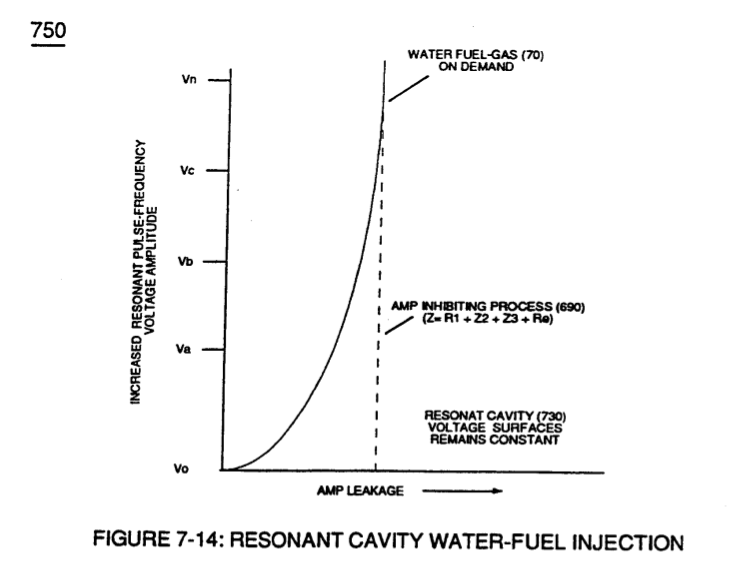
… otential" (600) of Figure (6-3) can perform work to trigger Hydrogen Fracturing Process (520) of Figure (5-3) (Memo WFC 424 DA) as to (100) of Figure (4-8) (Memo WFC 423DA), as graphically denoted in (750) of Figure (7-14) of WFC memo (426) titled VIC Matrix Circuit - Instant Explosion of Water.
How it is written
- (750) 13×
Drawings 12
-
3-4 Inner Core Bobbin · Voltage Intensifier Coil Assembly
-
3-6 Pulsing Core · Voltage Intensifier Coil Assembly
-
3-15 VIC Mount Plate · Voltage Intensifier Coil Assembly
-
Carries this number · Differential Air-Gas Inlet Control
-
Carries this number · Differential Air-Gas Inlet Control
-
2-5 Clamp Nut Assembly · Water Fuel Injector Illustrations
-
(750) of Figure (7-14) · Inductance (FL)
-
(750) of Figure (7-14) · Capacitance (Cd)
-
(750) of Figure (7-14) · Inductance Reactance (Rs - Cd - FL)
-
Voltage Graph (750) of Figure (7-14) · Electron Bounce Phenomenon
-
Carries this number · WFC 426 - Illustrations
-
Voltage Performance Graph (750) of Figure (7-14) · Voltage to Amp Differential Ratio
Where it is named · 13
Voltage Intensifier Coil-Assembly 1×
-
… otential" (600) of Figure (6-3) can perform work to trigger Hydrogen Fracturing Process (520) of Figure (5-3) (Memo WFC 424 DA) as to (100) of Figure (4-8) (Memo WFC 423DA), as graphically denoted in (750) of Figure (7-14) of WFC memo (426) titled VIC Matrix Circuit - Instant Explosion of Water.
Inductance (FL) 2×
-
(750) of Figure (7-14)
-
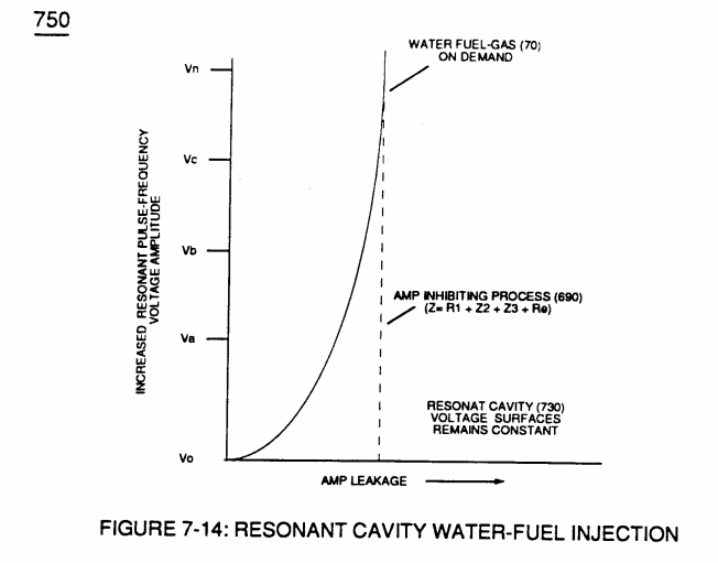
... distilled water, of course, is generally lab-tested 1ppm or less, as illustrated in (760) of Figure (7-15) as to (750) of Figure (7-14).
Capacitance (Cd) 2×
-
... generally rain water (85f) (750) of Figure (7-14) being almost free of contaminates due to Water Evaporation Process (532) of Figure (5-6) ... rain water (850 being an liquid-insulator that restricts the flow of amps
-
(750) of Figure (7-14)
Inductance Reactance (Rs - Cd - FL) 3×
-
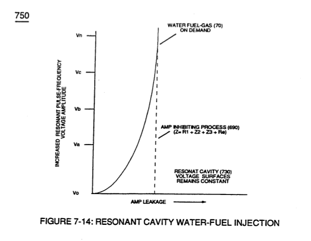
… flow to be reduce to a minimum value while allowing voltage potential (627) of Figure (7-7) to go toward infinity if the electronic components would allow it to happen, as graphically illustrated in (750) of Figure (7-14).
-
... thereby preventing and inhibiting electron-flow to pass through or arc-over capacitor water-gap (Cp) of Figure (7-8) such electron blocking action is herein called "Electron Inhibiting Effect" (631), as denoted in (670) of Figure (7-6) as to (750) of Figure (7-14).
-
(750) of Figure (7-14)
Electron Bounce Phenomenon 2×
-
Voltage Graph (750)
Of course, in practical terms of component interaction, a minute amount of amp leakage is present and does occur due to Electronic Component Limitations but is negligible as to the overall performance of the Hydrogen Fracturing Process (590) of Figure (6-2) when being subjected to either one of Traveling Electrical Voltage Wave-forms (730 a-b-c) of Figure (7-12), see Voltage Graph (750) of Figure (7-14) once again.
Propagating Electrical Stress 1×
-
Amp Inhibiting Process (750)
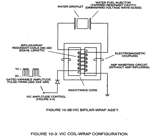
VIC Bifilar Wrap Coil-Assembly (10-3B) and VIC Dual Coil Wrap-Assembly (10-3A) both utilize either "E" & “I” and "U" Inductance Core configurations to concentrate Mutual Inductance Fields (Rpl/Rp2) in order to optimize Amp Inhibiting Process (750) of Figure (7-14).
Voltage to Amp Differential Ratio 2×
-
Performance Graph (750)
keeping amp-surge (inhibiting amp flow) to a minimal level [See Voltage Performance Graph (750) of Figure (7-14)] while enhancing Voltage Potential of Electrical Stress (64/RU-RU'a xxx 64/ST-ST'n) as additional Dual Choke Coils (56/62 _ SS56/62) are included in the stacked coil-array forming Voltage Intensifier Circuit (970) of Figure (10-1) as to (620) of figure (7-1)
-
Performance Graph (750)
Voltage Performance Graph (750) of Figure (7-14)