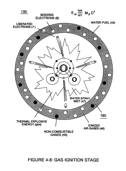
Figure (4-8)
Gas Ignition Stage
Also written Digital Inject Circuit S
How it is written
- (4-8) 18×
Drawings 5
-
Captioned as this figure · Electronic Circuit Design
-
Figure (4-8) · Water Fuel Injection System - Page 2
-
(100) of Figure (4-8) · In Application of Usage
-
(100) of Figure (4-8) · Voltage Intensifier Coil-Assembly
-
(100) of Figure (4-8) · Capacitance Reactance
On this figure 6
- 7 Energy Aperture
- 45 Non-Combustible Gases
- 100 Hydrogen Fracturing Process
- 180 Voltage Igniter Stage
- Ein —
- Md —
Where it is named · 18
Water Fuel Injection System - Page 2 2×
-
... which not only separates and splits the unlike atoms of the water molecule but also causes the unlike atoms (hydrogen atoms 77a /77b and oxygen atom 76) to experience electron ejection (230) of Figure (3-30) as to (71) of Figure (4-10) since voltage intensifier circuit (110) of Figure (4-9) inhibits and prevents electron flow to enter into gas ignition process (180), as further illustrated in Figure (4-8).
-
Figure (4-8)
Water Fuel Injection System - Page 3 5×
-
Figure (4-8)
-
Incoming ambient air gases (5a xxx 5n) become laser primed and ionized when passing through Ambient Air Ionizer (Gas Processor) (80) of Figure (4-6) as to (10) of Figure (4-1) since electron extraction circuit (120) of Figure (4-10) not only captures and consumes ejected electrons (7a xx 7n) of Figure (4-8);
-
Figure (4-8)
-
Injected non-combustible gases (45a xxx 45n) retards and controls the combustion rate of the Hydrogen Fracturing Process (100) of Figure (4-8) during gas-ignition.
In Application of Usage 2×
-
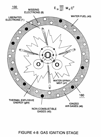
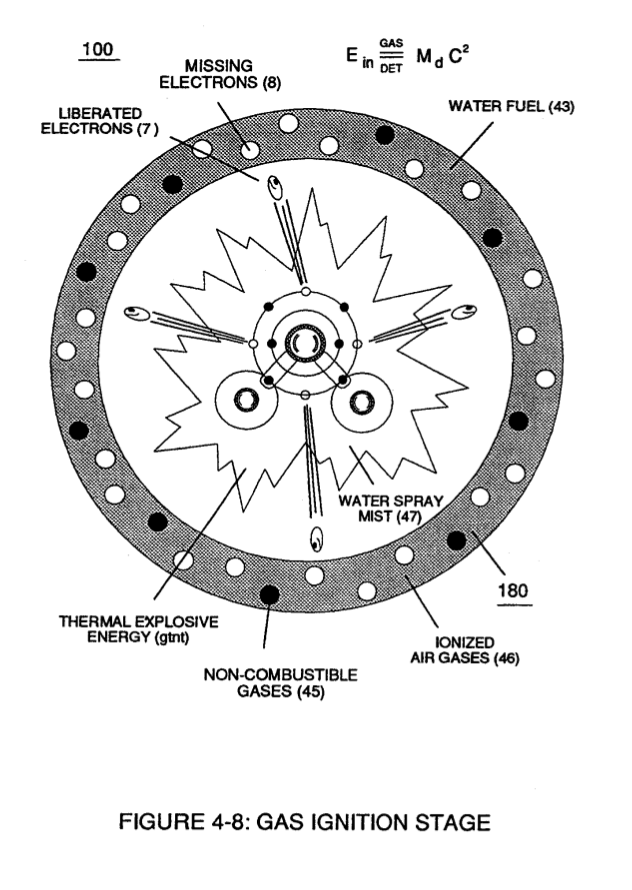
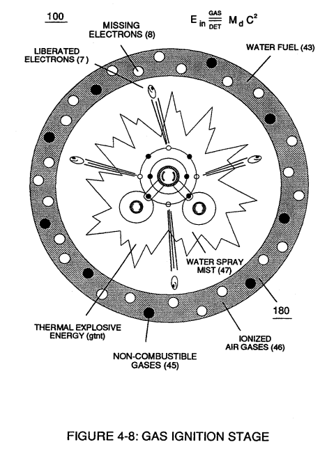
The Hydrogen Fracturing Process (390) of Figure (3-42) simply triggers and releases atomic energy (gtnt) from natural water (85) of Figure (3-26) by retarding and preventing the reformation of the water molecule being subjected to sub-critical state (520) of Figure (5-3) during thermal gas ignition (100) of Figure (4-8) as to (70) of Figure (4-5).
-
(100) of Figure (4-8)
Water Fuel Injector 1×
Voltage Intensifier Coil-Assembly 4×
-
(100) of Figure (4-8)
-
… leakage) by which "Voltage Intensity of Opposite Potential" (600) of Figure (6-3) can perform work to trigger Hydrogen Fracturing Process (520) of Figure (5-3) (Memo WFC 424 DA) as to (100) of Figure (4-8) (Memo WFC 423DA), as graphically denoted in (750) of Figure (7-14) of WFC memo (426) titled VIC Matrix Circuit - Instant Explosion of Water.
-
(100) of Figure (4-8)
Capacitance Reactance 2×
-
(100) of Figure (4-8)
Electron Bounce Phenomenon 2×
-
(100) of Figure (4-8)