(Vo)
Applied Voltage Amplitude
Also written voltage amplitude · Electrical Pulse Voltage amplitude · voltage potential · High Voltage Potential of Difference · voltage amplitude potential · zero voltage ground state · Voltage-Pulse Amplitude · Voltage Excitation
Where it is first named
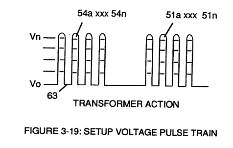
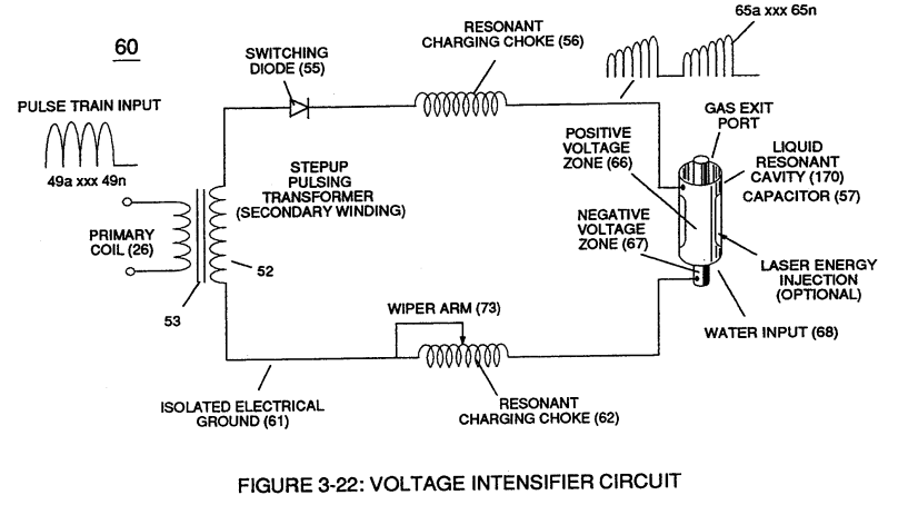
Pulsing transformer (26/52) of Figure (3-22) steps up voltage amplitude or voltage potential (Vo xxx Vn) of Figure (3-19) during pulsing operations.
How it is written
- (Vo xxx Vn) 7× with (V) Voltage Amplitude
- (Vo - Vn) 4× with (Vn) Voltage Potential
- (Vo) 2×
- (Vo xxx) 2×
- (VO - Va - Vb - Vc - Vn) 1× with (Va), (Vb) VIC Voltage Enhancement Circuit, (VC) Vacuum Gap, (Vn) Voltage Potential
- (Vo - Va -Vb - Vn) 1× with (Va), (Vb) VIC Voltage Enhancement Circuit, (Vn) Voltage Potential
- (Vo -Vn) 1× with (Vn) Voltage Potential
- (Vo xxx Va xxx V b - Vf xxx Vg xxx Vn) 1× with (V) Voltage Amplitude
Drawings 57
-
Figure (3-19) · Cell Driver Circuit (90)
-
Figure (3-19) · Voltage Intensifier Circuit (60)
-
Figure (3-23) · Voltage Intensifier Circuit (60)
-
Figure (3-23) · Voltage Dynamics
-
In both cases, electrical charge deflection or movement is directly related to applied voltage (65). · Voltage Dynamics
-
Ions or particle mass having the same or like electrical charges will move away from one another, as illustrated in (220) of Figure (3-29). · Voltage Dynamics
-
Figure (3-29) · Electrically Charged Water Molecule
-
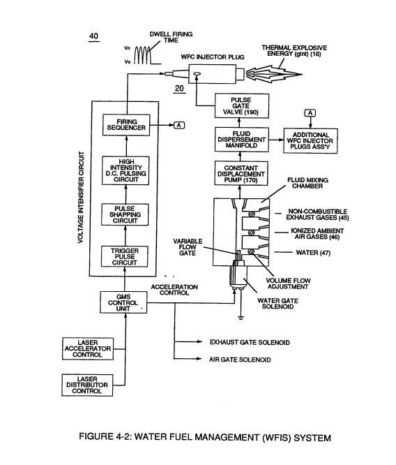
Water Fuel Injector Plug (40) of Figure (4-2) · Operational Parameters
-
The figure it sits on · WFC 422DA - Illustrations
-
The figure it sits on · WFC 422DA - Illustrations
-
The figure it sits on · WFC 422DA - Illustrations
-
The figure it sits on · Differential Air-Gas Inlet Control
-
(220) of Figure (18) · Water Fuel Injector (Taper Resonant Cavity Chamber)
-
The figure it sits on · Water Fuel Injector (Taper Resonant Cavity Chamber)
-
The Following Page 1-7 was not available · Water Fuel Injector (Taper Resonant Cavity Chamber)
-
Figure (4-2) · Water Fuel Injection System - Page 1
-
which simply uses Water Fuel Management (WFMS) System fluid-metering system (40) to control gas ignition (16), as illustrated in (40) of Figure (4-2). · Water Fuel Injection System - Page 4
-
Figure (5-5) · Resonant Propagation
-
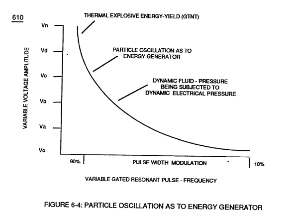
610 of Figure 6-4 · In Application of Usage
-
Figure (6-4) · In Application of Usage
-
The figure it sits on · Illustrations
-
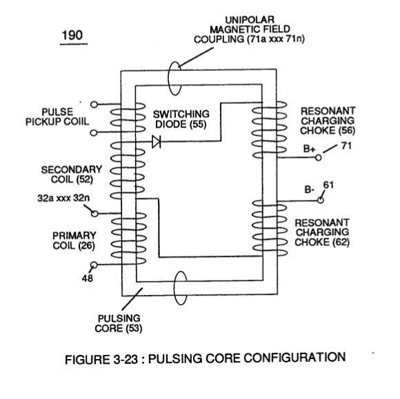
(190) of Figure (3-23) · Tri - Coil Construction
-
The figure it sits on · WFC 425 - Illustrations
-
(700) of Figure (7-9) · Instant Explosion of Water
-
Figure (7-13) · Inductance (FL)
-
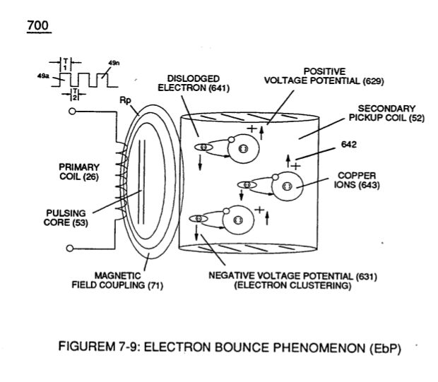
"Electron Bounce" phenomenon (700) of Figure (7-9) · Inductance Reactance (Rs - Cd - FL)
-
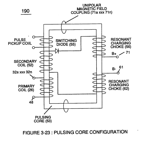
Inductance Pulsing-Core (190) of Figure (3-23) · Inductance Reactance (Rs - Cd - FL)
-
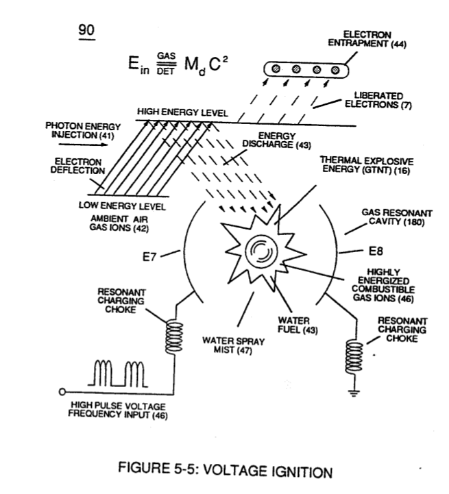
(90) of Figure (5-5) · Capacitance Reactance
-
"Electron Clustering" (Grouping/collecting negative charged particles at a given point) (700) of Figure (7-9) · Transformer Action
-
The figure it sits on · Electron Bounce Phenomenon
-
Voltage Dynamics (220) of Figure (3-29) · Electron Bounce Phenomenon
-
(700) of Figure (7-9) · Electron Bounce Phenomenon
-
... causing "electron clustering" (641a xxx 641n) to take place within Copper Wire Zone (52) during pulse on- time (T1) · Electron Bounce Phenomenon
-
(see 740 of Figure 7-13) · Voltage Amplitude Switch-Off
-
The figure it sits on · WFC 426 - Illustrations
-
The figure it sits on · 8-1 - Propagating "Resonant Action" By Voltage Tickling of State Space
-
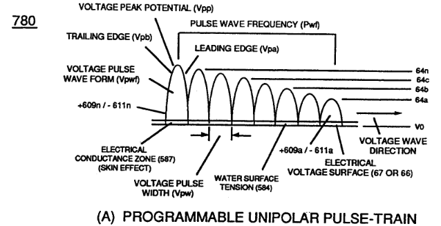
(780A) Figure (8-2) · 8-2 - Traveling Voltage Wave-Guides
-
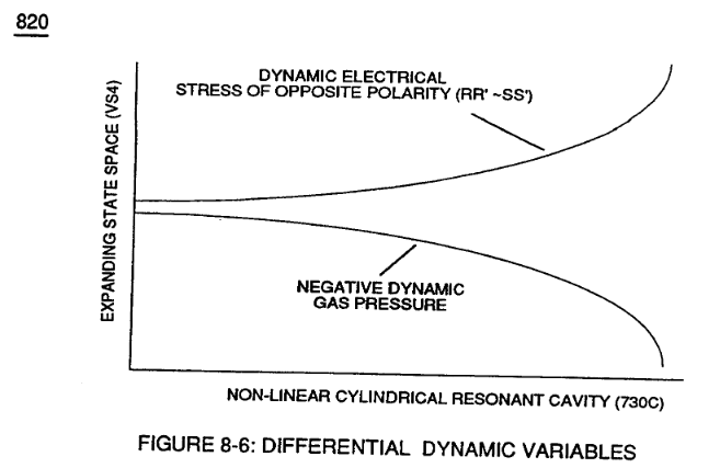
Figure (8-6) · 8-2 - Traveling Voltage Wave-Guides
-
(90) of Figure (5-5) · 8-2 - Traveling Voltage Wave-Guides
-
Figure (8-2) · 8-2 - Traveling Voltage Wave-Guides
-
(631) of Figure (7-9) · 8-3 - Electrical Voltage-Pulse Wave-Transmission
-
(780 B) of Figure (8-2) · 8-4 - State Space (Sp)
-
(780 A/B/C) of Figure (8-2) · 8-4 - State Space (Sp)
-
(40) of Figure (4-2) · 8-5 - Energy Vectoring (Ev)
-
Clipped Voltage Wave-form (780C) of Figure (8-2) · 8-5 - Energy Vectoring (Ev)
-
The figure it sits on · 8-6 - VIC Voltage Sync-Pulse Circuit
-
(820B) of Figure (8-6) · 8-7 - Application of Usage
-
(820C) of Figure (8-6) · 8-7 - Application of Usage
-
Figure (820A) of Figure (8-6) · 8-7 - Application of Usage
-
The figure it sits on · WFC 427 Illustrations
-
The figure it sits on · WFC 427 Illustrations
-
Voltage Dynamics (220) of Figure (3-29) · WFC Exhaust Air Reclaimer
-
Figure (10-3 A/B) · Propagating Electrical Stress
-
The figure it sits on · WFC 429 - Illustrations
-
The figure it sits on · WFC 429 - Illustrations
-
The figure it sits on · WFC 429 - Illustrations
-
The figure it sits on · Wobbling Effect
Where it is named · 26
Voltage Intensifier Circuit (60) 2×
-
voltage potential (Vo xxx Vn)
Pulsing transformer (26/52) of Figure (3-22) steps up voltage amplitude or voltage potential (Vo xxx Vn) of Figure (3-19) during pulsing operations.
-
voltage potential (Vo xxx Vn)
Voltage amplitude or voltage potential (Vo xxx Vn) is increased when secondary coil (52) is wrapped with more turns of wire.
Voltage Dynamics 1×
-
The higher the voltage potential (Vo xxx Vn), the greater "electrical attraction force" (qq') or "electrical repelling force" (ww') of Figure (3-29) is applied to electrical circuit (60) of Figure (3-22).
Resonant Action 1×
-
voltage amplitude (Vo xxx Yn)
By attenuating voltage amplitude (Vo xxx Yn) in conjunction with pulse-width (65a xxx 65n) allows voltage intensifier circuit (190) of Figure (3-23) to tune-in and match the resonant characteristics or resonant frequency of water bath (91) since water bath (91) always maintains its dielectric properties during pulsing operations.
Water Fuel Injection System 2×
-
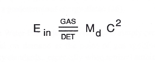
To lower Energy-flame temperature simply increase the amount of non-combustible gas (45a xxx) or reduced the fluid flow rate (45 / 46/ 47)) uniformly while lowering pulse voltage amplitude (xxx Vo).
-
To establish a predetermined or given Energy-flame temperature adjust fluid-medium (45 / 46 / 47)) and applied voltage amplitude (Vo xxx) independent of each other to obtain the desired results.
Water Fuel Injector (Taper Resonant Cavity Chamber) 1×
-
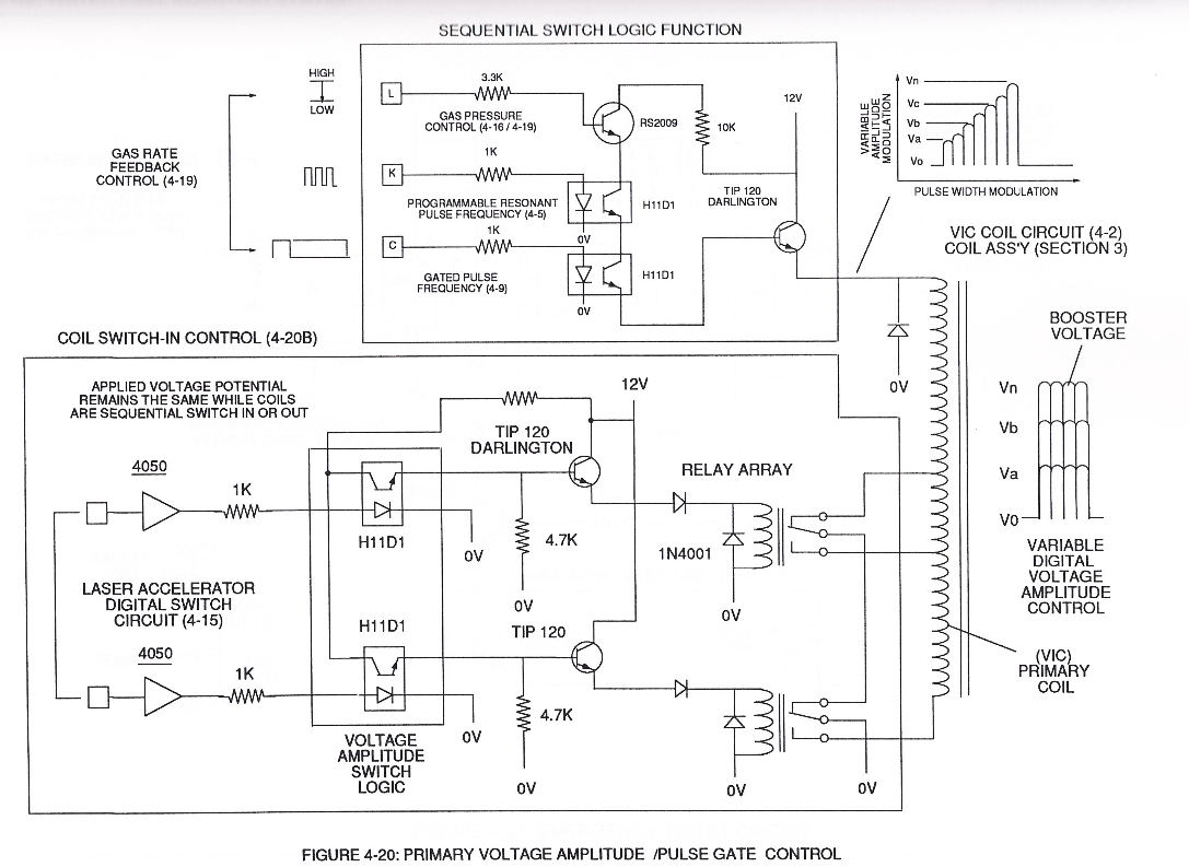
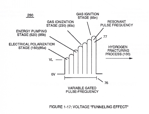
The resultant and newly formed gated Resonant Pulse-train (T1 + T2a xxx T1 + T2n) (58) voltage amplitude (Vo xxx Vn) is, now, attenuated by Sequential Voltage Amplitude Control Circuit (59) once step up Secondary Coil (53) produces a higher voltage level (xxxVL) above incoming pulse-train (210) since Secondary Coil (53) has a greater number of turns of wire.
Funneling Effect 1×
-
Attenuating variable voltage amplitude (72a xxx 72n) in conjunction with incoming gated pulse-train (210a xxx 210n), now, expands gated pulse width (76a xxx 76n) as voltage amplitudes (Vo xxx Vn) increases, forming step up voltage wave Form (77) of Figure (17).
Water Fuel Injection System - Page 2 1×
-
applied voltage amplitude (V0 xxx Vo)
To elevate Energy-flame-temperature still further, simply increase fluid-displacement (46/47) while maintaining or reducing the volume flow rate of non-combustible gases (45) during an increase of applied voltage amplitude (V0 xxx Vo) of Figure (4-2) as to Voltage Intensifier Circuit (110) of Figure (4-9) and Electron Extraction Circuit (120) of Figure (4-10).
Energy Pumping Action 2×
-
applied voltage amplitude (Vo xxx)
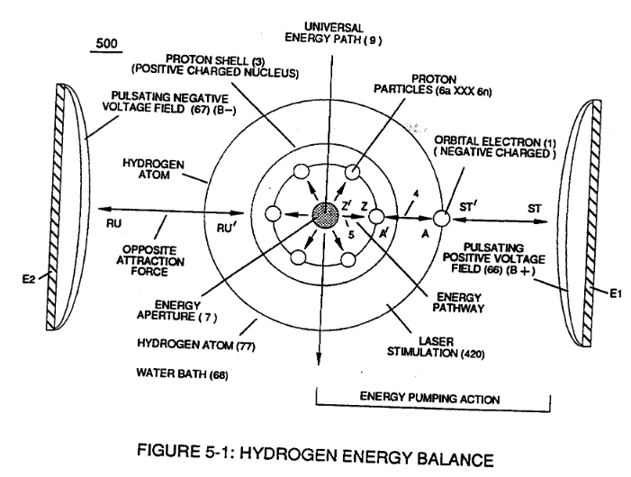
Interlocked together, the resultant "Electrical Tension of Forces" (4/5) is directly related to Voltage Intensity (ST - ST' / RU - RU' ) of applied voltage fields (66/67) which is variable as to applied voltage amplitude ( Vo xxx ). Increasing voltage amplitude ( xxx Vn) still further increases electrical tension (4 / 5 ) being applied to Energy Aperture (7) or vice versa.
-
This established increase or decrease in Electrical Pressure (4 / 5 ), now causes Energy Aperture (7) to either enlarge or become smaller as to applied voltage amplitude (VO xxx Vn), respectively.
Resonant Propagation 1×
-
applied voltage amplitude (Vo xxx Vn)
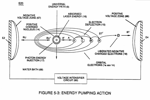
applied voltage amplitude (Vo xxx Vn) which is independent of Resonance Frequency is adjusted to cause water bath atoms to momentarily enter into Liquid-to-gas ionization state .... ejecting negative charged electrons …forming positive charged atoms having missing electrons ... forming negative charged atoms by electrons capture; as illustrated in (520) in Figure (5-3) as to Figure (5-4A) and Figure (5-4B).
In Application of Usage 1×
-
… applied traveling voltage wave-form (57) of Figure (6-2) of opposite electrical polarity (E9-66/ ElO-67) initiates the voltage-triggering process (600) of Figure (6-3) once maximum voltage deflection (VO - Va - Vb - Vc - Vn) of Figure (6-4) is achieved at Activation-Point (E9d) of Figure (6-2) ... releasing thermal Explosive Energy (gtnt) from the atomic level of the water molecule.
Inductance (FL) 1×
-
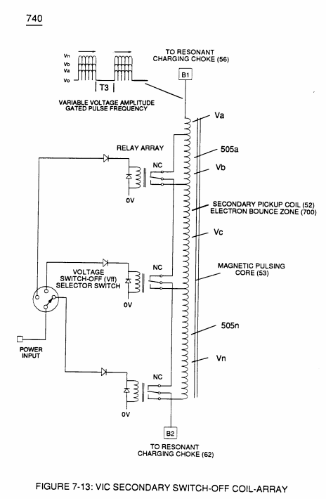
Component Interaction promotes Component Reactance during D.C. pulsing operations while allowing variable voltage amplitude (Vo - Va -Vb - Vn) of Figure (7-13) to be attenuated independently of Voltage Pulse frequency (49a xxx 49n), as so illustrated in (600) of Figure (6-3).
In-Line Circuit Components 1×
-
Voltage Amplitude (Vo xxx Va xxx V b - Vf xxx Vg xxx Vn)
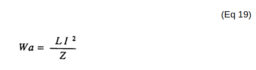
Inductance Reactance directly determines "Stored" Energy (Wa) which is controlled by input Voltage Potential attenuated or varied by way of Voltage Amplitude (Vo xxx Va xxx V b - Vf xxx Vg xxx Vn) of Figure (7-13) and/or Gated Pulse-Frequency (49a xxx 49n - T3 - 49a xxx 49n), or both.
Transformer Action 2×
-
Voltage Potential (Vo - Vn)
Magnetic Induction (71a - 71n) is determined by Inductance Permeability (μL) of core material (53) along with VIC circuit geometry ability to step up Voltage Potential (Vo - Vn) by way of "Transformer Action", and is expressed in the following equations:
-
Voltage Excitation (Vo -Vn)
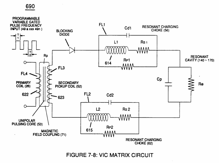
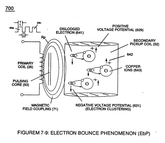
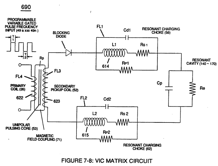
… to cause and inhibit electron flow (IF) since "electrons" magnetic field (547) of Figure (5-9) locks onto the electromagnetic fields of each energized choke coils (FL1/FL2) during Voltage Excitation (Vo -Vn) which, now, brings on and allows "Electron Bounce Phenomenon" (700) of Figure (7-9) to take place.
Electron Bounce Phenomenon 3×
-
High Voltage Potential of Difference (Vo - Vn)
High Voltage Potential of Difference (Vo - Vn) (SS' - 617 -RR') is accomplished when magnetic flux lines of force (71a xx 71n) (Rp) emanating away from closed-loop magnetic pulsing core (53) of Figure (190) penetrates Inductance coil-windings (52 …
-
Voltage Potential (Vo - Vn)
Sustaining and maintaining the resultant induced Voltage Potential (Vo - Vn) without "Electron Discharged" (inhibiting electron flow) through Choke Coil (62) while, at the same time, inhibiting (preventing) any additional or other electrons from entering into Secondary copper wire-zone (52) by way of Choke Coil (56) is herein called "Electron Bounce Phenomenon" (EbP), as illustrated in (700) of Figure (7-9).
-
Voltage Potential (Vo - Vn)
… icient of Inductance (F11/F12), Voltage Coefficient of Capacitance (Cd1/Cd2), Voltage Coefficient of Resistance (Rs1/Rs2), and Dielectric Coefficient of Water resistance (Re) allows Voltage Potential (Vo - Vn) of opposite electrical polarity to perform work (SS' _ 617 _ RR') without amp influxing, thus, not allowing the introduction of electron flow into Hydrogen Fracturing Process (90) of Figure (5-5) dur …
8-2 - Traveling Voltage Wave-Guides 2×
-
… 6-1) (WFC memo 425) ability to inhibit amp "influxing" (Electron Bounce Phenomenon EbP) during pulsing operations (49a xx 49n) allows voltage amplitude of pulse-frequency potential (T1a xxxT1n) as to (Vo -64a-64b -64c - Vn) of (780A) Figure (8-2) to be applied across cross-sectional circular-ring water bath (85) (donut shape) to cause Voltage Wave-Form (57) of Figure (6-2) to travel the entire longitudinal length of wat …
-
voltage amplitude potential (Vo - 64a - 64b - 64c - Vn)
... thereby, maintaining voltage amplitude potential (Vo - 64a - 64b - 64c - Vn) of Figure (8-6) without experiencing amp arc-over across Water-Gap (616) in any appreciable amount
8-3 - Electrical Voltage-Pulse Wave-Transmission 3×
-
Electrical Pulse Voltage amplitude (Vo - 64a - 64b- 64c - Vn)
Electrical Voltage-Pulse Wave-Transmission (583a xxx 583n), now formed, occurs along Electrical Conductance Zone (587) since applied Electrical Pulse Voltage amplitude (Vo - 64a - 64b- 64c - Vn) is time responsive (T1/T2a - T3 – T1/T2n) to incoming gated Voltage Pulse Frequency (49a xxx - 1'3 - xxx 49n).
-
Voltage-Pulse Amplitude (Vo xxx Vn)
Each Voltage Pulse duration time-period (T1 on time) from start to finish is directly related to applied Voltage-Pulse Amplitude (Vo xxx Vn) and reoccurring Voltage Pulse Frequency (49a xxx 49n) forming "Unipolar Voltage Pulse-Wave" (583) from zero voltage ground state (Vo) to a predetermined Voltage Level ( xxx 64 x - 64y - 64z - Vn) on …
-
zero voltage ground state (Vo)
… ish is directly related to applied Voltage-Pulse Amplitude (Vo xxx Vn) and reoccurring Voltage Pulse Frequency (49a xxx 49n) forming "Unipolar Voltage Pulse-Wave" (583) from zero voltage ground state (Vo) to a predetermined Voltage Level ( xxx 64 x - 64y - 64z - Vn) on the leading edge of the Voltage Pulse-Wave (Vpa) and, then, reversing voltage up swing to drop on the trailing edge (Vpb), completing …
8-4 - State Space (Sp) 1×
-
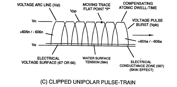
Clipped Unipolar Pulse Train (780C) is used to encourage further increase in atomic dwell-time capable of raising Atomic Energy Level (AEI) of the Water Atoms to even a higher energy-state before Snapping-Action occurs when Unipolar Pulse Wave (Upw) returns to ground state (Vo) after voltage propagation (Vpa/Vpb).