(V) · also written as a run, Va xxx Vn
Voltage Amplitude
Also written applied voltage amplitude · voltage potential · Opposite Voltage Potential · Voltage Intensity · Voltage levels of variance · maximum voltage deflection · Voltage Pulse-Potential · Voltage-Pulse Amplitude and 3 more
Where it is first named
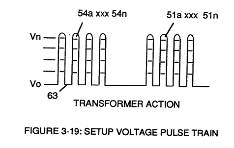
Analog voltage signal (32a xxx 32n) of Figure (3-15) allows pulse train (51a xxx 51n) voltage amplitude (V0 xxx Vn) of Figure (3-19) to vary from one up to twelve volts (battery supply 28 of Figure 3-6 by attenuating Laser Accelerator circuit (10) of Figure (3-5) via Hydrogen Gas Control Circuit (100).
How it is written
- (Vo xxx Vn) 7× with (Vo) Applied Voltage Amplitude
- (Va xxx Vn) 5×
- (xxx Vn) 5×
- (VL ~ Vn xxx) 3× with (VL) Voltage Intensity
- (Vo xxx Va xxx V b - Vf xxx Vg xxx Vn) 1× with (Vo) Applied Voltage Amplitude
- (Va xxx Vn/49a xxx 49n) 1× with (Vn) Voltage Potential, (49) Voltage Pulse frequency
- (VO xxx Vn) 1× with (Vo) Applied Voltage Amplitude
- (VL xx Va) 1× with (VL) Voltage Intensity
Va xxx Vn is Meyer's shorthand for a run of the same thing: Va is the first, Vn the last, and the x's stand for however many lie between. Every stage of the run is this one numeral. A pair before the letters, 583/602a, is a run of two things that go together, one of each per stage.
Drawings 100
-
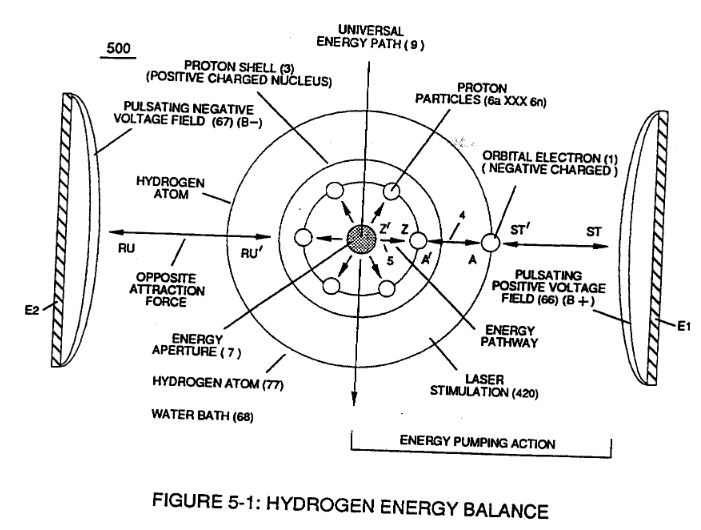
This established increase or decrease in Electrical Pressure (4 / 5 ), now causes Energy Aperture (7) to either enlarge or become smaller as to applied voltage amplitude (VO xxx Vn), respectively. · Energy Pumping Action
-
Figure (3-19) · Cell Driver Circuit (90)
-
Figure (3-19) · Voltage Intensifier Circuit (60)
-
Figure (3-28) · Voltage Intensifier Circuit (60)
-
Ohm's law of LC circuit (180) of Figure (3-28) in series is given by (Eq 5) · Voltage Intensifier Circuit (60)
-
Voltage (Vc) of Figure (3-28) across the capacitor is given by (Eq 7) · Voltage Intensifier Circuit (60)
-
Figure (3-25) · Voltage Intensifier Circuit (60)
-
In both cases, electrical charge deflection or movement is directly related to applied voltage (65). · Voltage Dynamics
-
Ions or particle mass having the same or like electrical charges will move away from one another, as illustrated in (220) of Figure (3-29). · Voltage Dynamics
-
Figure (3-29) · Electrically Charged Water Molecule
-
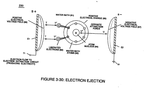
Figure (3-30) · Resonant Action
-
The figure it sits on · WFC 422DA - Illustrations
-
The figure it sits on · WFC 422DA - Illustrations
-
The figure it sits on · WFC 422DA - Illustrations
-
The figure it sits on · WFC 422DA - Illustrations
-
The figure it sits on · WFC 422DA - Illustrations
-
The figure it sits on · WFC 422DA - Illustrations
-
The figure it sits on · Differential Air-Gas Inlet Control
-
Electron Ejection Process (230) of Figure (29) · Water Fuel Injector (Taper Resonant Cavity Chamber)
-
The figure it sits on · Funneling Effect
-
Figure (3-30) · Water Fuel Injection System - Page 2
-
The figure it sits on · Energy Pumping Action
-
Figure (5-8) · Energy Pumping Action
-
(550) of Figure (5-8) · In Application of Usage
-
(230) of Figure (3-30) · In Application of Usage
-
(550) of Figure (5-8) · Covalent Switch-Off
-
(7) of Figure (5-8) · Energy Aperture of the Atom
-
(550) of Figure (5-8) · Solar Energy Actuator
-
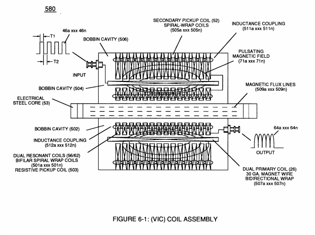
coil-structures (580) of Figure (6-1) · Voltage Intensifier Coil-Assembly
-
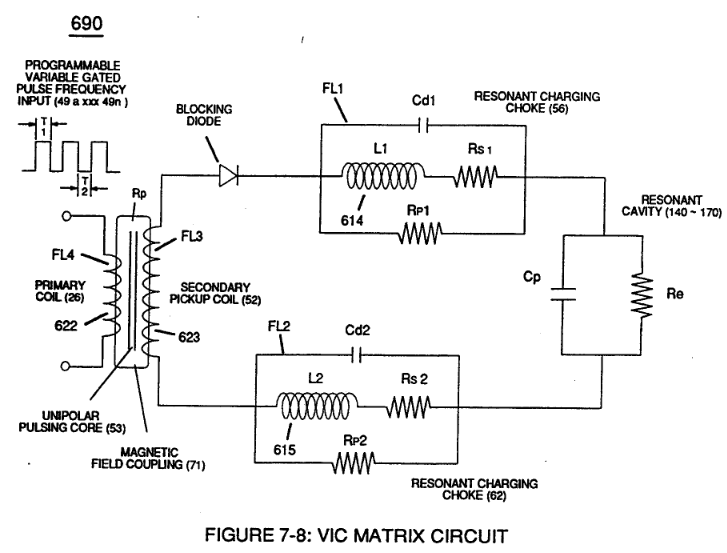
The figure it sits on · VIC Matrix Circuit
-
Voltage Intensifier Circuit (620) of Figure (7-1) · Instant Explosion of Water
-
(616) of Figure (7-11) · Instant Explosion of Water
-
(T2) of Figure (7-8) · Instant Explosion of Water
-
(620) of Figure (7-1) · Instant Explosion of Water
-
Figure (7-8) · Resistance (Rs)
-
(620) of Figure (7-1) · Resistance (Rs)
-
(690) of Figure (7-8) · Resistance (Rs)
-
Figure (7-13) · Inductance (FL)
-
(614) of Figure (7-1) · Inductance (FL)
-
(720) of Figure (7-11) · Inductance (FL)
-
(580) of Figure (6-1) · Inductance (FL)
-
(720, 616) of Figure (7-11) · Inductance (FL)
-
(690) of Figure (7-8) · Inductance (FL)
-
Inductor (614) of Figure (7-1) · Inductance (FL)
-
Capacitor (E9/E10) of Figure (7-11) · Inductance (FL)
-
(614) of (7-1) · Inductance (FL)
-
(720) of Figure (7-11) · Capacitance (Cd)
-
Figure (7-1) · Capacitance (Cd)
-
(690) of Figure (7-8) · Capacitance (Cd)
-
(690) of Figure (7-8) · Inductance Reactance (Rs - Cd - FL)
-
Figure (7-8) · Inductance Reactance (Rs - Cd - FL)
-
(620) of Figure (7-1) · Inductance Reactance (Rs - Cd - FL)
-
(580) of Figure (6-1) · Multi-layer Coil
-
(690) of Figure (7-8) · Taper Resonant Capacitor (ERt)
-
(see diagram 720 of Figure 7-11) · Taper Resonant Capacitor (ERt)
-
diagram 720 of Figure 7-11 · Taper Resonant Capacitor (ERt)
-
690 of Figure 7-8 · Circuit Resistance
-
Choke-Coil (62) of Figure (7-1) · Transformer Action
-
Voltage Dynamics (220) of Figure (3-29) · Electron Bounce Phenomenon
-
(52) of Figure (7-8) · Electron Bounce Phenomenon
-
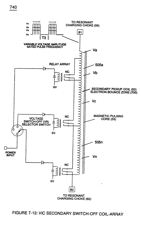
(see 740 of Figure 7-13) · Voltage Amplitude Switch-Off
-
The figure it sits on · WFC 426 - Illustrations
-
The figure it sits on · WFC 426 - Illustrations
-
The figure it sits on · WFC 426 - Illustrations
-
The figure it sits on · 8-1 - Propagating "Resonant Action" By Voltage Tickling of State Space
-
(580) of Figure (6-1) (WFC memo 425) · 8-2 - Traveling Voltage Wave-Guides
-
(720) of Figure (7-11) · 8-2 - Traveling Voltage Wave-Guides
-
(690) of Figure (7-8) · 8-2 - Traveling Voltage Wave-Guides
-
(770) of Figure(8-1) · 8-2 - Traveling Voltage Wave-Guides
-
(770) of Figure (8-1) · 8-3 - Electrical Voltage-Pulse Wave-Transmission
-
(52) of Figure (7-8) · 8-3 - Electrical Voltage-Pulse Wave-Transmission
-
(Cp) of Figure (7-8) · 8-4 - State Space (Sp)
-
(770 A) of Figure (8-1) · 8-4 - State Space (Sp)
-
(770 B) of Figure (8-1) · 8-4 - State Space (Sp)
-
(585) of Figure (8-1) · 8-4 - State Space (Sp)
-
(550 of Figure 5-8) · 8-4 - State Space (Sp)
-
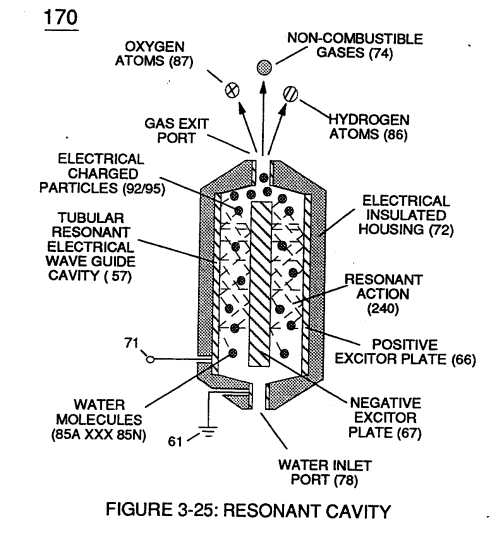
(170) of Figure (3-25) · 8-4 - State Space (Sp)
-
(770A) of Figure (8-1) · 8-5 - Energy Vectoring (Ev)
-
(612) of Figure (8-1) · 8-5 - Energy Vectoring (Ev)
-
(620) of Figure (7-1) · 8-6 - VIC Voltage Sync-Pulse Circuit
-
(690) of Figure (7-8) · 8-6 - VIC Voltage Sync-Pulse Circuit
-
(Cp) of (7-8) · 8-6 - VIC Voltage Sync-Pulse Circuit
-
The figure it sits on · WFC 427 Illustrations
-
The figure it sits on · WFC Development Objectives
-
Voltage Dynamics (220) of Figure (3-29) · WFC Exhaust Air Reclaimer
-
"Electrovalent Switch-off" phenomenon (550) of Figure (5-8) · WFC Exhaust Air Reclaimer
-
"Voltage Tickling of State Space" (770A) of Figure (8-1) · WFC Exhaust Air Reclaimer
-
"Voltage Tickling of State Space" (770B) of Figure (8-1) · WFC Exhaust Air Reclaimer
-
(690) of Figure (7-8) · Propagating Electrical Stress
-
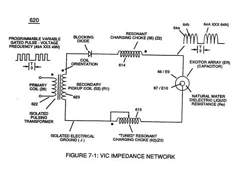
"Resonant Charging Choke" (56) of Figure (7-1) · Propagating Electrical Stress
-
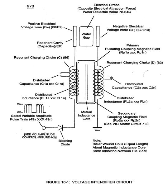
The programmable pulse-frequency (49a xxx 49n) of Figure (10-1) input is simply adjusted to tune-in to the dielectric property of the Water Molecule. · Propagating Electrical Stress
-
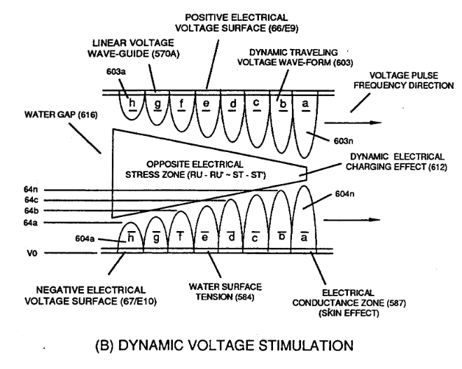
Dynamic Electrical Charging Effect (612) of Figure (8-1) · Propagating Electrical Stress
-
(580) of Figure (6-1) · Voltage to Amp Differential Ratio
-
(620) of figure (7-1) · Voltage to Amp Differential Ratio
-
hydrogen energy aperture (7) of (550) of Figure (5-8) · Optical Thermal Lens
-
The figure it sits on · Quartz Tube Configuration & Operational Parameters
-
... establishing variable Dynamic Electrical Charging Effect (612). · Quartz Tube Configuration & Operational Parameters
-
The figure it sits on · WFC 429 - Illustrations
-
The figure it sits on · Degaussing Radioactive Material
-
(970) of Figure (10-1) · VIC Switchover Circuit
Where it is named · 34
Voltage Intensifier Circuit (60) 4×
-
voltage amplitude (V0 xxx Vn)
Analog voltage signal (32a xxx 32n) of Figure (3-15) allows pulse train (51a xxx 51n) voltage amplitude (V0 xxx Vn) of Figure (3-19) to vary from one up to twelve volts (battery supply 28 of Figure 3-6 by attenuating Laser Accelerator circuit (10) of Figure (3-5) via Hydrogen Gas Control Circuit (100).
-
voltage potential (Vo xxx Vn)
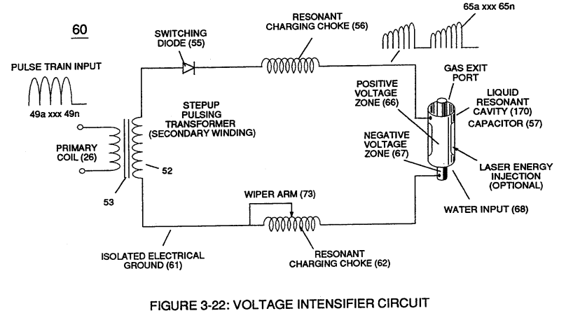
Pulsing transformer (26/52) of Figure (3-22) steps up voltage amplitude or voltage potential (Vo xxx Vn) of Figure (3-19) during pulsing operations.
-
voltage potential (Vo xxx Vn)
Voltage amplitude or voltage potential (Vo xxx Vn) is increased when secondary coil (52) is wrapped with more turns of wire.
-
voltage (Yo xxx Vn)
The value of inductor (56), value of capacitor (57), and the pulse-frequency (63) of voltage (Yo xxx Vn) being applied across the LC circuit determined the impedance of LC circuit (Figure 3-28).

Voltage Dynamics 1×
-
The higher the voltage potential (Vo xxx Vn), the greater "electrical attraction force" (qq') or "electrical repelling force" (ww') of Figure (3-29) is applied to electrical circuit (60) of Figure (3-22).
Resonant Action 3×
-
higher voltage levels (xxx Vn)
Subjecting and exposing water molecule (85) to even higher voltage levels (xxx Vn) (up to and beyond several thousand volts) causes water bath (91) of Figure (3-30) as to Figure (3-25) to go into a state of ionization by allowing opposite polarity forces (TT') and (UU') to eject one or more electrons (92a xxx 92n) from water bath atoms (93).
-
maximum voltage deflection (xxx Vn)
At resonance, electrical polarization process (160) interacts uniformly with liberated charged particles (92/95) of Figure (3-25) to obtain a even higher gas-yield (88) at maximum voltage deflection (xxx Vn).
-
applied voltage amplitude (xxx Vn)
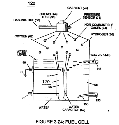
Insulated housing (72) prevents voltage coupling to water bath (68) which allows applied voltage amplitude (xxx Vn) to remain constant across water molecules (85a xxx 85n)
Gas Processor 1×
-
voltage amplitude (Va xxx Vn)
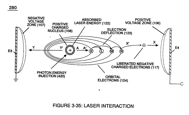
Applied voltage amplitude (Va xxx Vn), applied voltage pulse frequency (65a xxx 65n), and applied current pulse train (126a xxx 126n) are design variable to "tune-in" to the resonant properties of gas atom (101) while stimulating and performing gas process (260) which attenuates electrical force (AA') of Figure (3-35) to disrupt the mass equilibrium of gas atom (104).
Water Fuel Injector (Taper Resonant Cavity Chamber) 1×
-
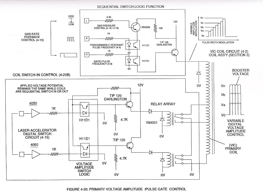
The resultant and newly formed gated Resonant Pulse-train (T1 + T2a xxx T1 + T2n) (58) voltage amplitude (Vo xxx Vn) is, now, attenuated by Sequential Voltage Amplitude Control Circuit (59) once step up Secondary Coil (53) produces a higher voltage level (xxxVL) above incoming pulse-train (210) since Secondary Coil (53) has a greater number of turns of wire.
Funneling Effect 6×
-
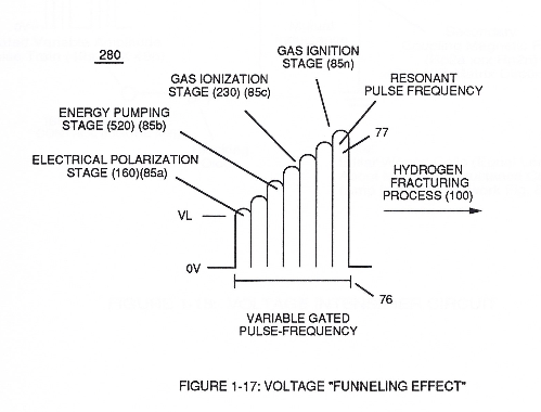
This resultant "Funneling Effect" (260), now, allows voltage amplitude (Vn) wave-form (58) to travel the length of Resonant Cavity Zone (35) from Start-Point (85a) to End-Point (85n) increasing voltage intensity (xxx VL = Vn) as parallel voltage surfaces (83/84) diminishes in size relationship (85a ~ 85n), as illustrated in (210) of Figure (17).
-
Voltage amplitude level VL of Pulse-wave (58) is predetermined (20,000 V.D.C. typically) to start and cause Electrical Polarization Process (160) at a relative rapid rate of gas production at segmental point (85a) when voltage point (VL xx Va) is reached.
-
In alternate form, Core-Slug (73) is replaced by a series of Choke Coils (77a xxx 77n) arranged in such a way as to increase voltage Intensity (Voltage Pulse Amplitude) (VL ~ Vn xxx) digitally by sequentially switching-on / switching -off Choke Coils (77a xxx 77n) to allow applied Voltage Intensity (VL ~ Vn xxx) to be placed across Voltage Expander Coils (78a xxx 78n) in direct r …
-
Voltage Intensity (VL ~ Vn xxx)
… uch a way as to increase voltage Intensity (Voltage Pulse Amplitude) (VL ~ Vn xxx) digitally by sequentially switching-on / switching -off Choke Coils (77a xxx 77n) to allow applied Voltage Intensity (VL ~ Vn xxx) to be placed across Voltage Expander Coils (78a xxx 78n) in direct relationship to electrically energized shunt-coil (76).
-
Voltage Intensity (VL ~ Vn xxx)
For example, as adjacent Shunt-Coil (76b) is switch-on while, simultaneously, Choke Coil (76a) is switch-off by Electronic Switch Circuit (79), Voltage Intensity (VL ~ Vn xxx) is increased due to inductance / capacitance of Voltage Expander Coil (78a) which is, now, added to Electrical Circuit (250) by electrical pathway (82a) since electromagnetic coupling field (76b) pre …
-
Attenuating variable voltage amplitude (72a xxx 72n) in conjunction with incoming gated pulse-train (210a xxx 210n), now, expands gated pulse width (76a xxx 76n) as voltage amplitudes (Vo xxx Vn) increases, forming step up voltage wave Form (77) of Figure (17).
Energy Pumping Action 2×
-
voltage amplitude (xxx Vn)
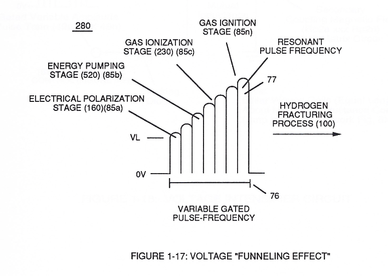
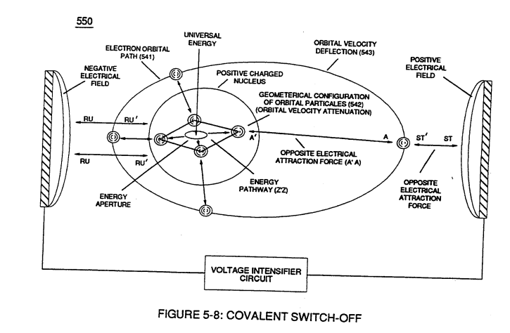
Interlocked together, the resultant "Electrical Tension of Forces" (4/5) is directly related to Voltage Intensity (ST - ST' / RU - RU' ) of applied voltage fields (66/67) which is variable as to applied voltage amplitude ( Vo xxx ). Increasing voltage amplitude ( xxx Vn) still further increases electrical tension (4 / 5 ) being applied to Energy Aperture (7) or vice versa.
-
This established increase or decrease in Electrical Pressure (4 / 5 ), now causes Energy Aperture (7) to either enlarge or become smaller as to applied voltage amplitude (VO xxx Vn), respectively.
Resonant Propagation 1×
-
applied voltage amplitude (Vo xxx Vn)
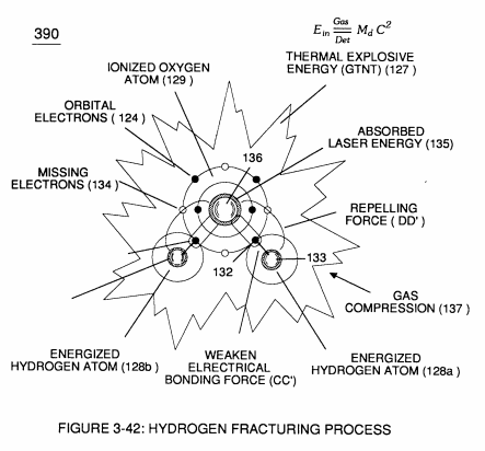
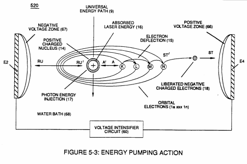
applied voltage amplitude (Vo xxx Vn) which is independent of Resonance Frequency is adjusted to cause water bath atoms to momentarily enter into Liquid-to-gas ionization state .... ejecting negative charged electrons …forming positive charged atoms having missing electrons ... forming negative charged atoms by electrons capture; as illustrated in (520) in Figure (5-3) as to Figure (5-4A) and Figure (5-4B).
Instant Explosion of Water 1×
-
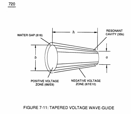
… f unipolar gated pulse-wave (64a xxx T3 xxx 64n) without experiencing "signal distortion" or "signal degradation" (preventing transformer ringing during signal propagation) as elevated voltage levels ( - xx Vc- xx Vd - xx Vn) while allowing the reduction of Capacitor-Gap (Cp) (616) of Figure (7-11) width spacing (57 of Figure 3- 25 ~35 of Figure 6-2) (typically .060 - .010) respectively as illustrated in Tubular Resonant …
Inductance Reactance (Rs - Cd - FL) 2×
-
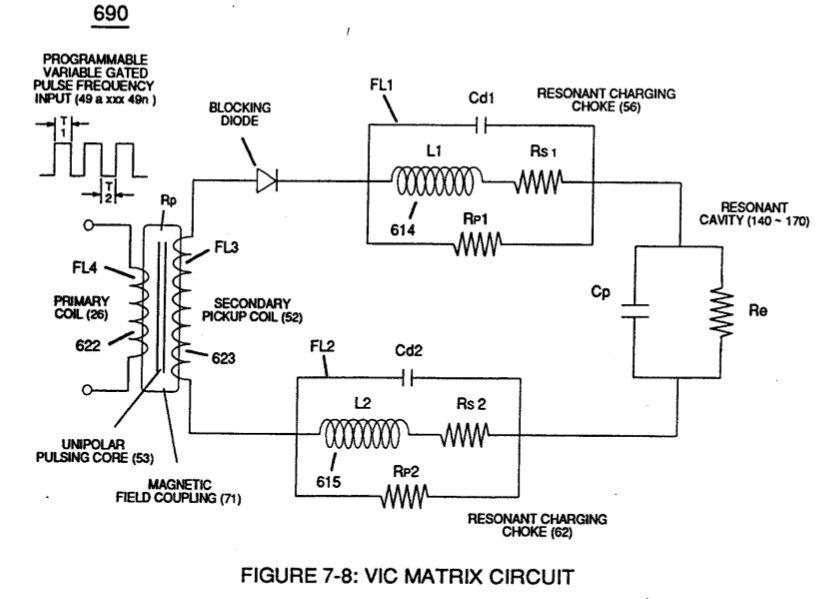
At elevated or higher amplitude voltage levels (xxx Ve xxx Vf xxx Vn), primary electromagnetic coupling field (Rp) of Figure (7-8) transmitted by way of Inductance Pulsing-Core (190) of Figure (3-23) as to VIC Coil Assembly (580) of Figure (6-1) enters into and passes …
-
… and passes through both Inductors (L1/L2) simultaneously and offers not only further electron-flow restriction (Rp1/Rp2) to both Inductor Chokes (56/62) but automatically increases voltage potential (xxx V g xxx Vh xxx Vn) of opposite voltage intensity of equal magnitude (66/67) across Resonant Cavity (140 -170)
In-Line Circuit Components 1×
-
Voltage Amplitude (Vo xxx Va xxx V b - Vf xxx Vg xxx Vn)
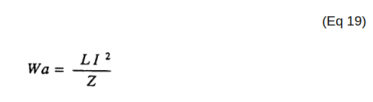
Inductance Reactance directly determines "Stored" Energy (Wa) which is controlled by input Voltage Potential attenuated or varied by way of Voltage Amplitude (Vo xxx Va xxx V b - Vf xxx Vg xxx Vn) of Figure (7-13) and/or Gated Pulse-Frequency (49a xxx 49n - T3 - 49a xxx 49n), or both.
Voltage Amplitude Switch-Off 1×
-
Voltage levels of variance (Va xxx Vn)
Voltage levels of variance (Va xxx Vn) is achieved by simply switching-in or switching-out the member of Secondary Coil-cavities (505a xx 505n) (see 740 of Figure 7-13) in direct relationship to Taper Resonant Voltage surfaces (E9/10) of Figure (6-2) which acts and performs as a "Voltage Amplifier" when Compressional Wave-form (B) of Figure (7-12) is intensified at Exit Port (32) of Figure (6-2).
8-3 - Electrical Voltage-Pulse Wave-Transmission 2×
-
Voltage-Pulse Amplitude (Vo xxx Vn)
Each Voltage Pulse duration time-period (T1 on time) from start to finish is directly related to applied Voltage-Pulse Amplitude (Vo xxx Vn) and reoccurring Voltage Pulse Frequency (49a xxx 49n) forming "Unipolar Voltage Pulse-Wave" (583) from zero voltage ground state (Vo) to a predetermined Voltage Level ( xxx 64 x - 64y - 64z - Vn) on …
-
Voltage Level (xxx 64 x - 64y - 64z - Vn)
… tage-Pulse Amplitude (Vo xxx Vn) and reoccurring Voltage Pulse Frequency (49a xxx 49n) forming "Unipolar Voltage Pulse-Wave" (583) from zero voltage ground state (Vo) to a predetermined Voltage Level ( xxx 64 x - 64y - 64z - Vn) on the leading edge of the Voltage Pulse-Wave (Vpa) and, then, reversing voltage up swing to drop on the trailing edge (Vpb), completing Voltage-wave (583).
8-4 - State Space (Sp) 1×
-
Voltage Amplitude (xx 64a - 64b - 64c - Vn)
In terms of Particle Oscillation (Poe) as a Energy-Generator (EGpo), if Voltage Arc Line (Val) length is extended while Voltage Amplitude (xx 64a - 64b - 64c - Vn) is adjusted to higher Voltage Peak-Potential (Vpp) then greater atomic interaction (585) of Figure (8-1) (see WFC memo 424 titled Atomic Energy Balance of Water, once again) occurs when particle osci …
WFC Exhaust Air Reclaimer 1×
-
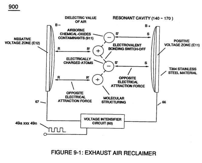
… Environmental Protection Agency (EPA) clean Air Act similar in construction to Voltage Intensifier Circuit (110) of Figure (4-9), WFC Exhaust Air Reclaimer (900) of Figure (9-1) utilizes opposite electrical attraction force (RR' - SS') of voltage potential (Va xxx Vn) to separate the atoms of the Nitric Oxide NO molecule (typically < 1ppm when running on water) by overcoming Electrovalent Attraction Force (q - q') that exist between the polar-charged Nitrogen (B+) …
Propagating Electrical Stress 2×
-
Voltage Potential (Va xxx Vn)
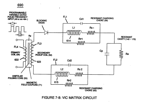
… 0) of Figure (7-8) is composed of two copper wires "Bifilar" wound (wrapped) about a magnetic induction core to allow amp restriction (minimizing current leakage) while encouraging "Voltage Potential"(Va xxx Vn) across the water molecule to perform WFC "Electrical Polarization Process", as so illustrated in Figure (7-1) WFC memo (426) titled VIC Matrix Circuit.
-
Voltage Pulse-Potential (Va xxx Vn/49a xxx 49n)
… The length and diameter size of the copper-wire spiral wrapped coil (56/62) of Figure (10-1) being paired together and electrically energized in conjunction with applied Voltage Pulse-Frequency determines how much "Amp Leakage" will occur across capacitor Gap (Cp) while "Voltage Pulse-Potential" (Va xxx Vn/49a xxx 49n) of "Opposite polarity" (B+/B-) is/are allowed to be applied across "Electrical Voltage Plates" (Voltage-Zones) (66/67).
Voltage to Amp Differential Ratio 1×
-
… l (SS56/62) to maximize mutual inductance coil-field (Rp2) (adding Rp1+Rp2) of (690) of Figure (7-8) to cause coil capacitance (Cda xxx Cdn) to help maintain and even increase pulse voltage amplitude (xxx Vn + Vn 1 + Vn2 + Vn .... etc.) while the resistive value (Rs2) of SS Coil-Wire (SS56/62) performs the work of further resisting the flow of amps not inhibited by both self-Inductance fields (Rpl + Rp2), as so illustrated in (690) …
Optical Thermal Lens 1×
-
Opposite Voltage Potential (Va xxx Vn)
The Energy Pumping Stage (520) of Figure (5-3) as to (500) of Figure (5-1) attenuates the hydrogen energy aperture (7) of (550) of Figure (5-8) when applied Opposite Voltage Potential (Va xxx Vn) (49a xxx 49n) (B+/B-) produces pulsating Electrical Stress Wave-form (opposite electrical attraction force) (RU/RU' - ST/ST'a xxx RU/RU' ST/ST'n) during Pulsing Operations.
VIC Switchover Circuit 2×
-
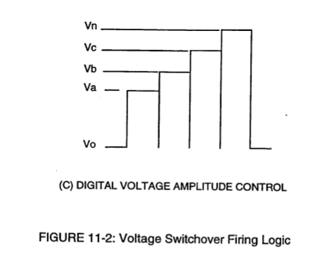
Voltage intensity (952/953) is, therefore, directly determined by the number of turns of each coil (957/958) as to the applied voltage amplitude of incoming pulse-wave ( ... xxx Vn) (1060) of Figure (11-2c).
-
Varying the gated pulse-width (T4A f T4B), attenuating voltage amplitude (xxx Vn), and the Switchover pulse frequency rate (Sopr), collectively determines the rate by which the water temperature rises as the water medium (68) travels through the Differential Voltage Wave-Guild (1040), as so illustrated in (1060) of Figure (11-2) as to (1040) of Figure (11-6).