(730) · also written as a run, 730a xxx 730n
Traveling Electrical Voltage Wave-forms
Also written linear cylindrical resonant cavity · Travelling Voltage Wave-forms
Where it is first named
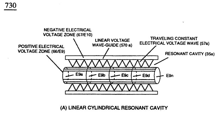
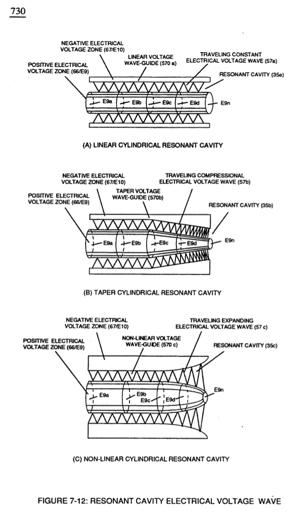
At each progressive point of diminishing circumference surface-area (E9a - b - c - d - E9n) voltage amplitude intensity increases (Vna - b - c - d - Vnn) uniformly, as illustrated in (600) of Figure (6-3) as to Travelling Voltage Wave-forms (730a - b - c) of Figure (7-12), see WFC Memo (426).
How it is written
- (730) 8×
- (730a - b - c) 2×
730a xxx 730n is Meyer's shorthand for a run of the same thing: 730a is the first, 730n the last, and the x's stand for however many lie between. Every stage of the run is this one numeral.
Drawings 17
-
(750) of Figure (7-14) · Inductance (FL)
-
(730) of Figure (7-12) · Taper Resonant Capacitor (ERt)
-
Traveling Electrical Voltage Wave-forms (730a - b - c) of Figure (7-12) · Electron Bounce Phenomenon
-
Carries this number · Mode of Operability
-
Carries this number · WFC 426 - Illustrations
-
Carries this number · WFC 426 - Illustrations
-
(730A) of Figure (7-12) · 8-2 - Traveling Voltage Wave-Guides
-
(570) of Figure (7-12) · 8-2 - Traveling Voltage Wave-Guides
-
(730) of Figure (7-12) · 8-5 - Energy Vectoring (Ev)
-
(840) of Figure (8-10) · 8-6 - VIC Voltage Sync-Pulse Circuit
-
(850) of Figure (8-11) · 8-6 - VIC Voltage Sync-Pulse Circuit
-
(730A) of Figure (7-12) · 8-7 - Application of Usage
-
Carries this number · WFC 427 Illustrations
-
Carries this number · WFC 427 Illustrations
-
Carries this number · WFC 427 Illustrations
-
Compressional Wave-form (B) of Figure (7-12) · Voltage Amplitude Switch-Off
-
(730C) of Figure (7-12) · 8-7 - Application of Usage
Where it is named · 10
Water Fuel Injector 1×
-
Travelling Voltage Wave-forms (730a - b - c)
At each progressive point of diminishing circumference surface-area (E9a - b - c - d - E9n) voltage amplitude intensity increases (Vna - b - c - d - Vnn) uniformly, as illustrated in (600) of Figure (6-3) as to Travelling Voltage Wave-forms (730a - b - c) of Figure (7-12), see WFC Memo (426).
Taper Resonant Capacitor (ERt) 2×
-
... each resonant cavity design acting and functioning as a Voltage Wave-guide (570) and gap-size (35) sufficient enough to allow the "Quenching Effect" to take place, as illustrated in (730) of Figure (7-12) as to (370) of Figure (3-40).
-
(730) of Figure (7-12)
Capacitance Reactance 2×
-
Capacitor (ER) should remain relatively small due to the dielectric value of water to obtain maximum Thermal Explosive Energy-Yield (16a xxx 16n) of Figure (4-5) and subsequently establishing Quenching Circuit (370) of Figure (3-40) to prevent gas ignition inside traveling voltage wave-guide (590) of Figure (6-2) as to (730) of Figure (7-12)
-
(730) of Figure (7-12)
Electron Bounce Phenomenon 1×
-
Traveling Electrical Voltage Wave-forms (730a - b - c)
Traveling Electrical Voltage Wave-forms (730a - b - c) of Figure (7-12)
Mode of Operability 1×
-
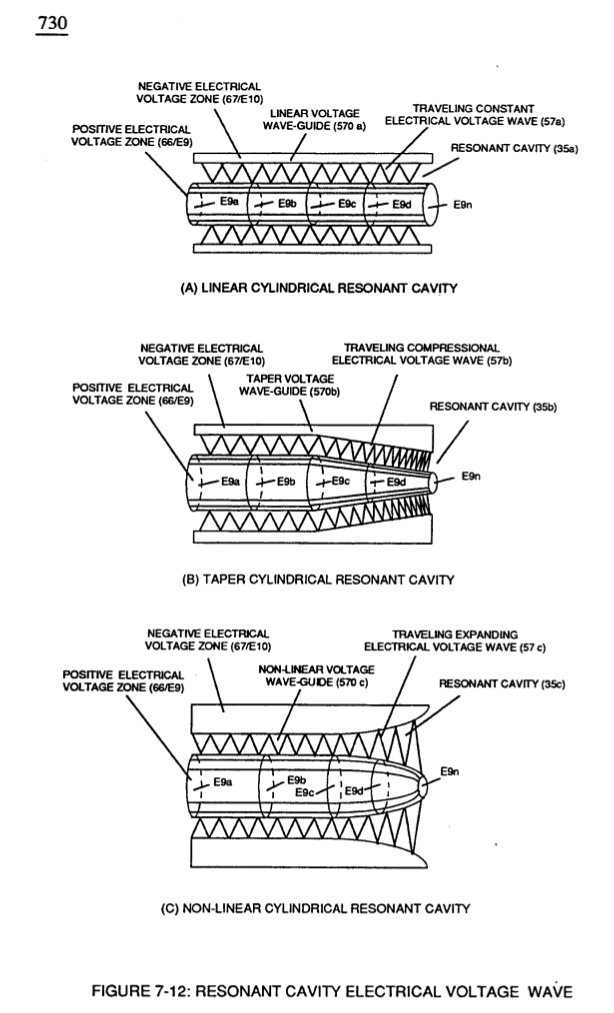
... increasing Thermal Explosive Energy-yield (gtnt) to higher energy-levels (gtnta xxx gtntn) beyond applied excitation voltage (Vn) by simply altering Voltage Surfaces (35b/35c) as in reference to Linear Voltage Surfaces (35a), as illustrated in (730) of Figure (7-12).
8-5 - Energy Vectoring (Ev) 2×
-
The "mode of operability" of determining the "Operational Parameters" of adjusting the thermal explosive energy (gtnt) exiting from nozzle-port (32) of Figure (4-5) as to (40) of Figure (4-2) is directly related to the characteristics of the applied Voltage Pulse Potential (Vpp) Wave-form (s) (Vpwt) and the geometrical configuration of Resonant Cavity (90) of Figure (4-7) as to (730) of Figure (7-12).
-
(730) of Figure (7-12)
VIC Switchover Circuit 1×
-
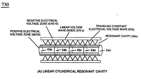
linear cylindrical resonant cavity (730)
In like manner as to linear cylindrical resonant cavity (730) of Figure (7-12), the Differential Voltage Wave-Guide (1040) of (1010) of Figure (11-1) as to Figure (11-6) is constructed in such a way as to allow a smaller tube to be placed inside a much larger tube having space relationship to allow water to pass there between, as so pictorially shown in (170) of Figure (3-25).