Figure (3-23)
Pulsing Core Configuration
How it is written
- (3-23) 22×
Drawings 6
-
Figure (3-23) · Voltage Intensifier Circuit (60)
-
Figure (3-23) · Voltage Dynamics
-
Captioned as this figure · WFC 422DA - Illustrations
-
(190) of Figure (3-23) · Tri - Coil Construction
-
Inductance Pulsing-Core (190) of Figure (3-23) · Inductance Reactance (Rs - Cd - FL)
-
Captioned as this figure · Electron Bounce Phenomenon
On this figure 19
- 23 Analog Voltage Level Output
- 52 Secondary Coil
- 53 Pulsing Core
- 56 Resonant Charging Choke
- 62 Resonant Charging Chokes
- 65 Voltage Potential
- 66 Positive Voltage Potential
- 67 Opposite Polarity
- 71 Magnetic Field Coupling
- 91 Water Bath
- 160 Electrical Polarization Process
- 190 Voltage Intensifier Circuit
- 502 —
- 505 Secondary Coil-cavities
- 506 —
- 530 Energy Recycling Spectrum
- VIC Resonant Cavity Voltage Intensifier Circuit
- Vo Applied Voltage Amplitude
- Y Voltage Amplitude
Where it is named · 22
Analog Voltage generator (40) 1×
Voltage Intensifier Circuit (60) 7×
-
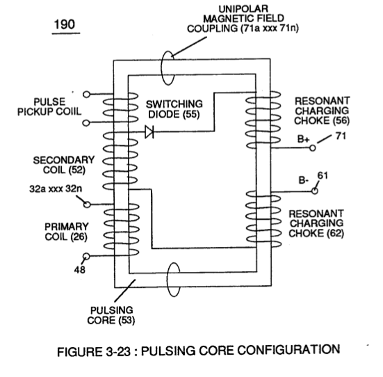
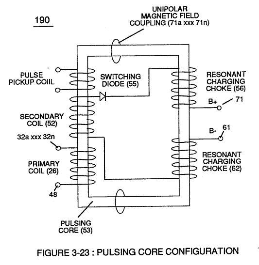
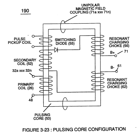
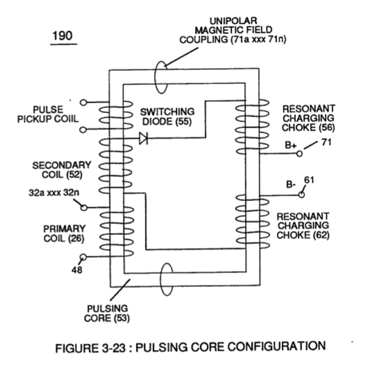
The resultant signal coupling ( 65a xx 65n ) of Figure (3-21) is accomplished since primary coil (26), pulsing core (53), secondary coil (52), switching diode (55), resonant charging choke (56), resonant cavity assembly (170), natural water (68), and variable resonant charging choke (62) forms Voltage Intensifier Circuit (60) of Figure (3-22), as illustrated in Figure (3-22) as to Figure (3-23).
-
Figure (3-23)
-
Amp restriction beyond "resonant action" occurs when unipolar magnetic field coupling (71) of Figure (3-23) is allowed to simultaneously drop (pulsating magnetic field) across both resonant charging chokes (56/62) during pulsing operations since electron mass is an electromagnetic entity which is subject to inductor fields (56/62) produced by pulsating magnetic field (71a xxx 71n) of Figure (3-23).
-
Amp restriction beyond "resonant action" occurs when unipolar magnetic field coupling (71) of Figure (3-23) is allowed to simultaneously drop (pulsating magnetic field) across both resonant charging chokes (56/62) during pulsing operations since electron mass is an electromagnetic entity which is subject to inductor fields (56/62) produced by pulsating magnetic field (71a xxx 71n) of Figure (3-23).
-
Inherently, then, pulsing core (53) of Figure (3-23) aids amp restriction while voltage intensifier circuit (190) is being "tuned" (adjusting pulse train 49a xxx 49n pulse-frequency 63 via pulse frequency generator 70 of figure 3-5) to match the resonant frequency properties of water bath (68) of Figure (3-22), as illustrated in Fuel Cell (120) of Figure (3-24).
-
Figure (3-23)
Voltage Dynamics 2×
-
Figure (3-23)
Electrically Charged Water Molecule 2×
-
… ) can alter the electromagnetic properties of a atom since electromagnetic force is dependent on the movement of charged particles in a electrostatic field voltage Intensifier circuit (190) of figure (3-23), now, allows voltage to dissociates water molecule (85) by overcoming electrostatic bonding force (qq') between unlike atoms (76n7) while restricting amp flow, as illustrated in (160) of Figure (3-26 …
-
Figure (3-23)
Electrical Polarization process 2×
-
… otential (65) across Excitor plates (E1/E2) (voltage zones 66/67) of Figure (3-29) as to Figure (3-26) while inhibiting and preventing electron flow within voltage intensifier circuit (190) of Figure (3-23) causes water molecule (210) of Figure (3-27) to separate into its component parts (released hydrogen and oxygen gases) by pulling away (utilizing opposite attraction forces SS' and RR') its charged w …
-
Figure (3-23)
Resonant Action 1×
-
By attenuating voltage amplitude (Vo xxx Yn) in conjunction with pulse-width (65a xxx 65n) allows voltage intensifier circuit (190) of Figure (3-23) to tune-in and match the resonant characteristics or resonant frequency of water bath (91) since water bath (91) always maintains its dielectric properties during pulsing operations.
Water Fuel Injector 1×
Tri - Coil Construction 4×
-
Resonant Choke Coils (56/62) of Figure (3-23) (Memo WFC 422 DA) are composed of 430F or 430FR inductance stainless steel film coated (hi dielectric value) wire (typically .004 Ga. …
-
Secondary pickup coil (52) of Figure (3-23) is, also, composed of individual spiral wrapped coils (505a xxx 505n) (typically .002 Ga. magnet wire) electrically connected in sequential order to form bobbin cavity (506) which is placed on top of and in space relationship to primary coil cavity (504).
-
Resonant bobbin assembly (503), primary bobbin assembly (504), and secondary bobbin assembly (506), now, make up and structurally forms voltage intensifier (VIC) coil-assembly (530) of Figure (5-6) when electrical steel core material (53) forms a close-loop magnetic induction pathway centrally through and around (VIC) coil-assembly (530), as schematically illustrated in (190) of Figure (3-23) (Memo WFC 422 DA).
-
(190) of Figure (3-23)
Inductance Reactance (Rs - Cd - FL) 2×
-
At elevated or higher amplitude voltage levels (xxx Ve xxx Vf xxx Vn), primary electromagnetic coupling field (Rp) of Figure (7-8) transmitted by way of Inductance Pulsing-Core (190) of Figure (3-23) as to VIC Coil Assembly (580) of Figure (6-1) enters into and passes through both Inductors (L1/L2) simultaneously and offers not only further electron-flow restriction (Rp1/Rp2) to both Inductor Cho …
-
Inductance Pulsing-Core (190) of Figure (3-23)