(10)
Led Pickup Circuit
Also written Water Fuel Injector Assembly · Water Fuel Injection System · Laser Accelerator Circuit · Water Fuel Injector Kit · Water Fuel Injector kits · WFC injector assembly · Extraction Circuit · water supply and 1 more
Where it is first named
Laser Accelerator Circuit (10) of Figure (4) which is a component part of Laser Accelerator Assembly (20) of Figure (3-10) uses a GaAs infrared emitting diode (1) of figure (3-9) to trigger a SDP8611 Optoschmitt light receiver (2) of Figure (3-9) from quiescent state ( output logic high ... …
How it is written
- (10) 32×
- (E9/10) 2× with (E9) Capacitor
Drawings 139
-
Stanley A. Meyer Page 10 of 28 · WFC 417 — WFC 417
-
Stanley A. Meyer Page 25 of 28 · WFC 417 — WFC 417
-
Stanley A. Meyer Page 28 of 28° · WFC 417 — WFC 417
-
Carries this number · Electromagnetic Enhancement
-
Carries this number · Magnetic Field Enhancement
-
RE is the dielectric constant of natural water. Ohm's Law as to applied electrical power, which is (Eq 10) · VIC Resistance
-
Oscillation (back and forth movement) of electrically charged particles by way of voltage deflection is hereinafter called "Resonant Action", as illustrated in Figure (1-10). · Voltage Dissociation of The Water Molecule
-
Carries this number · Gas Grid System
-
Led Pickup Circuit (10) of Figure (3-9) · Laser Accelerator Assembly
-
Light-gate (9) integrated with led pickup circuit (10) make up Laser Accelerator assembly (20), as shown in Figure (3-10). · Laser Accelerator Assembly
-
Figure (3-12) · Acceleration Control Circuit (30)
-
Figure (3-5) · Acceleration Control Circuit (30)
-
Figure (3-12) · Acceleration Control Circuit (30)
-
Toggling action at full-scale deflection (13a xxx 13n) occurs in the range of (10) kHz or above and thus, allows instant response to driver's acceleration demands. · Acceleration Control Circuit (30)
-
Figure (3-12) · Acceleration Control Circuit (30)
-
Analog Voltage Circuit (40), as shown in Figure (3-5) · Acceleration Control Circuit (30)
-
Figure (3-5) · Acceleration Control Circuit (30)
-
Figure (3-5) · Analog Voltage generator (40)
-
Ohm's law as to applied electrical power, which is (Eq 10) · Voltage Intensifier Circuit (60)
-
(340) of Figure (3-38) · Gas Modulator Process
-
engine cylinder (102) of Figure (3-38) · Gas Processor
-
Laser Accelerator (20) of Figure (3-10) · Laser Distributor
-
Figure (3-5) · Laser Distributor
-
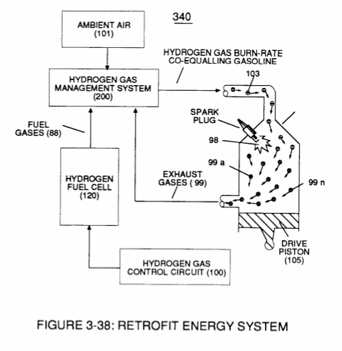
reciprocating WFC Fuel-kits can be similar to Car design (340); · Aviation Application
-
Carries this number · WFC 422DA - Illustrations
-
Carries this number · WFC 422DA - Illustrations
-
Carries this number · WFC 422DA - Illustrations
-
Carries this number · WFC 422DA - Illustrations
-
Carries this number · WFC 422DA - Illustrations
-
Carries this number · WFC 422DA - Illustrations
-
Carries this number · Water Fuel Injection System
-
3-7 VIC Amp Inhibitor Coil Ass'y · Voltage Intensifier Coil Assembly
-
Carries this number · Voltage Intensifier Coil Assembly
-
Carries this number · Electronic Circuit Design
-
Carries this number · Electronic Circuit Design
-
Carries this number · Electronic Circuit Design
-
Carries this number · Electronic Circuit Design
-
Carries this number · Electronic Circuit Design
-
Carries this number · Electronic Circuit Design
-
Carries this number · Electronic Circuit Design
-
Carries this number · Electronic Circuit Design
-
Carries this number · Electronic Circuit Design
-
Carries this number · Electronic Circuit Design
-
Carries this number · Electronic Circuit Design
-
Carries this number · Electronic Circuit Design
-
Carries this number · Electronic Circuit Design
-
Carries this number · Electronic Circuit Design
-
Carries this number · Electronic Circuit Design
-
Carries this number · Electronic Circuit Design
-
Carries this number · Electronic Circuit Design
-
Carries this number · Electronic Circuit Design
-
Carries this number · Electronic Circuit Design
-
Carries this number · Electronic Circuit Design
-
Carries this number · Electronic Circuit Design
-
Carries this number · Electronic Circuit Design
-
Carries this number · Electronic Circuit Design
-
Carries this number · Differential Air-Gas Inlet Control
-
Water Fuel Injection System (10) of Figure (1) · Water Fuel Injector (Taper Resonant Cavity Chamber)
-
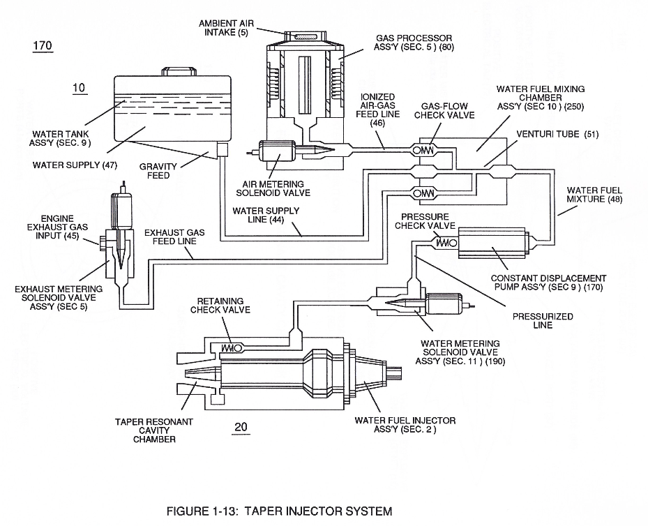
(170) of Figure (13) · Water Fuel Injector (Taper Resonant Cavity Chamber)
-
(170) of Figure (13) · Water Fuel Injector (Taper Resonant Cavity Chamber)
-
Fluid Displacement Pump (170) of Figure (13) · Water Fuel Injector (Taper Resonant Cavity Chamber)
-
Carries this number · Water Fuel Injector (Taper Resonant Cavity Chamber)
-
Carries this number · Water Fuel Injector (Taper Resonant Cavity Chamber)
-
thereby, attenuating voltage amplitude (voltage intensity) beyond Secondary Coil (53) voltage levels (71), as illustrated in (220) of Figure (18). · Funneling Effect
-
Carries this number · Steam Resonator Assembly
-
Carries this number · Cover Page
-
Figure (4-1) · Water Fuel Injection System - Page 1
-
Figure (4-10) · Water Fuel Injection System - Page 2
-
610 of Figure 6-4 · In Application of Usage
-
Figure (6-4) · In Application of Usage
-
(570) of Figure (5-10) · Energy Aperture of the Atom
-
(570, 7, 9) of Figure (5-10) · Solar Energy Actuator
-
Carries this number · WFC 425 - Illustrations
-
(710) of Figure (7-10) · Inductance (FL)
-
(760) of Figure (7-15) · Inductance (FL)
-
(710) of Figure (7-10) · Capacitance (Cd)
-
Carries this number · Multi-layer Coil
-
(760) of Figure (7-15) · Circuit Resistance
-
... each bobbin cavity adhering to equation (Eq 20), as illustrated in (710) of Figure (7-10). · Transformer Action
-
(710) of Figure (7-10) · Transformer Action
-
Traveling Electrical Voltage Wave-forms (730a - b - c) of Figure (7-12) · Electron Bounce Phenomenon
-
(E9/10) of Figure (6-2) · Voltage Amplitude Switch-Off
-
Carries this number · Mode of Operability
-
Carries this number · WFC 426 - Illustrations
-
Carries this number · WFC 426 - Illustrations
-
Carries this number · WFC 426 - Illustrations
-
(730A) of Figure (7-12) · 8-2 - Traveling Voltage Wave-Guides
-
(570) of Figure (7-12) · 8-2 - Traveling Voltage Wave-Guides
-
(770) of Figure(8-1) · 8-2 - Traveling Voltage Wave-Guides
-
(770) of Figure (8-1) · 8-3 - Electrical Voltage-Pulse Wave-Transmission
-
(770 A) of Figure (8-1) · 8-4 - State Space (Sp)
-
(730) of Figure (7-12) · 8-5 - Energy Vectoring (Ev)
-
(612) of Figure (8-1) · 8-5 - Energy Vectoring (Ev)
-
Carries this number · 8-6 - VIC Voltage Sync-Pulse Circuit
-
(840) of Figure (8-10) · 8-6 - VIC Voltage Sync-Pulse Circuit
-
(730A) of Figure (7-12) · 8-7 - Application of Usage
-
Carries this number · WFC 427 Illustrations
-
Carries this number · WFC 427 Illustrations
-
"FullSystem" development (10) of Figure (4-1) · WFC Development Objectives
-
Energy Aperture (570) of Figure (5-10) · WFC Development Objectives
-
Carries this number · WFC 428 - Illustrations
-
Figure (10-3 A/B) · Propagating Electrical Stress
-
(990) of Figure (10-3) · Propagating Electrical Stress
-
The programmable pulse-frequency (49a xxx 49n) of Figure (10-1) input is simply adjusted to tune-in to the dielectric property of the Water Molecule. · Propagating Electrical Stress
-
Dynamic Electrical Charging Effect (612) of Figure (8-1) · Propagating Electrical Stress
-
of Figure (10-5) · Voltage to Amp Differential Ratio
-
Carries this number · Voltage to Amp Differential Ratio
-
Figure (10-3A) · Voltage to Amp Differential Ratio
-
... emitting Coherent Energy Wave-Form (917), as so illustrated in (980) of Figure (10-2). · Optical Thermal Lens
-
Carries this number · WFC 429 - Illustrations
-
Carries this number · WFC 429 - Illustrations
-
Carries this number · WFC 429 - Illustrations
-
Carries this number · WFC 429 - Illustrations
-
Carries this number · WFC 429 - Illustrations
-
Carries this number · WFC 429 - Illustrations
-
Carries this number · Gyroscopic Spiking Effect
-
WFC Figure (5-10) · WFC Atomic Degaussing Process
-
Carries this number · Wobbling Effect
-
Carries this number · WFC 430-2 Illustrations
-
Carries this number · WFC 430-2 Illustrations
-
Carries this number · WFC 430-2 Illustrations
-
Carries this number · WFC 430-2 Illustrations
-
dual unipolar voltage pulse circuit (1010) of Figure (11-1) · Voltage Flexing Process
-
(1030) of figure (11-3) · Voltage Flexing Process
-
voltage intensifier circuit (990) of Figure (10-3) · VIC Switchover Circuit
-
(970) of Figure (10-1) · VIC Switchover Circuit
-
Differential Voltage Wave-Guild (1040B) · Electrical Crossover Switching Circuit
-
When (B+/B+ - B-/B- / 1030B) switch function is activated, switch terminals (T1/T2 - T3/T4) are closed. · Electrical Crossover Switching Circuit
-
The figure it sits on · Laser Accelerator Assembly
-
Figure (3-1) · Voltage Amplitude Control Circuit (50)
-
To further prevent voltage fluctuation during resonant action, Phase Lock Loop technique of Pulse Indicator circuit (110) is utilized during pulsing operations. · Resonant Action
-
Figure (3-1) · Laser Distributor
-
Hydrogen Fuel-Gas Assembly (450) of Figure (3-1) · Operational Parameters
-
The figure it sits on · WFC 422DA - Illustrations
-
3-5 Outer Core Bobbin · Voltage Intensifier Coil Assembly
-
The figure it sits on · Voltage Intensifier Coil Assembly
-
(57) of Figure (6-2) · In Application of Usage
-
Activation Process (590) of Figure (6-2) · Voltage Intensifier Coil-Assembly
-
(590) of Figure (6-2) · Capacitance (Cd)
Where it is named · 34
Laser Accelerator Assembly 6×
-
Laser Accelerator Circuit (10)
Laser Accelerator Circuit (10) of Figure (4) which is a component part of Laser Accelerator Assembly (20) of Figure (3-10) uses a GaAs infrared emitting diode (1) of figure (3-9) to trigger a SDP8611 Optoschmitt light receiver (2) of Figure (3-9) from quiescent state ( output logic high ... …
-
Led Pickup Circuit (10)
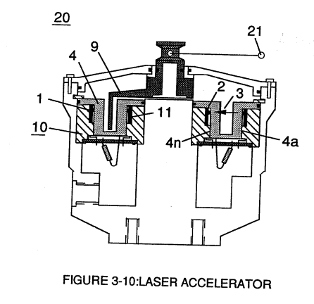
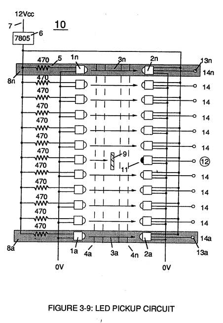
Grouping additional optical circuits (8a xxx 8n) in an inline or linear arrangement, now, forms Led Pickup Circuit (10) of Figure (3-9), as shown in Figure assembly (20) of Figure (3-10).
-
Longevity and reliability of component life is typically 100,000 hours since led pickup circuit (10) of figure (3-9) utilizes no mechanical contacts to perform the sequential logic switch function.
-
led pickup circuit (10)
Light-gate (9) integrated with led pickup circuit (10) make up Laser Accelerator assembly (20), as shown in Figure (3-10).
-
Led Pickup Circuit (10)
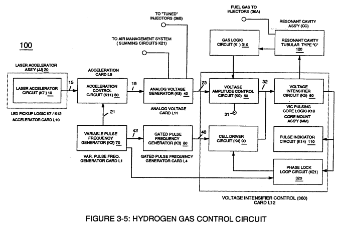
If light emitting diodes (led) (la xxx In) of figure (8) are electrically disconnected from D.C. power supply (6), then Led Pickup Circuit (10) outputs are switch to "low" logic state (l2a xxx 12n) which disallows "low" logic state signal (12), resulting in a "shut-down" condition to Hydrogen Gas Control Circuit (200) of Figure (3-1).
Acceleration Control Circuit (30) 2×
-
Led Pickup Circuit (10)
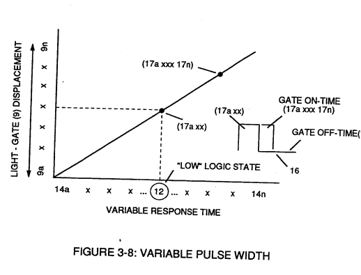
Since Led Pickup Circuit (10) of Figure (3-9) operates up to 100 kHz range or above, electrical sensitivity of Opto-circuit (8) provides a instantaneous response to Driver's acceleration, de-acceleration, or cruise control demands.
-
Toggling action at full-scale deflection (13a xxx 13n) occurs in the range of (10) kHz or above and thus, allows instant response to driver's acceleration demands.
Voltage Intensifier Circuit (60) 1×
-
Laser Accelerator circuit (10)
Analog voltage signal (32a xxx 32n) of Figure (3-15) allows pulse train (51a xxx 51n) voltage amplitude (V0 xxx Vn) of Figure (3-19) to vary from one up to twelve volts (battery supply 28 of Figure 3-6 by attenuating Laser Accelerator circuit (10) of Figure (3-5) via Hydrogen Gas Control Circuit (100).
Aviation Application 2×
-
Water Fuel Injector kits (10)
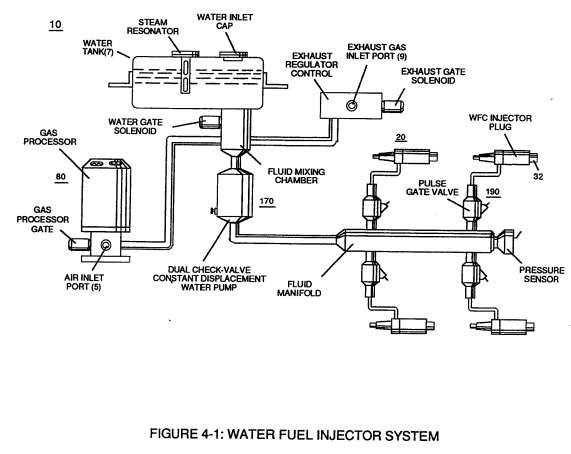
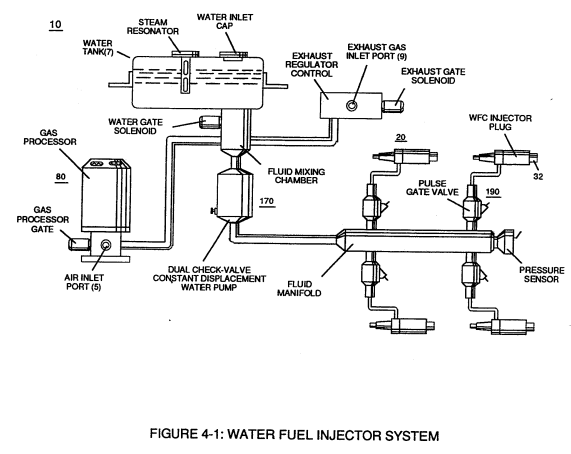
whereas, Water Fuel Injector kits (10) of figure (4-1) can alternately be used as a self-contained Fuel-unit having no pre-pressurized vessel which converts water directly in thermal explosive energy (gtnt) on demand, as illustrated in WFC memo 423 DA.
-
Water Fuel Injector Assembly (10)
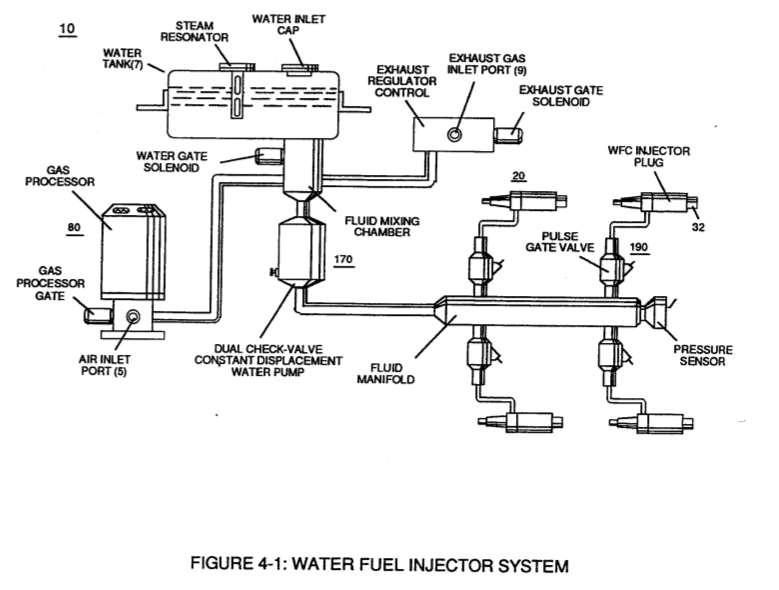
In terms of mechanical interfacing: Water Fuel Injector Assembly (10) of Figure (4-1) can replace standard fuel-injector ports of existing jet engines as shown in (150) of Figure (4-13); or be utilized in Furnace Nozzle Assembly (140) of Figure (4-12) for grain dryers or conventional\heating systems;
Operational Parameters 2×
-
Water Fuel Injector Assembly (10)
Coupling and subsequently integrating Hydrogen Gas Management (GMS) system (440) with either Hydrogen Fuel-Gas Assembly (450) of Figure (3-1) or Water Fuel Injector Assembly (10) of Figure (4-1) as to Water Fuel Management (WFMS) System (40) of Figure (4-2), now, sets up a full engineering system-approach on how to use Water as a "New" fuel-source.
-
Water Fuel Injector Assembly (10)
Water Fuel Injector Assembly (10) of Figure (4-1)
Water Fuel Injection System 6×
-
Water Fuel Injector Kit (10)
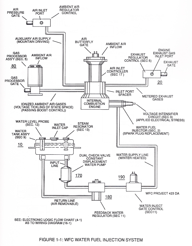
Whereas, Water Fuel Injector Kit (10) of Figure (1) can alternately be used as a self-contained Fuel-unit having no pressurized vessel which converts water directly into thermal explosive energy (gtnt) on demand, as illustrated (10) of Figure (1) as to Figure (40) of Figure (2B 1-2).
-
Whereas, Water Fuel Injector Kit (10) of Figure (1) can alternately be used as a self-contained Fuel-unit having no pressurized vessel which converts water directly into thermal explosive energy (gtnt) on demand, as illustrated (10) of Figure (1) as to Figure (40) of Figure (2B 1-2).
-
Operationally, Water Fuel injector assembly (10) of Figure (1) as to (40) of Figure (2B) performs several functions simultaneously to produce thermal explosive energy-yield (gtnt) (16) on demand:
-
Incoming ambient air gases (5a xxx 5n) become laser primed and ionized when passing through Ambient Air Ionizer (Gas Processor) (80) of Figure (4) as to (10) of Figure (1) since electron extraction circuit (120) of Figure (8) not only captures and consumes ejected electrons (7a cx 7n) of Figure (6); but, also prevents electron flow into destabilizing gas process (180), as so illustrated in Figure (3B).
-
WFC injector assembly (10) of Figure (1) as to (30) of Figure (2A) is design variable to be retrofitable by replacing fossil-fuel injector ports affixed to jet engines (see Figure 11), heating systems (Figure 10), rockets engi …
-
Water Fuel Injector Plug (20 / 30), as illustrated in (40) of Figure (2B) as to (10) of Figure (1).
Water Fuel Injector (Taper Resonant Cavity Chamber) 3×
-
Water Fuel Injection System (10)
releasing thermal explosive energy (gtnt) via flame projection (16) of Figure (3B) as to Figure (14), Water Fuel Injection System (10) of Figure (1) as to (170) of Figure (13) incorporates and uses Taper Resonant Cavity Chamber (180) of Figure (14) to enhance operational parameters of Hydrogen Fracturing Process (100) of Figure (6) …
-
water supply (10)
In like manner, water supply (10) of Figure (170), non-combustible gases (45) (Engine Exhaust gases), and ambient air ionized gases (46) (air gases having missing electrons) are uniformly intermixed when moving into, passing through and beyond fluid mixing chamber (250) of Figure (13) by way of venturi tube-cavity (51)...
Water Fuel Injection System - Page 1 3×
-
Water Fuel Injector Kit (10)
Whereas, Water Fuel Injector Kit (10) of Figure (4-1) can be alternately be used as a self-contained Fuel-unit having no pressurized vessel which converts water directly into thermal explosive energy (gtnt) on demand, as illustrated (10) of Figure (4-1) as to Figure (40) of Figure (4-2).
-
Whereas, Water Fuel Injector Kit (10) of Figure (4-1) can be alternately be used as a self-contained Fuel-unit having no pressurized vessel which converts water directly into thermal explosive energy (gtnt) on demand, as illustrated (10) of Figure (4-1) as to Figure (40) of Figure (4-2).
-
Operationally, Water Fuel injector assembly (10) of Figure (4-1) as to (40) of Figure (4-2) performs several function simultaneously to produce thermal explosive energy-yield (gtnt) (16) on demand:
Water Fuel Injection System - Page 2 1×
-
Extraction Circuit (10)
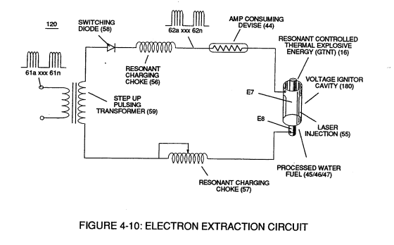
Voltage Igniter Stage (180) of Figure (4-5) as to Voltage Intensifier Circuit (110) Figure (4-9) as to Extraction Circuit (10) of Figure (4-10) performs several functions simultaneously to initiate and trigger thermal explosive energy-yield (gtnt) (16) beyond normal gas burning levels:
Water Fuel Injection System - Page 3 2×
-
Incoming ambient air gases (5a xxx 5n) become laser primed and ionized when passing through Ambient Air Ionizer (Gas Processor) (80) of Figure (4-6) as to (10) of Figure (4-1) since electron extraction circuit (120) of Figure (4-10) not only captures and consumes ejected electrons (7a xx 7n) of Figure (4-8);
-
(10) of Figure (4-1)
Water Fuel Injection System - Page 4 2×
-
WFC injector assembly (10)
WFC injector assembly (10) of Figure (4-1) as to (30) of Figure (4-2) is design variable to be retrofitable by replacing fossil-fuel injector ports affixed to jet engines (see Figure 4-13)
-
... especially when ionized ambient air gases (400 xxx 46n) and non-combustible gases (45a xxx 45n) are intermixed with water supply (47) prior to entering Water Fuel Injector Plug (20/30), as illustrated in (40) of Figure (4-2) as to (10) of Figure (4-1).
Voltage Amplitude Switch-Off 2×
-
surfaces (E9/10)
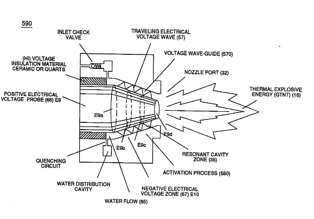
Voltage levels of variance (Va xxx Vn) is achieved by simply switching-in or switching-out the member of Secondary Coil-cavities (505a xx 505n) (see 740 of Figure 7-13) in direct relationship to Taper Resonant Voltage surfaces (E9/10) of Figure (6-2) which acts and performs as a "Voltage Amplifier" when Compressional Wave-form (B) of Figure (7-12) is intensified at Exit Port (32) of Figure (6-2).
-
(E9/10) of Figure (6-2)
WFC Development Objectives 2×
-
The primary Purpose/objective of Water Fuel Injection System (590) of Figure (6-2) as to "FullSystem" development (10) of Figure (4-1) is, in the realm of scientific quest, to help reverse the damage being done to "Earth Ecological Life Support System" by first of all encouraging the use of "Water" as a new "Fuel" source
-
"FullSystem" development (10) of Figure (4-1)