Figure (7-9)
Figure (7-9)
How it is written
- (7-9) 18×
Drawings 5
-
(700) of Figure (7-9) · Instant Explosion of Water
-
"Electron Bounce" phenomenon (700) of Figure (7-9) · Inductance Reactance (Rs - Cd - FL)
-
"Electron Clustering" (Grouping/collecting negative charged particles at a given point) (700) of Figure (7-9) · Transformer Action
-
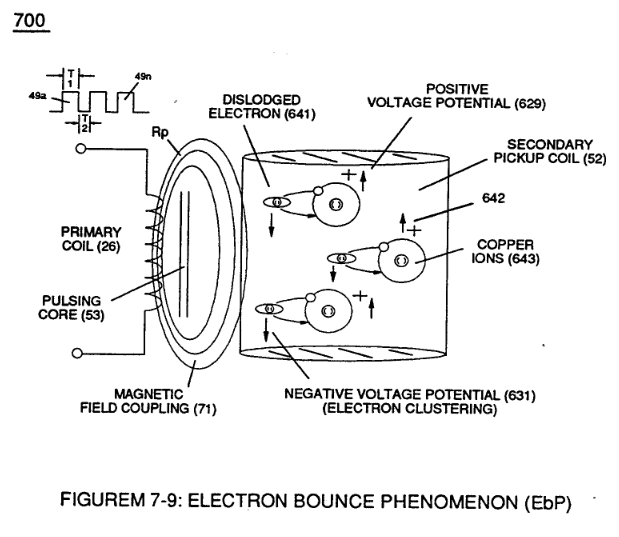
(700) of Figure (7-9) · Electron Bounce Phenomenon
-
(631) of Figure (7-9) · 8-3 - Electrical Voltage-Pulse Wave-Transmission
On this figure 20
- 26 Primary Coil
- 52 Secondary Coil
- 53 Pulsing Core
- 55 Switching Diode
- 56 Resonant Charging Choke
- 62 Resonant Charging Chokes
- 71 Magnetic Field Coupling
- 602 Voltage Pulse Train
- 631 Electron Inhibiting Effect
- 700 Potential
- EbP Electron Bounce Phenomenon
- FL Optimize The Electromagnetic Field Strength
- FL1 Distributed Inductance
- FL2 Distributed Inductance
- L1 Inductor
- L2 Inductors
- LI Both Inductors
- Rp Transformer Magnetic Field
- Vn Voltage Potential
- Vo Applied Voltage Amplitude
Where it is named · 18
Instant Explosion of Water 2×
-
… ) utilizes copper wire-wrap to form Resonant Charging Chokes (56/62) of Figure (3-22) in conjunction with Switching Diode (55) to encourage and make use of "Electron Bounce" phenomena (700) of Figure (7-9) to help promote Step Charging Effect (628) of Figure (7-7) by preventing electrical discharge of Resonant Cavity (140 - 170) since Blocking Diode functions as an "Open" switch during Pulse Off-time;
-
(700) of Figure (7-9)
Inductance Reactance (Rs - Cd - FL) 2×
-
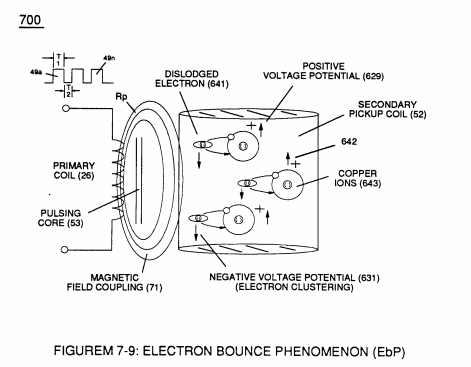
… Bifilar wound in equal length to optimize the electromagnetic field strength (FL) in equal electromagnetic intensity (FL1 = FL2) to encourage and promote "Electron Bounce" phenomenon (700) of Figure (7-9) while adjusting (programmable pulse wave-form) input signal Pulse-Frequency (49a xx 49n) to "tune-in" to the "dielectric property" (Re) of water (85) causing amp flow to be reduce to a minimum value …
-
"Electron Bounce" phenomenon (700) of Figure (7-9)
Transformer Action 5×
-
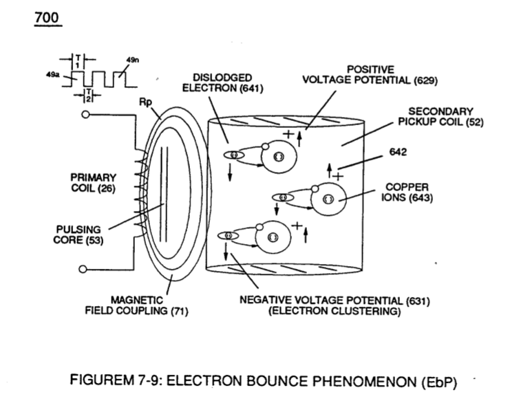
(L1) and (L2) are the inductances of each individual choke coil (56)(62) in series with Secondary Coil (52) Electrical Voltage Potential (700) of Figure (7-9) and being exposed to the same Voltage Transformer (26 - 53 - 52) magnetic field (Rp) with aiding fields,
-
… re (5-9) locks onto the electromagnetic fields of each energized choke coils (FL1/FL2) during Voltage Excitation (Vo -Vn) which, now, brings on and allows "Electron Bounce Phenomenon" (700) of Figure (7-9) to take place.
-
(700) of Figure (7-9)
-
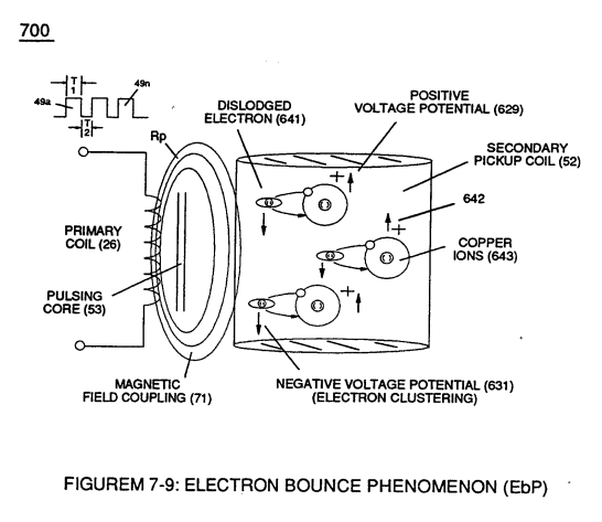
Note 1) The Electron Inhibiting Effect (631) of Figure (7-6) to cause "Electron Clustering" (Grouping/collecting negative charged particles at a given point) (700) of Figure (7-9) to produce ''Negative Voltage Potential" ( B- ) at one side of Water Gap (Cp) of Figure (7-8) is accomplished by low electrical power input (Tab 38) when Choke-Coil (62) of Figure (7-1) magnetic fiel …
-
"Electron Clustering" (Grouping/collecting negative charged particles at a given point) (700) of Figure (7-9)
Electron Bounce Phenomenon 6×
-
… he total inductance of Choke Coils (FL1 - FL2), (L1) and (L2) are the inductance of each individual choke coil (56)(62) in series with Secondary Coil (52) Electrical Voltage Potential (700) of Figure (7-9) and being exposed to the same Voltage Transformer (26 - 53 - 52) magnetic field (Rp) with aiding fields, (M) is the mutual inductance of choke coils (L1/L2) since Transformer Magnetic Field (Rp) is t …
-
... allowing, Voltage Bounce Phenomenon (700) of Figure (7-9) to be preformed.
-
(700) of Figure (7-9)
-
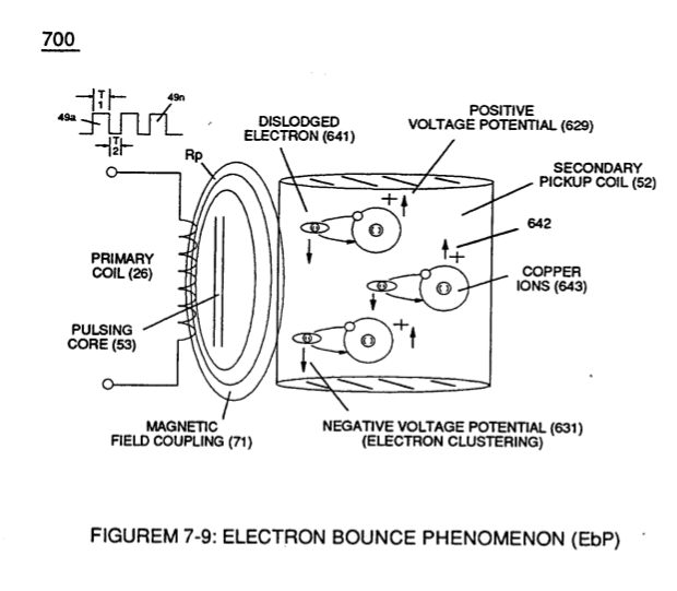
Magnetic Field Coupling (71) of Figure (7-9) entering into and passing through Secondary Coil-winding (52) of Figure (7-8) causes and produces copper ions (643a xxx 643n) (Positive Charged atoms 542a xxx 542n having missing electrons) when movi …
-
Sustaining and maintaining the resultant induced Voltage Potential (Vo - Vn) without "Electron Discharged" (inhibiting electron flow) through Choke Coil (62) while, at the same time, inhibiting (preventing) any additional or other electrons from entering into Secondary copper wire-zone (52) by way of Choke Coil (56) is herein called "Electron Bounce Phenomenon" (EbP), as illustrated in (700) of Figure (7-9).
-
(700) of Figure (7-9)
8-3 - Electrical Voltage-Pulse Wave-Transmission 2×
-
Opposite negative Voltage Pulse Train (67 - 602a xxx 602n) is similarly formed since "Electron Clustering Effect" (631) of Figure (7-9) produces a "Negative Electrical Voltage Intensity (67) in equal magnitude to the "Positive Electrical Voltage Intensity (66) during each/repetitious magnetic pulse-cycle (Rp/71). …
-
(631) of Figure (7-9)
Appendix B - Glossary of Applicaiton Notes 1×
-
Note 1) The Electron Inhibiting Effect (631) of Figure (7-6) to cause "Electron Clustering" (Grouping/collecting negative charged particles at a given point) (700) of Figure (7-9) to produce "Negative Voltage Potential" (B-) at one side of Water Gap (Cp) of Figure (7-8) is accomplished by low electrical power input (Tab 38) when Choke-Coil (62) of Figure (7-1) magnetic field ( …