(64) · also written as a run, 64a xxx 64n
Pulse Train
Also written incoming unipolar pulse train · Unipolar pulse train · incoming pulse train · Voltage Amplitude · Electrical Pulse Voltage amplitude · unipolar voltage wave-form · Unipolar Pulse-Train · pulse-train and 8 more
Where it is first named
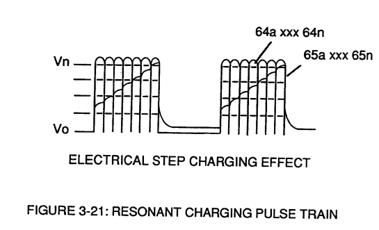
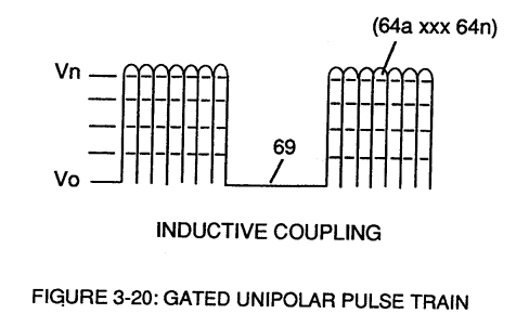
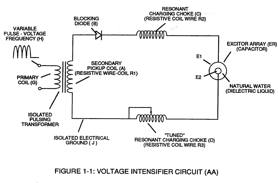
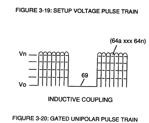
These controlled and variable pulse features are, now, translated to Resonant Charging pulse train (65a xxx 65n) of Figure (3-21) via Unipolar pulse train (64a xxx 64n) of Figure (3-20) during Resonant Action (160) of Figure (3-26) when signal coupling is applied across Resonant Cavity (170) of Figure (3-24) via positive voltage zone (66).
How it is written
- (64a xxx 64n) 15×
- (64) 3×
- (64a xxx T3 xxx 64n) 2× with (T3) Unipolar Pulse-Train
- (64a/64b - T3 - 64a/64b) 1× with (T3) Unipolar Pulse-Train
- (64b) 1×
- (Vo - 64a - 64b - 64c - Vn) 1× with (Vo) Applied Voltage Amplitude, (Vn) Voltage Potential
- (Vo - 64a - 64b- 64c - Vn) 1× with (Vo) Applied Voltage Amplitude, (Vn) Voltage Potential
- (Vo -64a-64b -64c - Vn) 1× with (Vo) Applied Voltage Amplitude, (Vn) Voltage Potential
64a xxx 64n is Meyer's shorthand for a run of the same thing: 64a is the first, 64n the last, and the x's stand for however many lie between. Every stage of the run is this one numeral. A pair before the letters, 583/602a, is a run of two things that go together, one of each per stage.
Drawings 86
-
Figure (3-21) · Voltage Amplitude Control Circuit (50)
-
Figure (3-20) · Voltage Intensifier Circuit (60)
-
Figure (3-21) · Voltage Intensifier Circuit (60)
-
Carries this number · Voltage Dynamics
-
Carries this number · Gas Processor
-
Carries this number · WFC 422DA - Illustrations
-
Carries this number · WFC 422DA - Illustrations
-
Carries this number · Electronic Circuit Design
-
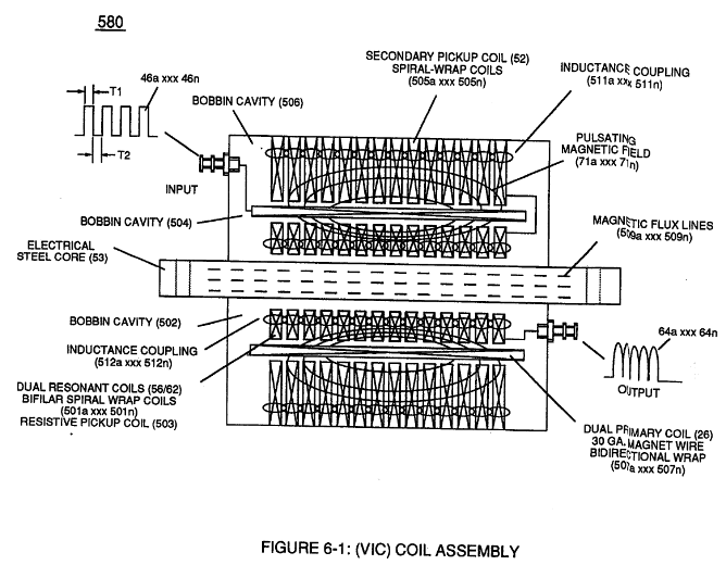
coil-structures (580) of Figure (6-1) · Voltage Intensifier Coil-Assembly
-
Voltage Intensifier Circuit (620) of Figure (7-1) · Instant Explosion of Water
-
(628) of Figure (7-7) · Instant Explosion of Water
-
(620) of Figure (7-1) · Instant Explosion of Water
-
(620) of Figure (7-1) · Resistance (Rs)
-
(614) of Figure (7-1) · Inductance (FL)
-
(580) of Figure (6-1) · Inductance (FL)
-
Inductor (614) of Figure (7-1) · Inductance (FL)
-
(614) of (7-1) · Inductance (FL)
-
Figure (7-1) · Capacitance (Cd)
-
(627) of Figure (7-7) · Inductance Reactance (Rs - Cd - FL)
-
(620) of Figure (7-1) · Inductance Reactance (Rs - Cd - FL)
-
(580) of Figure (6-1) · Multi-layer Coil
-
Choke-Coil (62) of Figure (7-1) · Transformer Action
-
Carries this number · WFC 426 - Illustrations
-
Carries this number · WFC 426 - Illustrations
-
Carries this number · 8-1 - Propagating "Resonant Action" By Voltage Tickling of State Space
-
Carries this number · 8-1 - Propagating "Resonant Action" By Voltage Tickling of State Space
-
(580) of Figure (6-1) (WFC memo 425) · 8-2 - Traveling Voltage Wave-Guides
-
(770 B) of Figure (8-1) · 8-4 - State Space (Sp)
-
(585) of Figure (8-1) · 8-4 - State Space (Sp)
-
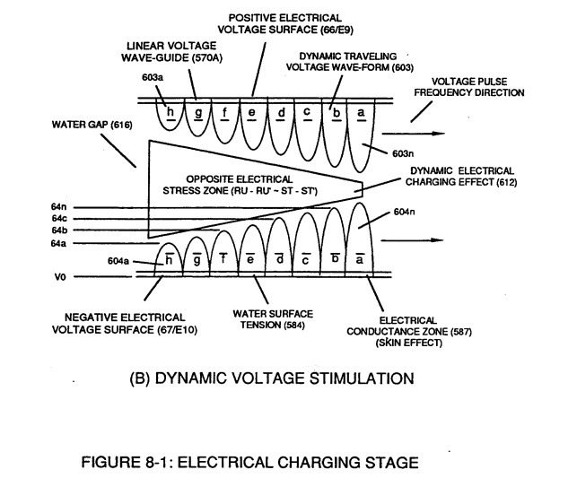
(612) of Figure (8-1) · 8-5 - Energy Vectoring (Ev)
-
Carries this number · 8-6 - VIC Voltage Sync-Pulse Circuit
-
(620) of Figure (7-1) · 8-6 - VIC Voltage Sync-Pulse Circuit
-
Carries this number · WFC 427 Illustrations
-
"Resonant Charging Choke" (56) of Figure (7-1) · Propagating Electrical Stress
-
Dynamic Electrical Charging Effect (612) of Figure (8-1) · Propagating Electrical Stress
-
(580) of Figure (6-1) · Voltage to Amp Differential Ratio
-
(620) of figure (7-1) · Voltage to Amp Differential Ratio
-
... establishing variable Dynamic Electrical Charging Effect (612). · Quartz Tube Configuration & Operational Parameters
-
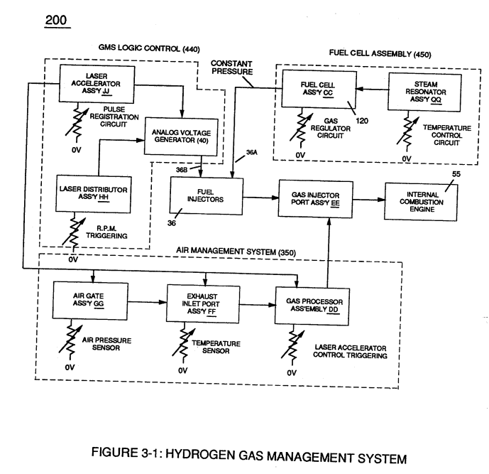
Figure (3-22) · Analog Voltage generator (40)
-
Figure (3-22) · Voltage Amplitude Control Circuit (50)
-
Figure (3-22) · Voltage Intensifier Circuit (60)
-
Figure (3-22) · Voltage Dynamics
-
Voltage Intensifier Circuit (60) of Figure (3-22) · Gas Processor
-
The figure it sits on · WFC 422DA - Illustrations
-
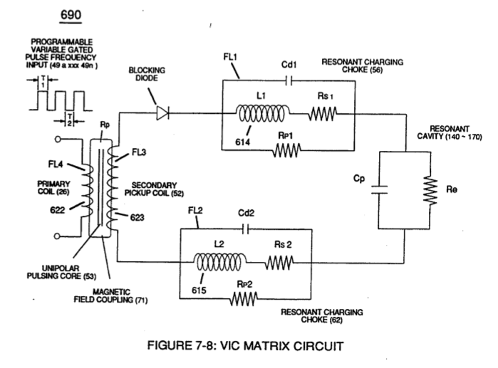
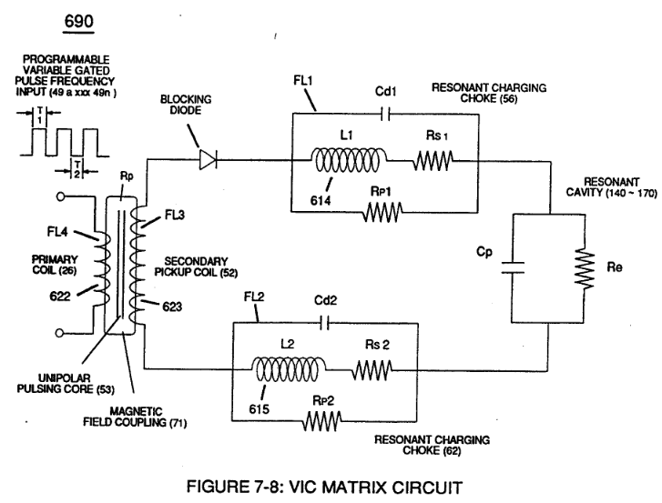
The figure it sits on · VIC Matrix Circuit
-
Voltage Intensifier Circuit (60) of Figure (3-22) · Instant Explosion of Water
-
(56/62) of Figure (3-22) · Instant Explosion of Water
-
(T2) of Figure (7-8) · Instant Explosion of Water
-
(56) of Figure (3-22) · Instant Explosion of Water
-
Figure (7-8) · Resistance (Rs)
-
(690) of Figure (7-8) · Resistance (Rs)
-
(690) of Figure (7-8) · Inductance (FL)
-
(690) of Figure (7-8) · Capacitance (Cd)
-
(690) of Figure (7-8) · Inductance Reactance (Rs - Cd - FL)
-
Figure (7-8) · Inductance Reactance (Rs - Cd - FL)
-
(690) of Figure (7-8) · Taper Resonant Capacitor (ERt)
-
690 of Figure 7-8 · Circuit Resistance
-
(52) of Figure (7-8) · Electron Bounce Phenomenon
-
(780A) Figure (8-2) · 8-2 - Traveling Voltage Wave-Guides
-
Figure (8-6) · 8-2 - Traveling Voltage Wave-Guides
-
(690) of Figure (7-8) · 8-2 - Traveling Voltage Wave-Guides
-
(770) of Figure(8-1) · 8-2 - Traveling Voltage Wave-Guides
-
Figure (8-2) · 8-2 - Traveling Voltage Wave-Guides
-
(770) of Figure (8-1) · 8-3 - Electrical Voltage-Pulse Wave-Transmission
-
(52) of Figure (7-8) · 8-3 - Electrical Voltage-Pulse Wave-Transmission
-
(Cp) of Figure (7-8) · 8-4 - State Space (Sp)
-
(770 A) of Figure (8-1) · 8-4 - State Space (Sp)
-
(780 B) of Figure (8-2) · 8-4 - State Space (Sp)
-
(780 A/B/C) of Figure (8-2) · 8-4 - State Space (Sp)
-
(770A) of Figure (8-1) · 8-5 - Energy Vectoring (Ev)
-
Clipped Voltage Wave-form (780C) of Figure (8-2) · 8-5 - Energy Vectoring (Ev)
-
The figure it sits on · 8-6 - VIC Voltage Sync-Pulse Circuit
-
(690) of Figure (7-8) · 8-6 - VIC Voltage Sync-Pulse Circuit
-
(Cp) of (7-8) · 8-6 - VIC Voltage Sync-Pulse Circuit
-
(820B) of Figure (8-6) · 8-7 - Application of Usage
-
(820C) of Figure (8-6) · 8-7 - Application of Usage
-
Figure (820A) of Figure (8-6) · 8-7 - Application of Usage
-
The figure it sits on · WFC 427 Illustrations
-
The figure it sits on · WFC 427 Illustrations
-
"Voltage Tickling of State Space" (770A) of Figure (8-1) · WFC Exhaust Air Reclaimer
-
"Voltage Tickling of State Space" (770B) of Figure (8-1) · WFC Exhaust Air Reclaimer
-
(690) of Figure (7-8) · Propagating Electrical Stress
-
Voltage Intensifier Circuit (60) of Figure (3-22) · Propagating Electrical Stress
-
(60) of Figure (3-22) · Propagating Electrical Stress
-
The figure it sits on · Quartz Tube Configuration & Operational Parameters
-
The figure it sits on · WFC 429 - Illustrations
Where it is named · 29
Voltage Intensifier Circuit (60) 6×
-
Unipolar pulse train (64a xxx 64n)
These controlled and variable pulse features are, now, translated to Resonant Charging pulse train (65a xxx 65n) of Figure (3-21) via Unipolar pulse train (64a xxx 64n) of Figure (3-20) during Resonant Action (160) of Figure (3-26) when signal coupling is applied across Resonant Cavity (170) of Figure (3-24) via positive voltage zone (66).
-
pulse train (64a xxx 64n)
...allowing magnetic fields of both inductor coils (56/57) to collapse ... forming pulse train (64a xxx 64n).
-
incoming unipolar pulse train (64a xxx 64n)
During resonant interaction, the incoming unipolar pulse train (64a xxx 64n) of Figure (320) as to Figure (3-21) produces a step charging voltage effect across excitor-array (66/67) (57) as so illustrated in Figure (3-21).
-
voltage-pulse (64)
Once voltage-pulse (64) is terminated or switch-off, voltage potential returns to "ground-state" (61) or near ground-state (diode 55 maintains voltage charged across capacitor 57) to start the voltage deflection process over again as pulse train (64a xxx 64n) continues to be duplicated.
-
Once voltage-pulse (64) is terminated or switch-off, voltage potential returns to "ground-state" (61) or near ground-state (diode 55 maintains voltage charged across capacitor 57) to start the voltage deflection process over again as pulse train (64a xxx 64n) continues to be duplicated.
-
pulse train (64a xxx 64n)
"Voltage intensity or level across excitor array (57) can exceed 20,000 volts due to circuit (60) interaction and is directly related to pulse train (64a xxx 64n) variable amplitude input.
Resonant Action 3×
-
incoming pulse train (64a xxx 64n)
In cases where applied voltage amplitude is to remain constant while promoting Resonant Action during control-state, incoming pulse train (64a xxx 64n) is varied independent of voltage amplitude to attenuate voltage intensity (66/67) which, in turn, effects gas production.
-
pulse-train (64a xxx 64n)
In other applications, Voltage amplitude (66/67) in direct relationship to pulse-train (64a xxx 64n) may be varied together in a progressive manner to further control gas production. Or pulse-train (64a xxx 64n) can remain constant while voltage amplitude is varied.
-
In other applications, Voltage amplitude (66/67) in direct relationship to pulse-train (64a xxx 64n) may be varied together in a progressive manner to further control gas production. Or pulse-train (64a xxx 64n) can remain constant while voltage amplitude is varied.
Water Fuel Injector (Taper Resonant Cavity Chamber) 1×
-
electromagnetic field (63/64)
The "Plus Factor" is that induce external electromagnetic field (63/64) across Resonant coil-Tap (67) increases voltage intensity (voltage potential) still further rather than diminishes peak voltage potential due to resistive valve of the stainless steel wire.
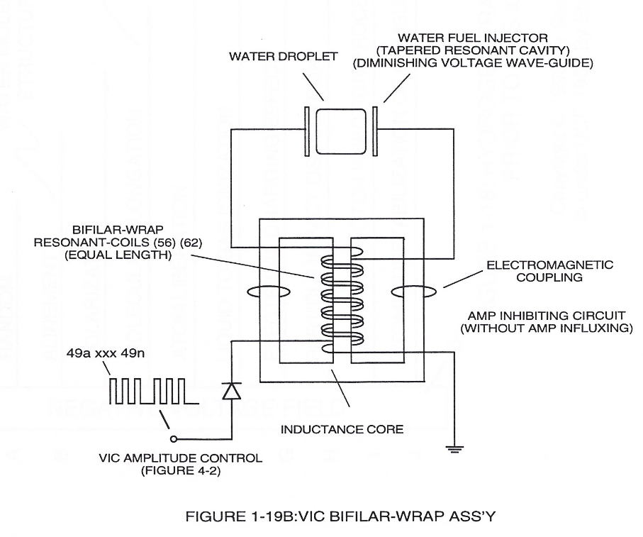
Water Fuel Injector 3×
-
... dielectric value of water being 78.54 since water molecule (85) oxygen atom "L" orbit (76) occupies the maximum allowance eight electrons (79a xxx 79n), calibrated gated unipolar pulse train (64a xxx 64n) of Figure (3-20) is outputted from resonant choke (56) and electrically transmitted to positive outer conical surface (E9);
-
Together, parallel sides (E9 / El0) not only functions as a "voltage wave-guide" (570) but, also, acts and performs as a "voltage intensifier circuit" when applied gated pulse-frequency (64a xxx 64n) travels the length of conical cavity (570) toward exit port (32).
-
Activation point (E9a) exposes water flow (85) to voltage wave-form (64) of Figure (6-1) to begin water-to-energy conversion process (100);
Instant Explosion of Water 7×
-
VIC Voltage Enhancement Circuit (VIC - VB) (620) of Figure (7-1) incorporates the use of stainless steel wire-wrap coils (614/615) to accomplish the formation of unipolar gated pulse-wave (64a xxx T3 xxx 64n) without experiencing "signal distortion" or "signal degradation" (preventing transformer ringing during signal propagation) as elevated voltage levels ( - xx Vc- xx Vd - xx Vn) while allowing the red …
-
unipolar pulse wave-form (64a - 64b)
... Diode (55) being placed between Secondary Pickup Coil (52) and Resonant Charging Choke (56) to act as an electronic switch in open-position during pulse off-time (T2) of Figure (7-8) while preventing electron flow in reverse direction when Inductor (L1) collapsing electromagnetic field (FL1) produces another unipolar pulse wave-form (64a - 64b).
-
unipolar voltage wave-form (64a xxx 64n)
... producing unipolar voltage wave-form (64a xxx 64n) during repeated pulse-signal (46a xxx 46n) on-time (T1a xxx T1n)
-
... allowing the formation of an gated pulse-frequency pulse-train (64a/64b - T3 - 64a/64b) when pulse off-time (T3) is greater than time-period (T2)
-
Unipolar Pulse-Train (64a xxx T3 xxx 64n)
... input-signal (49a xxx 49n) being a Pulse-Train where (T2) pulse offtime (T2) is adjusted to allow Unipolar Pulse-Train (64a xxx T3 xxx 64n)
-
Voltage-wave signal (64a xxx 64n)
... outputting Voltage-wave signal (64a xxx 64n) being a pulse-frequency doubler due to Inductance Reactance (FL) of Inductor Coil (56) of Figure (3-22) when collapsing magnetic field (FL) of Figure (7-3b) re-cuts coil-wrap (Ll) during each pulse off-time (T2)
-
unipolar voltage wave-form (64b)
... producing a second unipolar voltage wave-form (64b) during the rise and fall of magnetic field (71), as further illustrated in (620) of Figure (7-1)
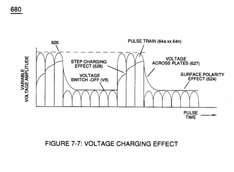
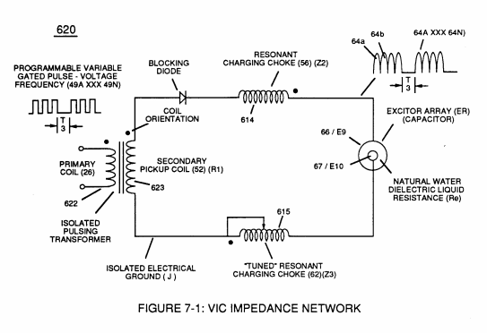
Inductance (FL) 1×
-
pulse-forming network (64a xxx 64n)
… pulsing transforms Inductor (614) of Figure (7-1) / Capacitor (E9/E10) of Figure (7-11) LC circuit of Figure (7-2) into an Resonant Charging Choke (614) which steps up an unipolar oscillation of an given charging frequency with the effective capacitance of a pulse-forming network (64a xxx 64n) of Figure (7-1) as to (600) of Figure (6-3) in order to charge Voltage Zones (E9/E10) to a higher potential beyond applied voltage input
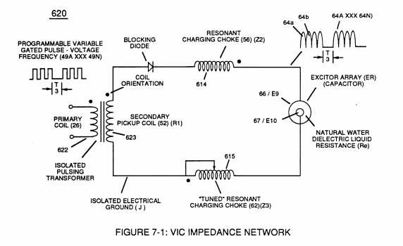
Taper Resonant Capacitor (ERt) 1×
-
Stainless steel T304 material is used to form Electrical Voltage-Plates (EIIE2) which do "not" chemically interact (chemically inert) (Lab tested less than .0001/year decomposition rate) with liberated water gases (hydrogen _86, oxygen _87, and non-combustible gases W being exposed to an high intensity voltage pulse-field (64a xxx 64n) with negligible amp flow.
Mode of Operability 1×
-
Unipolar Wave-forms (64a xxx 64n)
Pulse Off-time (T2) of Figure (7-8) as to (620) of Figure (7-1) is adjusted to compensate for the rise and fall of magnetic coupling field (71) to produce applied Unipolar Wave-forms (64a xxx 64n) entering into Wave-guides (35a/35b/35c).
8-1 - Propagating "Resonant Action" By Voltage Tickling of State Space 1×
-
Voltage Pulse-Wave (64)
Static variables condition is established when the resultant gas pressure is held constant with the never-changing static electrical stress of opposite polarity of Voltage Pulse-Wave (64) of Figure (3-20) of WFC memo 422DA.
8-2 - Traveling Voltage Wave-Guides 2×
-
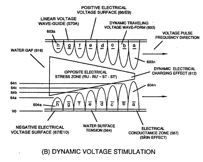
… 6-1) (WFC memo 425) ability to inhibit amp "influxing" (Electron Bounce Phenomenon EbP) during pulsing operations (49a xx 49n) allows voltage amplitude of pulse-frequency potential (T1a xxxT1n) as to (Vo -64a-64b -64c - Vn) of (780A) Figure (8-2) to be applied across cross-sectional circular-ring water bath (85) (donut shape) to cause Voltage Wave-Form (57) of Figure (6-2) to travel the entire longitudinal length of wat …
-
voltage amplitude potential (Vo - 64a - 64b - 64c - Vn)
... thereby, maintaining voltage amplitude potential (Vo - 64a - 64b - 64c - Vn) of Figure (8-6) without experiencing amp arc-over across Water-Gap (616) in any appreciable amount
8-3 - Electrical Voltage-Pulse Wave-Transmission 1×
-
Electrical Pulse Voltage amplitude (Vo - 64a - 64b- 64c - Vn)
Electrical Voltage-Pulse Wave-Transmission (583a xxx 583n), now formed, occurs along Electrical Conductance Zone (587) since applied Electrical Pulse Voltage amplitude (Vo - 64a - 64b- 64c - Vn) is time responsive (T1/T2a - T3 – T1/T2n) to incoming gated Voltage Pulse Frequency (49a xxx - 1'3 - xxx 49n).
8-4 - State Space (Sp) 1×
-
Voltage Amplitude (xx 64a - 64b - 64c - Vn)
In terms of Particle Oscillation (Poe) as a Energy-Generator (EGpo), if Voltage Arc Line (Val) length is extended while Voltage Amplitude (xx 64a - 64b - 64c - Vn) is adjusted to higher Voltage Peak-Potential (Vpp) then greater atomic interaction (585) of Figure (8-1) (see WFC memo 424 titled Atomic Energy Balance of Water, once again) occurs when particle osci …
Quartz Tube Configuration & Operational Parameters 1×
-
Voltage Amplitude (64a - 64b - 64c - 64n)
The resultant Flex-Density (Fd) of the hydrogen atom(s) is, now, directly related to applied Voltage Amplitude (64a - 64b - 64c - 64n) of Figure (8-2A) which directly determines the Field Strength (Fs) of Static Electrical Charging Effect (Sece)(585).