(26)
Primary Coil
Also written Voltage Transformer · Primary Coil-Winding · Pulsing transformer · transformer coils · transformer coil · VIC Transformer · Inductor Coils
Where it is first named
Voltage valves or levels (22a xxx 22n) simply controls the applied voltage potential across Resonant Cavity Assembly (120) of Figure (3-22) through voltage amplitude control circuit (50) of Figure (3-5) which is is electrically linked to primary coil (26) of Figure (3-22) of Voltage Intensifier Circuit (60) of Figure (3-5).
How it is written
- (26) 23×
- (26/52) 4× with (52) Secondary Coil
- (26 - 53 - 52) 2× with (53) Pulsing Core, (52) Secondary Coil
- (26 - 52 - 56 - 62) 1× with (52) Secondary Coil, (56) Resonant Charging Choke, (62) Resonant Charging Chokes
Drawings 98
-
Stanley A. Meyer Page27 of 28 · WFC 417 — WFC 417
-
Carries this number · Magnetic Field Enhancement
-
Carries this number · Magnetic Field Enhancement
-
Figure (3-22) · Analog Voltage generator (40)
-
Figure (3-22) · Voltage Amplitude Control Circuit (50)
-
Figure (3-26) · Voltage Intensifier Circuit (60)
-
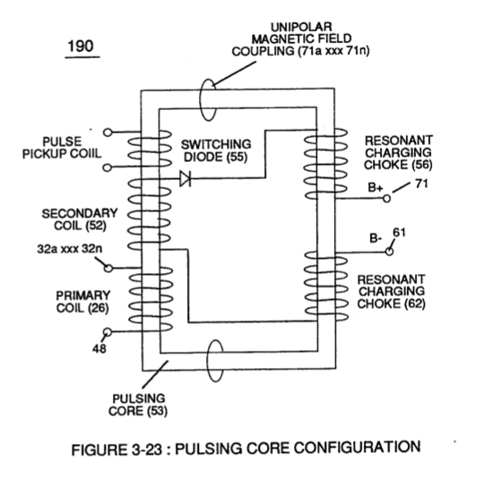
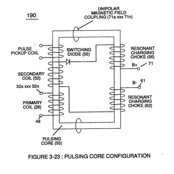
Figure (3-23) · Voltage Intensifier Circuit (60)
-
Figure (3-22) · Voltage Intensifier Circuit (60)
-
Figure (3-22) · Voltage Dynamics
-
Figure (3-23) · Voltage Dynamics
-
Figure (3-26) · Electrically Charged Water Molecule
-
Voltage Intensifier Circuit (60) of Figure (3-22) · Gas Processor
-
(270) of Figure (3-34) · Gas Processor
-
Carries this number · WFC 422DA - Illustrations
-
Carries this number · WFC 422DA - Illustrations
-
Carries this number · WFC 422DA - Illustrations
-
Carries this number · WFC 422DA - Illustrations
-
Carries this number · Electronic Circuit Design
-
Carries this number · Electronic Circuit Design
-
Carries this number · Electronic Circuit Design
-
Figure (25) · Water Fuel Injector (Taper Resonant Cavity Chamber)
-
Carries this number · Cover Page
-
(160) of Figure (3-26) · Water Fuel Injection System - Page 1
-
(85) of Figure (3-26) · In Application of Usage
-
(160) of Figure (3-26) · In Application of Usage
-
(270) of (3-34) · In Application of Usage
-
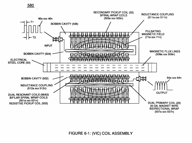
coil-structures (580) of Figure (6-1) · Voltage Intensifier Coil-Assembly
-
(190) of Figure (3-23) · Tri - Coil Construction
-
Carries this number · VIC Matrix Circuit
-
Voltage Intensifier Circuit (60) of Figure (3-22) · Instant Explosion of Water
-
Voltage Intensifier Circuit (620) of Figure (7-1) · Instant Explosion of Water
-
(56/62) of Figure (3-22) · Instant Explosion of Water
-
(700) of Figure (7-9) · Instant Explosion of Water
-
(T2) of Figure (7-8) · Instant Explosion of Water
-
(56) of Figure (3-22) · Instant Explosion of Water
-
(620) of Figure (7-1) · Instant Explosion of Water
-
Figure (7-8) · Resistance (Rs)
-
(85) of Figure (3-26) · Resistance (Rs)
-
(620) of Figure (7-1) · Resistance (Rs)
-
(690) of Figure (7-8) · Resistance (Rs)
-
(614) of Figure (7-1) · Inductance (FL)
-
(580) of Figure (6-1) · Inductance (FL)
-
Inductor (614) of Figure (7-1) · Inductance (FL)
-
(614) of (7-1) · Inductance (FL)
-
Figure (7-1) · Capacitance (Cd)
-
(690) of Figure (7-8) · Capacitance (Cd)
-
(690) of Figure (7-8) · Inductance Reactance (Rs - Cd - FL)
-
"Electron Bounce" phenomenon (700) of Figure (7-9) · Inductance Reactance (Rs - Cd - FL)
-
Inductance Pulsing-Core (190) of Figure (3-23) · Inductance Reactance (Rs - Cd - FL)
-
Figure (7-8) · Inductance Reactance (Rs - Cd - FL)
-
(620) of Figure (7-1) · Inductance Reactance (Rs - Cd - FL)
-
(580) of Figure (6-1) · Multi-layer Coil
-
(690) of Figure (7-8) · Taper Resonant Capacitor (ERt)
-
690 of Figure 7-8 · Circuit Resistance
-
The turns ratio of the VIC Transformer (26/52) is determined by the following equation: · Transformer Action
-
(L1) and L2) are the inductances of each individual transformer coils (26)(52), · Transformer Action
-
"Electron Clustering" (Grouping/collecting negative charged particles at a given point) (700) of Figure (7-9) · Transformer Action
-
Choke-Coil (62) of Figure (7-1) · Transformer Action
-
Carries this number · Electron Bounce Phenomenon
-
(52) of Figure (7-8) · Electron Bounce Phenomenon
-
(700) of Figure (7-9) · Electron Bounce Phenomenon
-
Carries this number · WFC 426 - Illustrations
-
Carries this number · WFC 426 - Illustrations
-
Carries this number · WFC 426 - Illustrations
-
(580) of Figure (6-1) (WFC memo 425) · 8-2 - Traveling Voltage Wave-Guides
-
(690) of Figure (7-8) · 8-2 - Traveling Voltage Wave-Guides
-
(631) of Figure (7-9) · 8-3 - Electrical Voltage-Pulse Wave-Transmission
-
(52) of Figure (7-8) · 8-3 - Electrical Voltage-Pulse Wave-Transmission
-
(Cp) of Figure (7-8) · 8-4 - State Space (Sp)
-
(620) of Figure (7-1) · 8-6 - VIC Voltage Sync-Pulse Circuit
-
(690) of Figure (7-8) · 8-6 - VIC Voltage Sync-Pulse Circuit
-
(840) of Figure (8-10) · 8-6 - VIC Voltage Sync-Pulse Circuit
-
(Cp) of (7-8) · 8-6 - VIC Voltage Sync-Pulse Circuit
-
Carries this number · WFC 427 Illustrations
-
Carries this number · WFC Exhaust Air Reclaimer
-
(690) of Figure (7-8) · Propagating Electrical Stress
-
Figure (3-34) · Propagating Electrical Stress
-
Voltage Intensifier Circuit (60) of Figure (3-22) · Propagating Electrical Stress
-
(160) of Figure (3-26) · Propagating Electrical Stress
-
(60) of Figure (3-22) · Propagating Electrical Stress
-
(580) of Figure (6-1) · Voltage to Amp Differential Ratio
-
blocking diode (55) of Figure (3-34) · Voltage to Amp Differential Ratio
-
(620) of figure (7-1) · Voltage to Amp Differential Ratio
-
Original Content Image · WFC - Resonant Cavity Assembly
-
Figure (3-21) · Voltage Amplitude Control Circuit (50)
-
Figure (3-18) · Cell Driver Circuit (90)
-
Figure (3-19) · Cell Driver Circuit (90)
-
Figure (3-19) · Voltage Intensifier Circuit (60)
-
Figure (3-21) · Voltage Intensifier Circuit (60)
-
The figure it sits on · Voltage Dynamics
-
The figure it sits on · Gas Processor
-
The figure it sits on · WFC 422DA - Illustrations
-
The figure it sits on · WFC 422DA - Illustrations
-
The figure it sits on · WFC 422DA - Illustrations
-
(690) of Figure (7-8) · Inductance (FL)
-
The figure it sits on · 8-1 - Propagating "Resonant Action" By Voltage Tickling of State Space
-
"Resonant Charging Choke" (56) of Figure (7-1) · Propagating Electrical Stress
-
The figure it sits on · WFC 429 - Illustrations
Where it is named · 30
Analog Voltage generator (40) 1×
-
primary coil (26)
Voltage valves or levels (22a xxx 22n) simply controls the applied voltage potential across Resonant Cavity Assembly (120) of Figure (3-22) through voltage amplitude control circuit (50) of Figure (3-5) which is is electrically linked to primary coil (26) of Figure (3-22) of Voltage Intensifier Circuit (60) of Figure (3-5).
Voltage Amplitude Control Circuit (50) 2×
-
primary coil (26)
First, regulates car battery electrical voltage potential (32) of Figure (3-15) being applied to primary coil (26) of Figure (3-21); and secondly, regulates gas pressure of Fuel Cell (120) of Figure (3-22), as graphically depicted in Figure (3-15).
-
primary coil (26)
Variable voltage range (32a xxx 32n) from one (1) up to twelve (12) volts (regulating battery voltage) is applied across primary coil (26) of Voltage Intensifier Circuit (60) of Figure (3-21).
Cell Driver Circuit (90) 2×
-
primary coil (26)
In either case, the resultant or varied pulse train (47a xxx 47n) (calibration of 44a xxx 44n) becomes incoming gated pulse signal (48) of figure (3-5) to cell driver circuit (90) of Figure (3-5) which performs a switching function by switching "off' and "on" electric ground being applied to opposite side (48) of primary coil (26) of Figure (3-19).
-
primary coil (26)
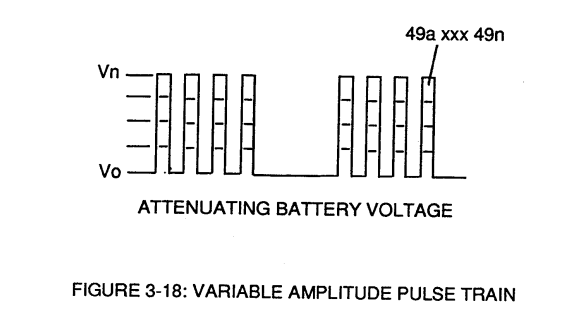
The resultant pulse wave form (49a xxx 49n) of Figure (3-18) superimposed onto primary coil (26) is exact duplicate of proportional pulse train (47a xxx 47n).
Voltage Intensifier Circuit (60) 5×
-
primary coil (26)
By integrating and joining together variable voltage amplitude control signal (318 xxx 32n) of Figure (3-15) with variable controlled switch-gate (49a xxx 49n) of Figure (3-18) across primary coil (26) of Figure (3-22),
-
Primary Coil (26)
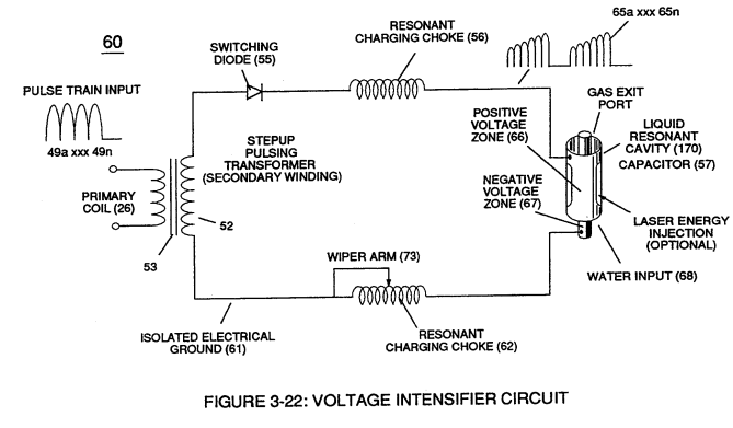
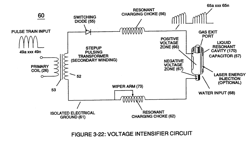
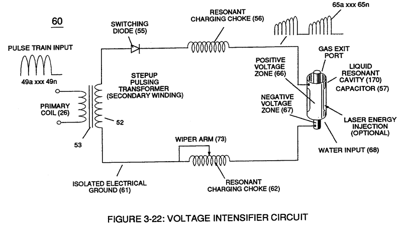
Negative electrical voltage potential (61) of pulse wave (65a xxx 65n) of Figure (3-21) is simultaneously applied to negative voltage zone (67) via Resonant Charging Choke (62) of Figure (3-22) which is electrically linked to opposite end of Primary Coil (26).
-
primary coil (26)
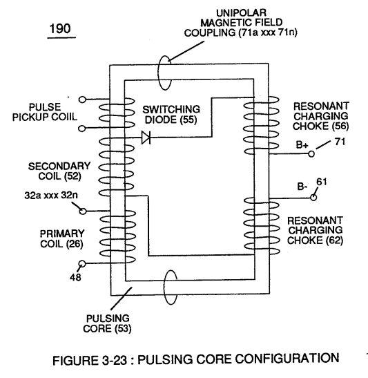
The resultant signal coupling ( 65a xx 65n ) of Figure (3-21) is accomplished since primary coil (26), pulsing core (53), secondary coil (52), switching diode (55), resonant charging choke (56), resonant cavity assembly (170), natural water (68), and variable resonant charging choke (62) forms Voltage Intensifier Circuit (60) of Figure (3-22), as illustrated in Figure (3-22) as to Figure (3-23).
-
Pulsing transformer (26/52)
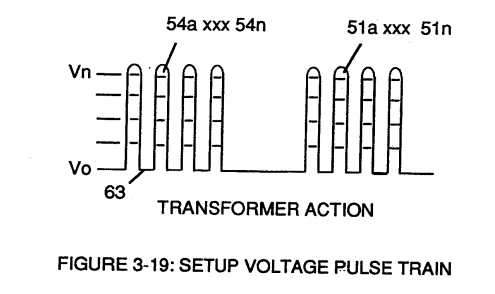
Pulsing transformer (26/52) of Figure (3-22) steps up voltage amplitude or voltage potential (Vo xxx Vn) of Figure (3-19) during pulsing operations.
-
Primary coil (26)
Primary coil (26) is electrically isolated (no electrical connection between primary 26 and secondary coil) to form Voltage Intensifier Circuit (60) of Figure (3-22).
Tri - Coil Construction 1×
-
Primary Coil (26)
Primary Coil (26) (typically .030 Ga.) film coated magnet wire is longitudinal wrapped in space relationship on top of and layered bidirectional (507a xxx 507n) across spiral-wrap coils (501a xxx 50 In) to complete bobbin cavity (504).
Transformer Action 13×
-
… eel laminations step up applied Voltage (49) when Magnetic Field Coupling (71) of Figure (7-8) cross over to Secondary Pickup Coil-winding (52) which has more turns of wire than Primary Coil- winding (26) by way of "Eddy" currents that induce magnetic flux lines of forces (71a xxx 71n) emanating away from magnetic core material (53) and caused by Primary Coil (26) being electrically energized during p …
-
Primary Coil (26)
… ns of wire than Primary Coil- winding (26) by way of "Eddy" currents that induce magnetic flux lines of forces (71a xxx 71n) emanating away from magnetic core material (53) and caused by Primary Coil (26) being electrically energized during pulsing operations (T1a xx T1n), as illustrated in (690) of Figure (7-8).
-
Primary Coil-Winding (26)
(Ip) is the amount of current flow in the Primary Coil-Winding (26) when electrically "energized" during pulsing operations (49a xxx 49n - T3 - 49a xxx 49a).
-
VIC Transformer (26/52)
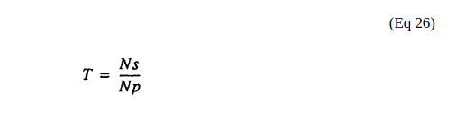
The turns ratio of the VIC Transformer (26/52) is determined by the following equation:
-
Primary Coil (26)
(Np) is the number of turns of the Primary Coil (26) wire-wrapped about spool cavity (504)
-
primary coil (26)
(1'2) is the sum of the magnetic field strength (FL4) of the primary coil (26) and the induced magnetic field (FL3) of the Secondary Pickup Coil (52) during each pulse cycle (T1) in direct relationship to repetitive pulse cycling (T1a xxx T1n) and both magnetic fields (FL3/FL4) interacting, and is expressed in the following equation:
-
Primary coil (26)
(La) is the total inductance of Primary coil (26) and Secondary coil (52) with fields aiding Coupling Inductance (Rp) between the Primary coil (26) and Secondary Coil (52) is further extrapolated in the following equation:
-
Primary coil (26)
(La) is the total inductance of Primary coil (26) and Secondary coil (52) with fields aiding Coupling Inductance (Rp) between the Primary coil (26) and Secondary Coil (52) is further extrapolated in the following equation:
-
(L1) and L2) are the inductances of each individual transformer coils (26)(52),
-
(M) is the mutual inductance of each transformer coil (26/52) being in parallel relationship with fields aiding Coupling Inductance (Rp1) and (Rp2) in (690) of Figure (7-8) is further expressed in the following equation:
-
Voltage Transformer (26 - 53 - 52)
(L1) and (L2) are the inductances of each individual choke coil (56)(62) in series with Secondary Coil (52) Electrical Voltage Potential (700) of Figure (7-9) and being exposed to the same Voltage Transformer (26 - 53 - 52) magnetic field (Rp) with aiding fields,
-
Inductor Coils (26 - 52 - 56 - 62)
VIC Coil Assembly (580) of Figure (6-1) as to (690) of Figure (7-8) in reference to Schematic Circuit (620) of Figure (7-1) is constructed in such a way as to rotate and position Inductor Coils (26 - 52 - 56 - 62) to be of the same electromagnetic polarity orientation, indicator mark (e)

Electron Bounce Phenomenon 5×
-
Primary coil (26)
Where, (M) is the mutual inductance expressed in the same units as (La), (La) is the total inductance of Primary coil (26) and Secondary coil (52) with fields aiding.
-
Primary coil (26)
Coupling Inductance (Rp) between the Primary coil (26) and Secondary Coil (52) is further extrapolated in the following equation: Where, (Lt) is the total inductance, (L1) and L2) are the inductance of each individual transformer coils (26)(52), (M) is the mutual inductance of each transformer coil (26/52) being in parallel relationship with fields aiding.
-
transformer coils (26)
Coupling Inductance (Rp) between the Primary coil (26) and Secondary Coil (52) is further extrapolated in the following equation: Where, (Lt) is the total inductance, (L1) and L2) are the inductance of each individual transformer coils (26)(52), (M) is the mutual inductance of each transformer coil (26/52) being in parallel relationship with fields aiding.
-
transformer coil (26/52)
Coupling Inductance (Rp) between the Primary coil (26) and Secondary Coil (52) is further extrapolated in the following equation: Where, (Lt) is the total inductance, (L1) and L2) are the inductance of each individual transformer coils (26)(52), (M) is the mutual inductance of each transformer coil (26/52) being in parallel relationship with fields aiding.
-
Voltage Transformer (26 - 53 - 52)
… (L2) are the inductance of each individual choke coil (56)(62) in series with Secondary Coil (52) Electrical Voltage Potential (700) of Figure (7-9) and being exposed to the same Voltage Transformer (26 - 53 - 52) magnetic field (Rp) with aiding fields, (M) is the mutual inductance of choke coils (L1/L2) since Transformer Magnetic Field (Rp) is the excitation External Magnetic Field (Rp1/Rp2) by way of Unipola …
Voltage Amplitude Switch-Off 1×
-
Primary Coil (26)
Switching the member of Secondary Coil-Array (505a xxx 505n) maximizes electrical power transfer from Primary Coil (26) to Secondary Coil (52) by keeping Voltage Amplitude of Pulse-train (49a xx 49n - T3 - 49a xxx 49n) constant.