(L1)
Inductor
Also written Lengthening Inductor · Inductors · Inductance Field · Inductor Cores · choke coils · Inductance
Where it is first named
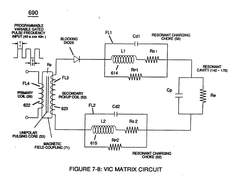
... Diode (55) being placed between Secondary Pickup Coil (52) and Resonant Charging Choke (56) to act as an electronic switch in open-position during pulse off-time (T2) of Figure (7-8) while preventing electron flow in reverse direction when Inductor (L1) collapsing electromagnetic field (FL1) produces another unipolar pulse wave-form (64a - 64b).
How it is written
- (L1/L2) 11× with (L2) Inductors
- (L1) 6×
- (L1-L2) 2× with (L2) Inductors
- (L1-FL1) 1× with (FL1) Distributed Inductance
Drawings 40
-
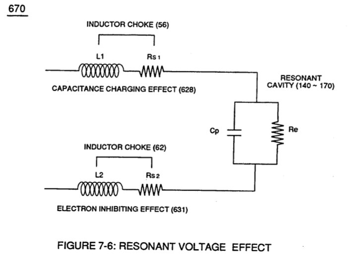
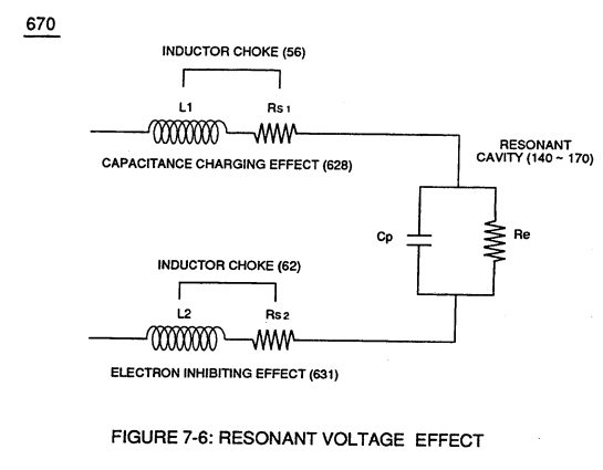
Inductors (L1-L2) of Figure (7-6) · Inductance Reactance (Rs - Cd - FL)
-
(L1) and L2) are the inductances of each individual transformer coils (26)(52), · Transformer Action
-
coil-structures (580) of Figure (6-1) · Voltage Intensifier Coil-Assembly
-
The figure it sits on · VIC Matrix Circuit
-
(700) of Figure (7-9) · Instant Explosion of Water
-
(T2) of Figure (7-8) · Instant Explosion of Water
-
Figure (7-8) · Resistance (Rs)
-
(690) of Figure (7-8) · Resistance (Rs)
-
(630) of Figure (7-2) · Inductance (FL)
-
(580) of Figure (6-1) · Inductance (FL)
-
(670) of Figure (7-6) · Inductance (FL)
-
(690) of Figure (7-8) · Inductance (FL)
-
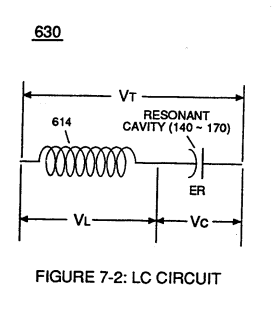
LC circuit of Figure (7-2) · Inductance (FL)
-
(670) of Figure (7-6) · Capacitance (Cd)
-
(690) of Figure (7-8) · Capacitance (Cd)
-
(690) of Figure (7-8) · Inductance Reactance (Rs - Cd - FL)
-
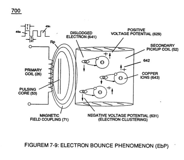
"Electron Bounce" phenomenon (700) of Figure (7-9) · Inductance Reactance (Rs - Cd - FL)
-
Figure (7-8) · Inductance Reactance (Rs - Cd - FL)
-
(580) of Figure (6-1) · Multi-layer Coil
-
The figure it sits on · Taper Resonant Capacitor (ERt)
-
(690) of Figure (7-8) · Taper Resonant Capacitor (ERt)
-
Resonant Capacitor (140 -170) of Figure (7-6) · Capacitance Reactance
-
Capacitor (ER) of Figure (7-2) · Capacitance Reactance
-
690 of Figure 7-8 · Circuit Resistance
-
Resonant Voltage Effect (670) of Figure (7-6) · Transformer Action
-
"Electron Clustering" (Grouping/collecting negative charged particles at a given point) (700) of Figure (7-9) · Transformer Action
-
(52) of Figure (7-8) · Electron Bounce Phenomenon
-
(700) of Figure (7-9) · Electron Bounce Phenomenon
-
The figure it sits on · WFC 426 - Illustrations
-
The figure it sits on · WFC 426 - Illustrations
-
(580) of Figure (6-1) (WFC memo 425) · 8-2 - Traveling Voltage Wave-Guides
-
(690) of Figure (7-8) · 8-2 - Traveling Voltage Wave-Guides
-
(631) of Figure (7-9) · 8-3 - Electrical Voltage-Pulse Wave-Transmission
-
(52) of Figure (7-8) · 8-3 - Electrical Voltage-Pulse Wave-Transmission
-
(Cp) of Figure (7-8) · 8-4 - State Space (Sp)
-
(690) of Figure (7-8) · 8-6 - VIC Voltage Sync-Pulse Circuit
-
(Cp) of (7-8) · 8-6 - VIC Voltage Sync-Pulse Circuit
-
(690) of Figure (7-8) · Propagating Electrical Stress
-
(580) of Figure (6-1) · Voltage to Amp Differential Ratio
-
The figure it sits on · WFC 429 - Illustrations
Where it is named · 20
Instant Explosion of Water 1×
-
Inductor (L1)
... Diode (55) being placed between Secondary Pickup Coil (52) and Resonant Charging Choke (56) to act as an electronic switch in open-position during pulse off-time (T2) of Figure (7-8) while preventing electron flow in reverse direction when Inductor (L1) collapsing electromagnetic field (FL1) produces another unipolar pulse wave-form (64a - 64b).
Inductance Reactance (Rs - Cd - FL) 6×
-
Inductors (L1-L2)
Inductance Reactance not only increases voltage across water-capacitor (ER) beyond applied Voltage Potential (626) of Figure (7-7) but, also, establishes "Impedance Field" (FL) across Inductors (L1-L2) of Figure (7-6) which acts and performs as Resonant Charging Chokes (614/615) of Figure (7-1) once placed on opposite side of capacitor (ER) forming Resonant voltage Effect Circuit (670) of Figure (7 …
-
Inductance Field (L1-FL1)
Inductance Field (L1-FL1) performs "Capacitance Charging Effect" (628);
-
Inductors (L1/L2)
… ic coupling field (Rp) of Figure (7-8) transmitted by way of Inductance Pulsing-Core (190) of Figure (3-23) as to VIC Coil Assembly (580) of Figure (6-1) enters into and passes through both Inductors (L1/L2) simultaneously and offers not only further electron-flow restriction (Rp1/Rp2) to both Inductor Chokes (56/62) but automatically increases voltage potential (xxx V g xxx Vh xxx Vn) of opposite voltag …
-
Inductor Cores (L1/L2)
... overcoming any potential loss of pulse signal due to resistive interaction (Rsl/Rs2) of either or both Inductor Cores (L1/L2) wire-material to the formation of Inductance Fields (FL1/FL2) during reoccurring pulse on-time (T1a xxx T1n).
-
Electron Inhibiting Effect (631) in direct relationship to Voltage Enhancement Effect (528) is accomplished since stainless steel 430F/FR wire-material is "Electromagnetic Inductive" to incoming electromagnetic flux-lines (71a xxx 71n) (Rp) without (s/s) inductor-wire-coil (L1/L2) becoming permanently magnetized
In-Line Circuit Components 3×
-
Lengthening Inductor (L1/L2)
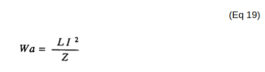
Lengthening Inductor (L1/L2) lengths applies an even higher Voltage Potential (66/67) across Resonant Capacitor (140 -170) (ER) since Inductance Reactance "Stores" Energy and, is expressed by:
-
Inductor (L1/L2)
Inductor (Ll) acts and performs in like manner to Inductor (L2) since both Inductor (L1/L2) are physically the same size and shape.
Capacitance Reactance 3×
-
Inductance (L1/L2)
Capacitance Reactance is determined by the insulation resistance (Rs+Re) and Inductance (L1/L2) interacting together during D.C. Pulsing.
-
Inductor (L1)
Plate Inductance (Lc) is Inductance Reactance of Inductor (L1 ) and Inductance Reactance of Inductor (L2) in series with Resonant Capacitor (140 -170) of Figure (7-6) as to (690) of Figure (7-8).
-
Inductors (L1/L2)
In terms of Component Reactance, Inductors (L1/L2) should always be larger than Capacitor (ER) of Figure (7-2) in order to maximize amp restriction to enhance "Voltage Deflection" (SS' - 617a xxx 617n - RR') of Figure (7-4) and, is expressed by :
Transformer Action 3×
-
(L1) and L2) are the inductances of each individual transformer coils (26)(52),
-
(L1) and (L2) are the inductances of each individual choke coil (56)(62) in series with Secondary Coil (52) Electrical Voltage Potential (700) of Figure (7-9) and being exposed to the same Voltage Transformer (26 - 53 - 52) magnetic field (Rp) with aiding fields,
-
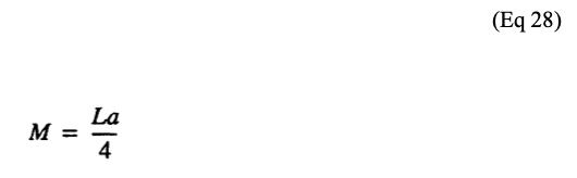
(M) is the mutual inductance of choke coils (L1/L2) since Transformer Magnetic Field (Rp) is the excitation External Magnetic Field (Rp1/Rp2) by way of Unipolar Pulsing Core (53).

Electron Bounce Phenomenon 4×
-
Coupling Inductance (Rp) between the Primary coil (26) and Secondary Coil (52) is further extrapolated in the following equation: Where, (Lt) is the total inductance, (L1) and L2) are the inductance of each individual transformer coils (26)(52), (M) is the mutual inductance of each transformer coil (26/52) being in parallel relationship with fields aiding.
-
Coupling Inductance (Rp1) and (Rp2) in (690) of Figure (7-8) is further expressed in the following equation: Where, (Lt cc) is the total inductance of Choke Coils (FL1 - FL2), (L1) and (L2) are the inductance of each individual choke coil (56)(62) in series with Secondary Coil (52) Electrical Voltage Potential (700) of Figure (7-9) and being exposed to the same Voltage Transfor …
-
choke coils (L1/L2)
… Electrical Voltage Potential (700) of Figure (7-9) and being exposed to the same Voltage Transformer (26 - 53 - 52) magnetic field (Rp) with aiding fields, (M) is the mutual inductance of choke coils (L1/L2) since Transformer Magnetic Field (Rp) is the excitation External Magnetic Field (Rp1/Rp2) by way of Unipolar Pulsing Core (53).
-
… electrical Voltage potential 66 since the Voltage Coefficient of Inductance (FL1/FL2), Voltage Coefficient of Capacitance (Cd1/Cd2), and Voltage Coefficient of Resistance (Rs1/Rs2) across choke coils (L1/L2) are the same values