(FL) · also written as a run, FLa xxx FLn
Optimize The Electromagnetic Field Strength
Also written Inductance Field Strength · Inductance Reactance · Impedance Field · Inductance · Impedance
Where it is first named
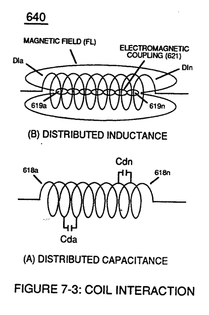
... outputting Voltage-wave signal (64a xxx 64n) being a pulse-frequency doubler due to Inductance Reactance (FL) of Inductor Coil (56) of Figure (3-22) when collapsing magnetic field (FL) of Figure (7-3b) re-cuts coil-wrap (Ll) during each pulse off-time (T2)
How it is written
- (FL) 6×
- (FLa xxx FLn) 1×
FLa xxx FLn is Meyer's shorthand for a run of the same thing: FLa is the first, FLn the last, and the x's stand for however many lie between. Every stage of the run is this one numeral.
Drawings 54
-
(FI) of Figure (7-3b) · Instant Explosion of Water
-
Figure (7-3) · Inductance (FL)
-
(640) of Figure (7-3) · Capacitance (Cd)
-
Figure (7-3) · Multi-layer Coil
-
Carries this number · WFC 426 - Illustrations
-
self-inductance (640) of Figure 7-3B) · Propagating Electrical Stress
-
"bifilar" wrapped coils (Figure 7-3) · Propagating Electrical Stress
-
Carries this number · VIC Switchover Circuit
-
Figure (3-22) · Analog Voltage generator (40)
-
Figure (3-22) · Voltage Amplitude Control Circuit (50)
-
Figure (3-22) · Voltage Intensifier Circuit (60)
-
Figure (3-22) · Voltage Dynamics
-
Voltage Intensifier Circuit (60) of Figure (3-22) · Gas Processor
-
The figure it sits on · WFC 422DA - Illustrations
-
The figure it sits on · VIC Matrix Circuit
-
Voltage Intensifier Circuit (60) of Figure (3-22) · Instant Explosion of Water
-
(56/62) of Figure (3-22) · Instant Explosion of Water
-
(700) of Figure (7-9) · Instant Explosion of Water
-
(T2) of Figure (7-8) · Instant Explosion of Water
-
(56) of Figure (3-22) · Instant Explosion of Water
-
Figure (7-8) · Resistance (Rs)
-
(690) of Figure (7-8) · Resistance (Rs)
-
(710) of Figure (7-10) · Inductance (FL)
-
(670) of Figure (7-6) · Inductance (FL)
-
(690) of Figure (7-8) · Inductance (FL)
-
(670) of Figure (7-6) · Capacitance (Cd)
-
(710) of Figure (7-10) · Capacitance (Cd)
-
(670) of Figure (7-6) · Capacitance (Cd)
-
(690) of Figure (7-8) · Capacitance (Cd)
-
(690) of Figure (7-8) · Inductance Reactance (Rs - Cd - FL)
-
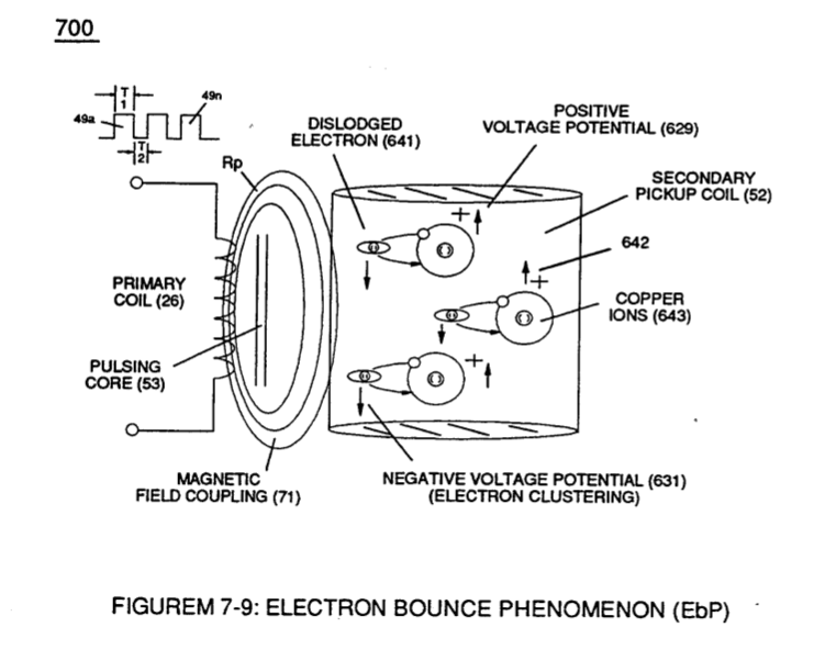
"Electron Bounce" phenomenon (700) of Figure (7-9) · Inductance Reactance (Rs - Cd - FL)
-
Figure (7-8) · Inductance Reactance (Rs - Cd - FL)
-
The figure it sits on · Taper Resonant Capacitor (ERt)
-
(690) of Figure (7-8) · Taper Resonant Capacitor (ERt)
-
Resonant Capacitor (140 -170) of Figure (7-6) · Capacitance Reactance
-
690 of Figure 7-8 · Circuit Resistance
-
... each bobbin cavity adhering to equation (Eq 20), as illustrated in (710) of Figure (7-10). · Transformer Action
-
(710) of Figure (7-10) · Transformer Action
-
Resonant Voltage Effect (670) of Figure (7-6) · Transformer Action
-
"Electron Clustering" (Grouping/collecting negative charged particles at a given point) (700) of Figure (7-9) · Transformer Action
-
(52) of Figure (7-8) · Electron Bounce Phenomenon
-
(700) of Figure (7-9) · Electron Bounce Phenomenon
-
The figure it sits on · WFC 426 - Illustrations
-
The figure it sits on · WFC 426 - Illustrations
-
(690) of Figure (7-8) · 8-2 - Traveling Voltage Wave-Guides
-
(631) of Figure (7-9) · 8-3 - Electrical Voltage-Pulse Wave-Transmission
-
(52) of Figure (7-8) · 8-3 - Electrical Voltage-Pulse Wave-Transmission
-
(Cp) of Figure (7-8) · 8-4 - State Space (Sp)
-
(690) of Figure (7-8) · 8-6 - VIC Voltage Sync-Pulse Circuit
-
(Cp) of (7-8) · 8-6 - VIC Voltage Sync-Pulse Circuit
-
(690) of Figure (7-8) · Propagating Electrical Stress
-
Voltage Intensifier Circuit (60) of Figure (3-22) · Propagating Electrical Stress
-
(60) of Figure (3-22) · Propagating Electrical Stress
-
The figure it sits on · WFC 429 - Illustrations
Where it is named · 7
Instant Explosion of Water 2×
-
Inductance Reactance (FL)
... outputting Voltage-wave signal (64a xxx 64n) being a pulse-frequency doubler due to Inductance Reactance (FL) of Inductor Coil (56) of Figure (3-22) when collapsing magnetic field (FL) of Figure (7-3b) re-cuts coil-wrap (Ll) during each pulse off-time (T2)
-
... outputting Voltage-wave signal (64a xxx 64n) being a pulse-frequency doubler due to Inductance Reactance (FL) of Inductor Coil (56) of Figure (3-22) when collapsing magnetic field (FL) of Figure (7-3b) re-cuts coil-wrap (Ll) during each pulse off-time (T2)
Inductance Reactance (Rs - Cd - FL) 3×
-
Inductance (FL)
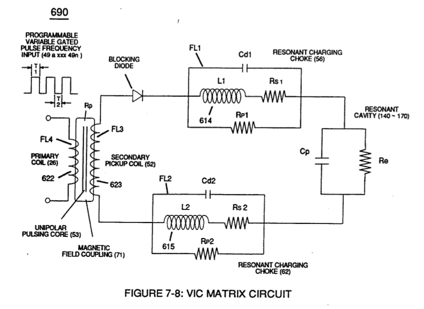
Inductance Reactance occurs when resistance (Rs), capacitance (Cd), and Inductance (FL) interacts together during D.C. Pulsing (49a xxx 49n), as schematically depicted in (690) of Figure (7-8).
-
Impedance Field (FL)
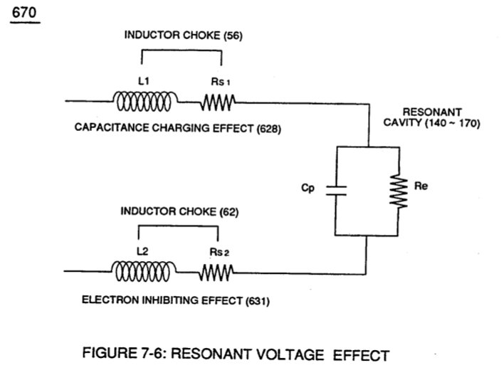
Inductance Reactance not only increases voltage across water-capacitor (ER) beyond applied Voltage Potential (626) of Figure (7-7) but, also, establishes "Impedance Field" (FL) across Inductors (L1-L2) of Figure (7-6) which acts and performs as Resonant Charging Chokes (614/615) of Figure (7-1) once placed on opposite side of capacitor (ER) forming Resonant voltage Effect C …
-
optimize the electromagnetic field strength (FL)
Both Inductors (LI/L2) are Bifilar wound in equal length to optimize the electromagnetic field strength (FL) in equal electromagnetic intensity (FL1 = FL2) to encourage and promote "Electron Bounce" phenomenon (700) of Figure (7-9) while adjusting (programmable pulse wave-form) input signal Pulse-Frequency …
In-Line Circuit Components 1×
-
Impedance (FL)
... determining voltage swing from highest voltage level (Vn) to volts switch-off point (Vff), and establishing Impedance (FL) which minimizes heat loss of electrical input power (49) by impairing electron movement.
Multi-layer Coil 1×
-
Inductance Field Strength (FLa xxx FLn)
… section can be computed by below formula when optimizing maximum distributed capacitance (Cda xxx Coo) and distributed inductance (Dla xxx Dln) of Figure (7-3) to intensify Inductance Field Strength (FLa xxx FLn) to function as a voltage multiplier in switch-off conditions (612a xxx 612n), as illustrated in (710) of ~ . Figure (7-10) as to VIC Coil Assembly (580) of Figure (6-1) and, is expressed: