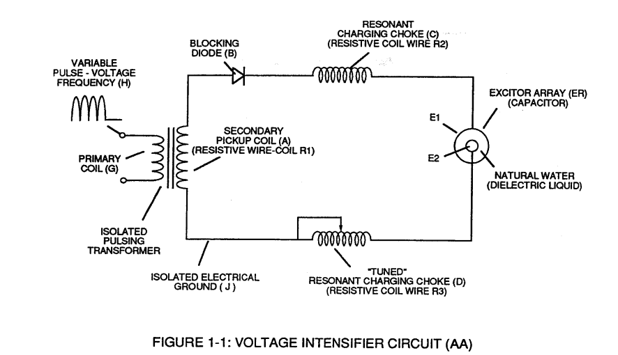
Figure (1-1)
Voltage Intensifier Circuit
Also written WFC Water Fuel Injection System
How it is written
- (1-1) 20×
Drawings 7
-
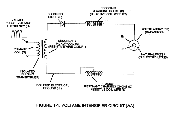
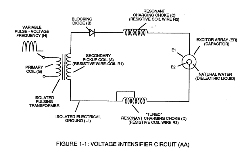
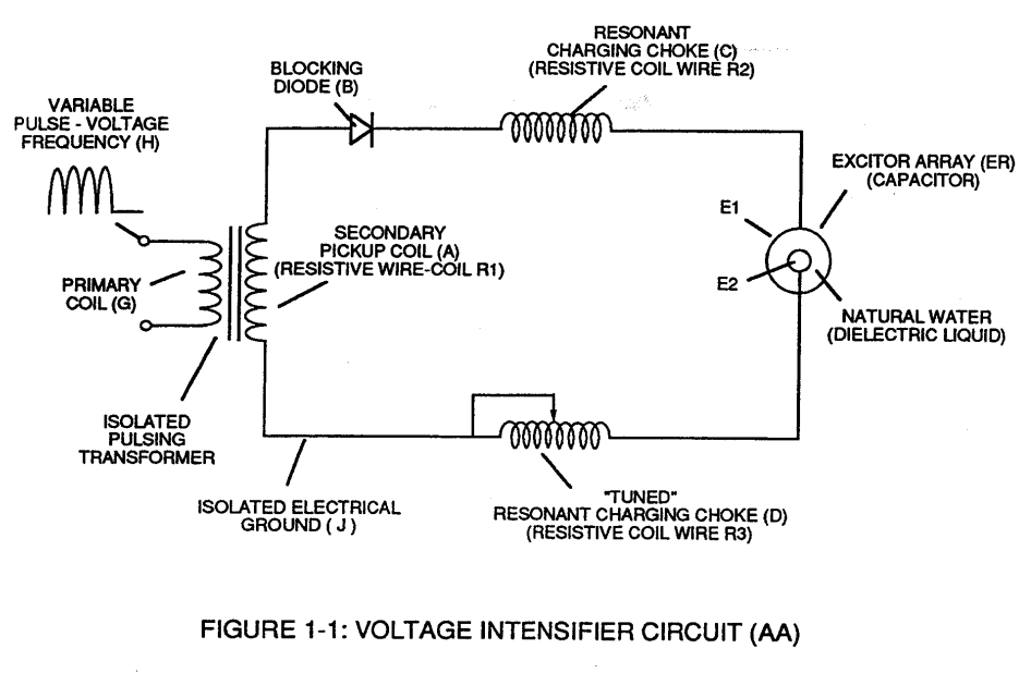
Figure 1-1 · RLC CIRCUIT
-
The primary coil is electrically isolated (no electrical connection between primary and secondary coil) to form Voltage Intensifier Circuit (AA) Figure (1-1). · Pulsing Transformer
-
Captioned as this figure · Electronic Circuit Design
-
Water Fuel Injection System (10) of Figure (1) · Water Fuel Injector (Taper Resonant Cavity Chamber)
-
Figure (1-1) (Memo WFC 420) · Instant Explosion of Water
-
(E1/E2) of Figure (1-1) page (1-13) · Taper Resonant Capacitor (ERt)
-
Figure (1-1) · Propagating Electrical Stress
On this figure 5
Where it is named · 20
WFC 417 — WFC 417 2×
-
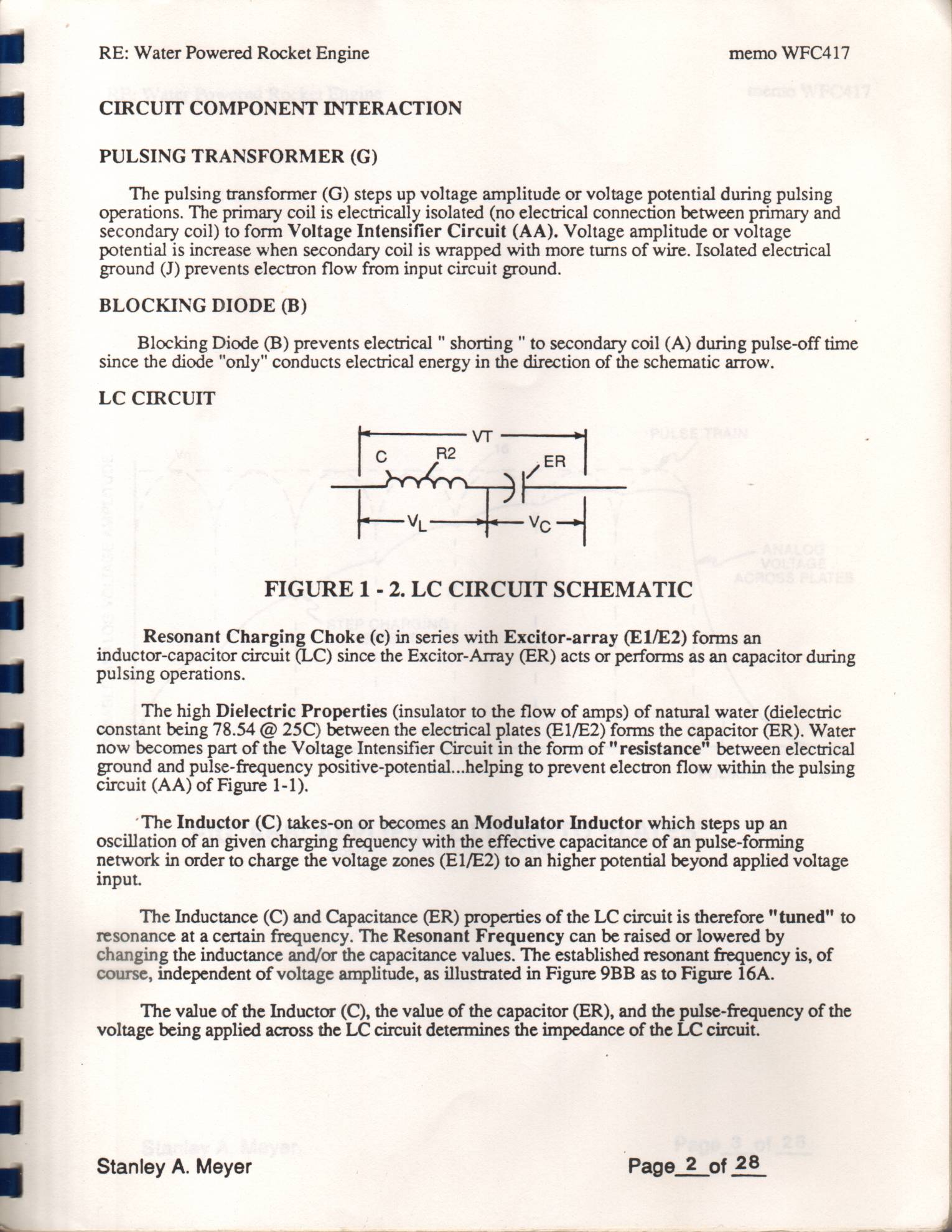
The high Dielectric Properties (insulator to the flow of amps) of natural water (dielectric constant being 78.54 @ 25C) between the electrical plates (E1/E2) forms the capacitor (ER). Water now becomes part of the Voltage Intensifier Circuit in the form of "resistance" between electrical ground and pulse-frequency positive-potential...helping to prevent electron flow within the pulsing circuit (AA) of Figure 1-1).
-
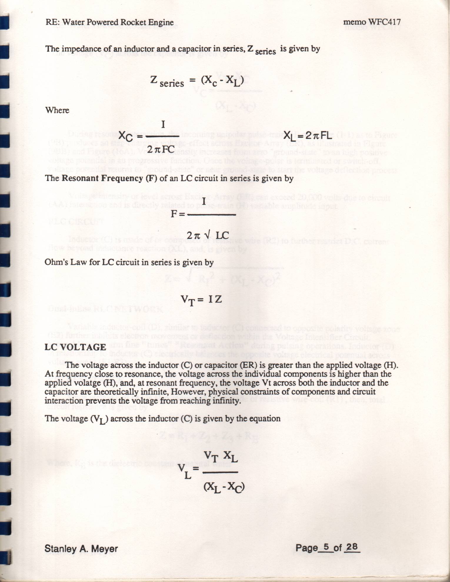
During resonant interaction, the incoming unipolar pulse-train (H) of Figure (1-1) as to Figure
CIRCUIT COMPONENT INTERACTION 1×
-
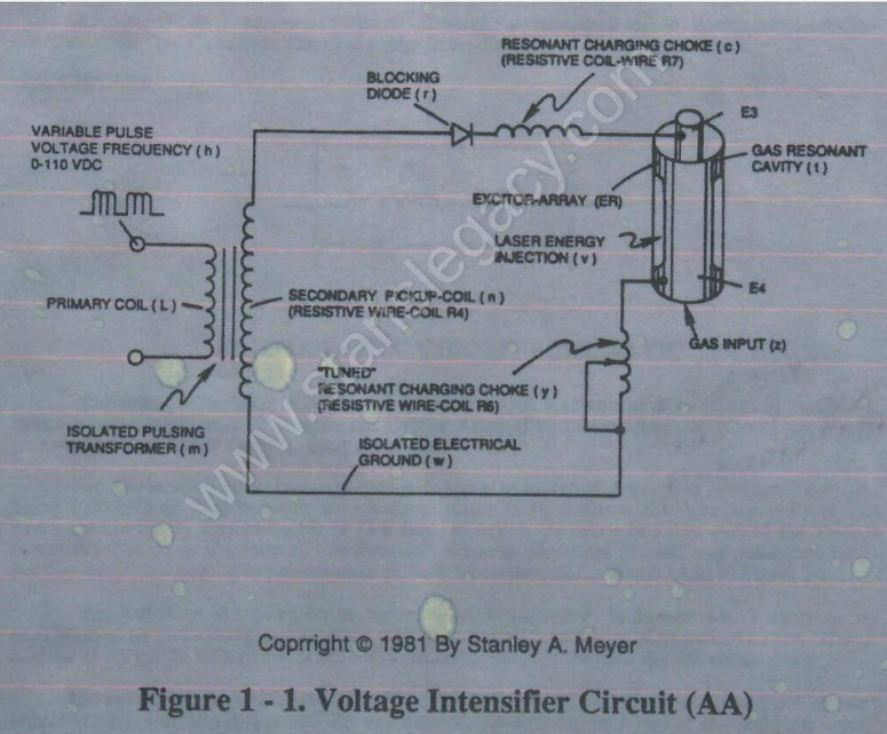
Gas Molecule or Gas atom of Argon (Ar) now becomes part of the Voltage Intensifier Circuit in the form of “resistance” between electrical ground and pulse-frequency positive-potential... helping to prevent electron flow within the pulsing circuit (AA) of Figure 1-1.
RLC CIRCUIT 2×
-
During resonant interaction, the incoming unipolar pulse-train (h) of Figure (1-1) as to Figure (9B) produces an step-charging voltage-effect across Excitor-Array (ER of t), as illustrated in Figure progressive function.
-
Figure 1-1
LASER INTERACTION 1×
-
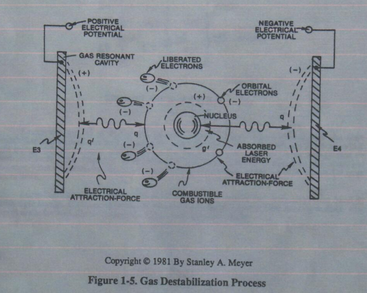
Laser energy (v) of Figure 1-1 is now injected into or superimposed onto the Gas Destabilization Process to help promote the Electron Extraction Process since the absorbed light energy (electromagnetic energy) forces the gas atom electrons to an higher energy state or attraction-force (q2) between the orbital electrons and the nucleus…
Pulsing Transformer 1×
-
The primary coil is electrically isolated (no electrical connection between primary and secondary coil) to form Voltage Intensifier Circuit (AA) Figure (1-1).
LC Circuit 3×
-
Figure (1-1)
-
... helping to prevent electron flow within the pulsing circuit (AA) of Figure 1-1.
LC Voltage 2×
-
Figure (1-1)
Atomic Interaction to Voltage Stimulation 2×
-
Voltage potential within an electrical circuit (see Voltage Intensifier Circuit as to Figure 1-1) can cause one or more electrons to be dislodged from the atom due to opposite polarity attraction between unlike charged entities, as shown in Figure (1-8).
-
Voltage Intensifier Circuit as to Figure 1-1
Instant Explosion of Water 2×
-
Voltage Intensifier Circuit (60) of Figure (3-22) (Memo WFC 422 DA) as to Figure (1-1) (Memo WFC 420) and Voltage Intensifier Circuit (620) of Figure (7-1) are specifically designed to restrict amp flow during Programmable Pulsing Operations (49a xxx 49n) but in different operational modes:
-
Figure (1-1) (Memo WFC 420)
Taper Resonant Capacitor (ERt) 2×
Propagating Electrical Stress 2×
-
Figure (1-1)