(35) · also written as a run, 35a xxx 35n
Resonant Cavity Zone
Also written Resonant Cavity · voltage level · Linear Voltage Surfaces · Voltage Surfaces · Voltage Compressional Wave-form · Expanding Voltage Waveform · fuel-mixing chamber · voltage point and 3 more
Where it is first named
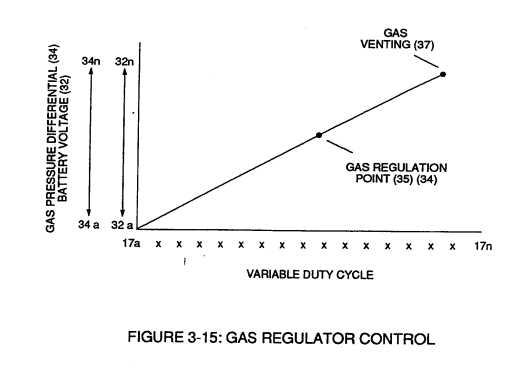
Regulator stage (27) of circuit (50) converts battery voltage potential (29) of Figure (3-6) via electrical terminal (31) of Figure (3-5) as to Figure (3-6) into a analog voltage signal (32) of Figure (3-15) which corresponds to but is electrically isolated (crossover voltage from two separate power supplies) from incoming gas volume signal (23) of Figure (3-14), as shown in Figure (35).
How it is written
- (35) 18×
- (35a) 2×
- (35b) 2×
- (35c) 2×
- (35a/35b/35c) 1×
- (35b/35c) 1×
35a xxx 35n is Meyer's shorthand for a run of the same thing: 35a is the first, 35n the last, and the x's stand for however many lie between. Every stage of the run is this one numeral.
Drawings 64
-
Figure (3-15) · Voltage Amplitude Control Circuit (50)
-
In terms of assembly, gas resonant cavity (410), electron extraction circuit (270), optical lens (121) forms gas processor (260) of Figure (3-31). · Gas Processor
-
Carries this number · WFC 422DA - Illustrations
-
Carries this number · WFC 422DA - Illustrations
-
Carries this number · WFC 422DA - Illustrations
-
Carries this number · Water Fuel Injection System
-
Carries this number · Differential Air-Gas Inlet Control
-
(70) of Figure (3B) · Water Fuel Injector (Taper Resonant Cavity Chamber)
-
Carries this number · Water Fuel Injector (Taper Resonant Cavity Chamber)
-
(280) of Figure (34) · Funneling Effect
-
Figure (4-5) · Water Fuel Injection System - Page 1
-
but, also prevents electron flow into destabilizing gas process (180), as so illustrated in Figure (4-5). · Water Fuel Injection System - Page 3
-
Carries this number · In Application of Usage
-
(57) of Figure (6-2) · In Application of Usage
-
Voltage Triggering Process (70) of Figure (4-5) · Voltage Intensifier Coil-Assembly
-
(16) of Figure (4-5) · Resistance (Rs)
-
(720) of Figure (7-11) · Capacitance (Cd)
-
(590) of Figure (6-2) · Capacitance (Cd)
-
(730) of Figure (7-12) · Taper Resonant Capacitor (ERt)
-
diagram 720 of Figure 7-11 · Taper Resonant Capacitor (ERt)
-
Figure (4-5) · Capacitance Reactance
-
Traveling Electrical Voltage Wave-forms (730a - b - c) of Figure (7-12) · Electron Bounce Phenomenon
-
(E9/10) of Figure (6-2) · Voltage Amplitude Switch-Off
-
Compressional Wave-form (B) of Figure (7-12) · Voltage Amplitude Switch-Off
-
Carries this number · Mode of Operability
-
Carries this number · WFC 426 - Illustrations
-
Carries this number · WFC 426 - Illustrations
-
(730A) of Figure (7-12) · 8-2 - Traveling Voltage Wave-Guides
-
(570) of Figure (7-12) · 8-2 - Traveling Voltage Wave-Guides
-
(720) of Figure (7-11) · 8-2 - Traveling Voltage Wave-Guides
-
Figure (4-5) · 8-5 - Energy Vectoring (Ev)
-
(730) of Figure (7-12) · 8-5 - Energy Vectoring (Ev)
-
(730C) of Figure (7-12) · 8-7 - Application of Usage
-
(730A) of Figure (7-12) · 8-7 - Application of Usage
-
(280) of Figure (3-35) · Voltage to Amp Differential Ratio
-
The figure it sits on · Laser Accelerator Assembly
-
The figure it sits on · Analog Voltage generator (40)
-
Figure (3-1) · Voltage Amplitude Control Circuit (50)
-
Figure (3-24) · Voltage Amplitude Control Circuit (50)
-
Figure (3-24) · Electrical Polarization process
-
To further prevent voltage fluctuation during resonant action, Phase Lock Loop technique of Pulse Indicator circuit (110) is utilized during pulsing operations. · Resonant Action
-
Figure (3-1) · Laser Distributor
-
Hydrogen Fuel-Gas Assembly (450) of Figure (3-1) · Operational Parameters
-
Fuel Cell (120) of Figure (3-24) · Operational Parameters
-
The figure it sits on · WFC 422DA - Illustrations
-
The figure it sits on · WFC 422DA - Illustrations
-
The figure it sits on · WFC 422DA - Illustrations
-
3-14 WFC Voltage Ignition Wire · Voltage Intensifier Coil Assembly
-
The figure it sits on · Electronic Circuit Design
-
Voltage Intensifier Circuit (620) of Figure (7-1) · Instant Explosion of Water
-
(620) of Figure (7-1) · Instant Explosion of Water
-
(620) of Figure (7-1) · Resistance (Rs)
-
(614) of Figure (7-1) · Inductance (FL)
-
Inductor (614) of Figure (7-1) · Inductance (FL)
-
(614) of (7-1) · Inductance (FL)
-
Figure (3-24) · Inductance (FL)
-
Figure (7-1) · Capacitance (Cd)
-
(620) of Figure (7-1) · Inductance Reactance (Rs - Cd - FL)
-
Choke-Coil (62) of Figure (7-1) · Transformer Action
-
The figure it sits on · WFC 426 - Illustrations
-
(620) of Figure (7-1) · 8-6 - VIC Voltage Sync-Pulse Circuit
-
The figure it sits on · WFC 427 Illustrations
-
"Resonant Charging Choke" (56) of Figure (7-1) · Propagating Electrical Stress
-
(620) of figure (7-1) · Voltage to Amp Differential Ratio
Where it is named · 26
Voltage Amplitude Control Circuit (50) 6×
-
Regulator stage (27) of circuit (50) converts battery voltage potential (29) of Figure (3-6) via electrical terminal (31) of Figure (3-5) as to Figure (3-6) into a analog voltage signal (32) of Figure (3-15) which corresponds to but is electrically isolated (crossover voltage from two separate power supplies) from incoming gas volume signal (23) of Figure (3-14), as shown in Figure (35).
-
voltage level (35)
If for example, Fuel Gas production is greater than demand, then, analog signal (32) is reduced to proper voltage level (35) (voltage level directly determines gas pressure via Resonant Action) required to maintain gas pressure (34).
-
voltage level (35)
Conversely, analog signal (32) is always allowed to exceed voltage level (35) during injection (36) of Figure (3-1) until gas-point (34) is reached.
-
gas-point (35)
In cases where linear voltage (32) drops (descending value) below gas-point (35) then gas regulator stage (28) increases voltage amplitude (32a xxx 32n) (analog voltage) to voltage point (35).
-
voltage point (35)
In cases where linear voltage (32) drops (descending value) below gas-point (35) then gas regulator stage (28) increases voltage amplitude (32a xxx 32n) (analog voltage) to voltage point (35).
-
gas point (35)
If gas pressure (34a xx) should exceed gas point (35) during injector off-time, gas pressure release valve (75) of Figure (3-24) (gas venting 37 of Figure 3-15) expels Fuel gases (88) until gas point (34) is either reached or a delay timing circuit acti …
Water Fuel Injection System 1×
-
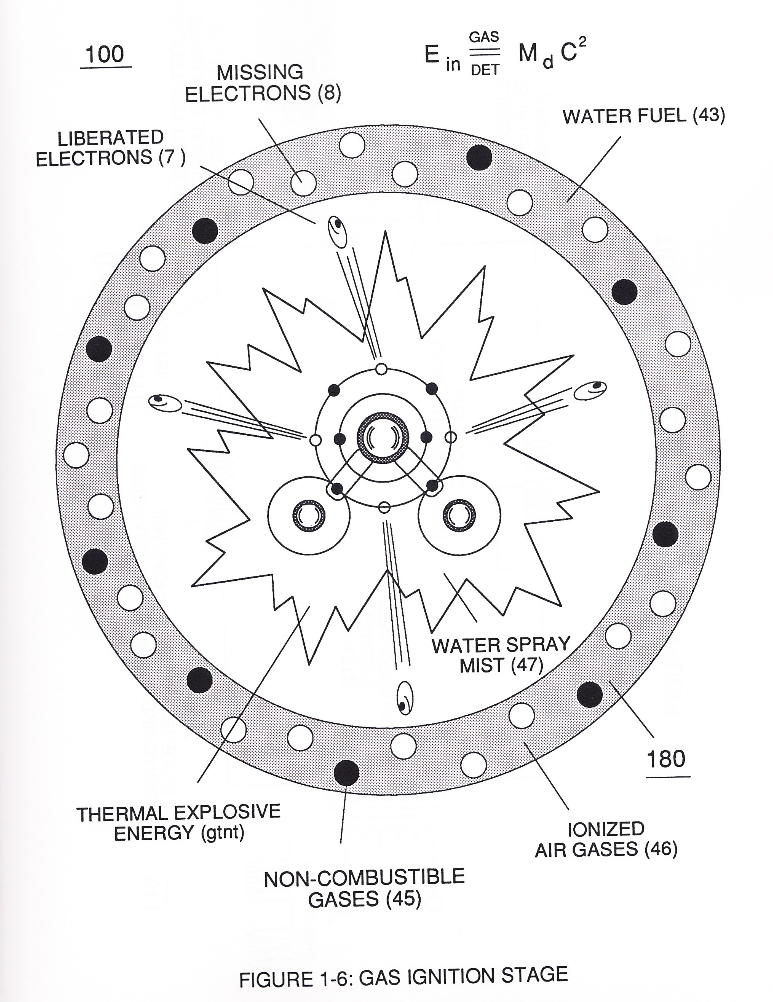
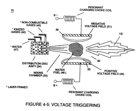
First water mist (47) of Figure (1-3A) is injected into fuel-mixing chamber (35) of Figure (3B) by way of water spray ports (41a xxx 41n) of Figure (3A);
Water Fuel Injector (Taper Resonant Cavity Chamber) 2×
-
Once water fuel-droplets (xxx 48n) fully occupies open space cavity (Resonant Cavity Zone) (35) and then exposed to applied pulsating opposite electrical voltage fields (49/51) of voltage wave form (280) of Figure (17), the electrically stimulated water fuel droplets (48a xxx 48n) are subjected to release thermal explosive energy (gtnt) (16) undergoing Electrical-Resonant in a sequential manner:
-
Resonant Cavity Zone (35)
... forming a capacitor (E7 / E8) in series with Resonant Charging Chokes (56/57) placed on opposite sides of Resonant Cavity Zone (35) as to Figure (7) and (8) . . . forming a Resonant Pulsing Circuit (110) of Figure (7) with step-up Pulsing Transformer (33/36), as shown in (220) of Figure (18).
Funneling Effect 6×
-
Resonant Cavity Zone (35)
Enhancement of the operational parameters of Hydrogen Fracturing Process (100) of Figure (6) is further exemplified when incoming Resonant voltage-wave (58) of Figure (18) electrically transmitted across Resonant Cavity Zone (35) during water injection cycle...
-
Resonant Cavity Zone (35)
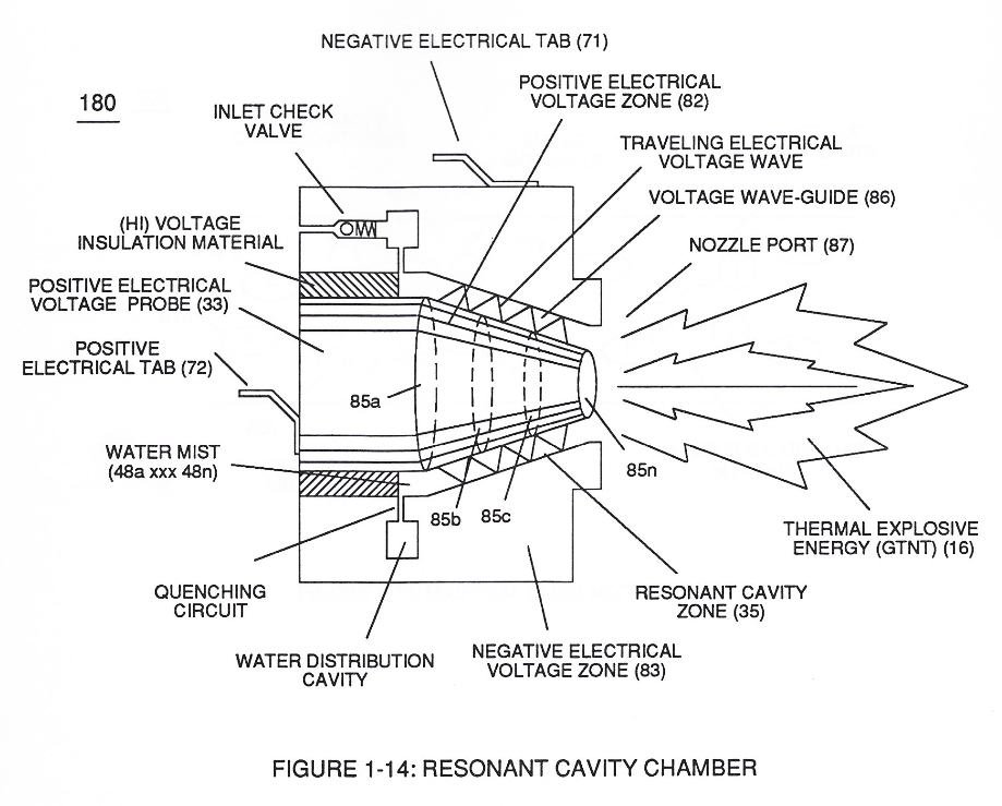
causing Resonant Cavity Zone (35) to function and perform as a voltage wave-guide (86) of Figure (14) since the gradual decrease in cross-sectional circumference area (85) of Figure (14) is in linear progression ... reducing both voltage surfaces areas (83/84) in parallel space relationship from larger segmental area (85a) to smaller segmental area (85n).
-
Resonant Cavity Zone (35)
This resultant "Funneling Effect" (260), now, allows voltage amplitude (Vn) wave-form (58) to travel the length of Resonant Cavity Zone (35) from Start-Point (85a) to End-Point (85n) increasing voltage intensity (xxx VL = Vn) as parallel voltage surfaces (83/84) diminishes in size relationship (85a ~ 85n), as illustrated in (210) of Figure (17).
-
Resonant Cavity (35)
To prevent pre-ignition of gases traveling toward Exit-Port (87), Resonant Cavity (35) open space (open resonant cavity) parallel dimension between positive voltage surface (82) and negative voltage surface (83) is small enough (typically .010 or so) to function as a Quenching Circuit, as illustrated in Figure (24SD) (missing image) (WFC Memo 420).
-
Resonant Cavity Zone (35)
This resultant "Shunting Effect", now, allows voltage intensity (Vma = Vmn) to be placed across Resonant Cavity Zone (35) to not only compensate for water impurity that might alter the operational parameters of Hydrogen Fracturing Process (100) as to (390) but, also, provide "Instant" "Power-Boost" when needed.
-
Resonant Cavity (35)
This newly formed synchronized and repetitive dual expanding voltage wave form (77a xxx 77n) is further enhanced by "Funneling Effect" (260)... maximizing voltage dynamic across Resonant Cavity (35) always subjecting and exerting increase "Electrical-Stress" (SS'-RR' / TT'-UU') of opposite polarity across Hydrogen Fracturing Process (100 / 390) to the point of gas ignition.
Water Fuel Injection System - Page 1 1×
-
fuel-mixing chamber (35)
First water mist (47) of Figure (4-4) is injected into fuel-mixing chamber (35) of Figure (4-5) by way of water spray ports (41a xxx 41n) of Figure (4-4);
Taper Resonant Capacitor (ERt) 4×
-
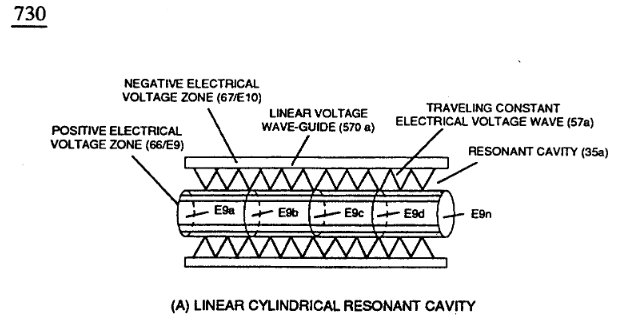
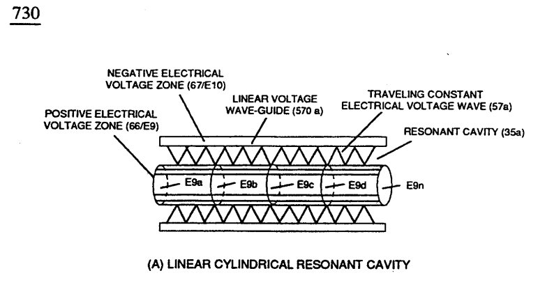
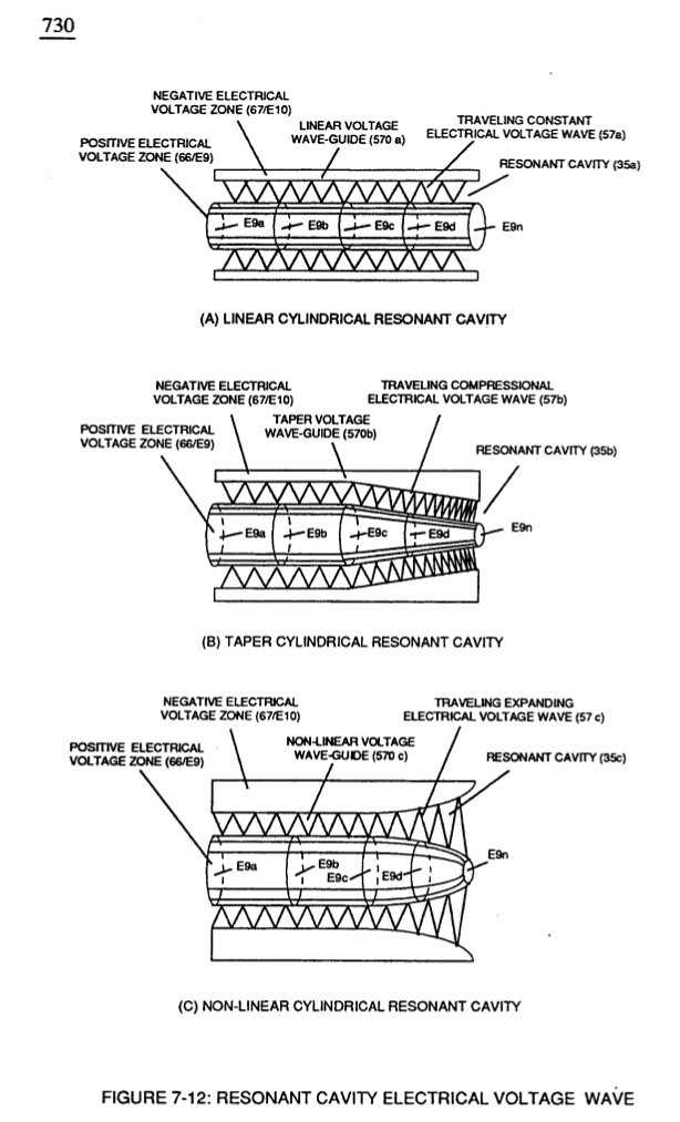
(35a) Traveling Constant Electrical Voltage Wave by way of linear cylindrical resonant cavity (Tubular Cavity 730A),
-
(35b) Traveling Compressional (concentrating electrical intensity) Electrical Voltage Wave by way of taper cylindrical resonant cavity (730B),
-
(35c) Traveling Expanding Electrical Voltage wave by way of non-linear cylindrical resonant cavity (730C)
-
... each resonant cavity design acting and functioning as a Voltage Wave-guide (570) and gap-size (35) sufficient enough to allow the "Quenching Effect" to take place, as illustrated in (730) of Figure (7-12) as to (370) of Figure (3-40).
Mode of Operability 5×
-
Voltage Compressional Wave-form (35b)
Voltage Compressional Wave-form (35b) and Expanding Voltage Waveform (35c) increases the intensity of applied pulsating opposite electrical attraction force (55'-RR'a xxx SS'-RR'n) even further during each new pulse-cycle (T2 next T2) across water gap (616)
-
Expanding Voltage Waveform (35c)
Voltage Compressional Wave-form (35b) and Expanding Voltage Waveform (35c) increases the intensity of applied pulsating opposite electrical attraction force (55'-RR'a xxx SS'-RR'n) even further during each new pulse-cycle (T2 next T2) across water gap (616)
-
Voltage Surfaces (35b/35c)
... increasing Thermal Explosive Energy-yield (gtnt) to higher energy-levels (gtnta xxx gtntn) beyond applied excitation voltage (Vn) by simply altering Voltage Surfaces (35b/35c) as in reference to Linear Voltage Surfaces (35a), as illustrated in (730) of Figure (7-12).
-
Linear Voltage Surfaces (35a)
... increasing Thermal Explosive Energy-yield (gtnt) to higher energy-levels (gtnta xxx gtntn) beyond applied excitation voltage (Vn) by simply altering Voltage Surfaces (35b/35c) as in reference to Linear Voltage Surfaces (35a), as illustrated in (730) of Figure (7-12).
-
Wave-guides (35a/35b/35c)
Pulse Off-time (T2) of Figure (7-8) as to (620) of Figure (7-1) is adjusted to compensate for the rise and fall of magnetic coupling field (71) to produce applied Unipolar Wave-forms (64a xxx 64n) entering into Wave-guides (35a/35b/35c).
8-2 - Traveling Voltage Wave-Guides 1×
-
… age surface (66/E9) and negative electrical voltage surface (67/E10) are placed in parallel space relationship to form voltage surfaces (E9/E10) about an cylindrical axis of rotation having space-gap (35) there between and thus, fanning Cylindrical Resonant Cavity (730A) of Figure (7-12) as to (770A) of Figure (8-1) when space-gap (616) of Figure (720) exposes injected water bath (85) to unipolar puls …